1
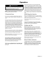
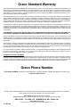
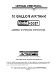
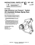
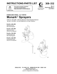
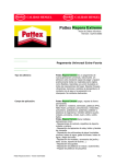
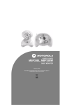
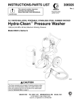
INSTRUCTIONS-PARTS LIST
This manual contains important
warnings and information.
READ AND KEEP FOR REFERENCE.
307–636
Rev. J
Supersedes Rev. G
First choice when
and PCN H
quality counts.
INSTRUCTIONS
AIR-ASSISTED AIRLESS
10:1 Ratio Monark Sprayers
950 psi (6.6 MPa, 66 bar) Maximum Fluid Working Pressure
95 psi (0.66 MPa, 6.6 bar) Maximum Air Working Pressure
Model 230–998, Series B
Includes pump and 5 gallon (19 liter) pail
Model 231–015
Includes pump 230–998, hose, gun, and tip
Model 230–978 Series B
Includes pump 230–998, fluid regulation kit 222–564,
hose, gun, and tip
MODEL 230–978
(GUN AND HOSES
NOT SHOWN)
GRACO INC.
P.O. BOX 1441 MINNEAPOLIS, MN
Graco Inc. is registered to I.S. EN ISO 9001
55440–1441
Table of Contents
Warnings . . . . . . . . . . . . . . . . . . . . . . . . . . . . . . . . . . . . . . 2
Installation . . . . . . . . . . . . . . . . . . . . . . . . . . . . . . . . . . . . 6
Operation . . . . . . . . . . . . . . . . . . . . . . . . . . . . . . . . . . . . 10
Parts . . . . . . . . . . . . . . . . . . . . . . . . . . . . . . . . . . . . . . . . 12
Technical Data . . . . . . . . . . . . . . . . . . . . . . . . . . . . . . . . 14
Warranty . . . . . . . . . . . . . . . . . . . . . . . . . . . . . . . . . . . . . 16
Graco Phone Number . . . . . . . . . . . . . . . . . . . . . . . . . . 16
Symbols
Warning Symbol
WARNING
This symbol alerts you to the possibility of serious
injury or death if you do not follow the instructions.
Caution Symbol
CAUTION
This symbol alerts you to the possibility of damage to
or destruction of equipment if you do not follow the
corresponding instructions.
WARNING
EQUIPMENT MISUSE HAZARD
Equipment misuse can cause the equipment to rupture or malfunction and result in serious injury.
INSTRUCTIONS
D This equipment is for professional use only.
D Read all instruction manuals, tags, and labels before operating the equipment.
D Use the equipment only for its intended purpose. If you are uncertain about usage, call your Graco
distributor.
D Do not alter or modify this equipment. Use only genuine Graco parts and accessories.
D Check equipment daily. Repair or replace worn or damaged parts immediately.
D Do not exceed the maximum working pressure of the lowest rated system component. Refer to the
Technical Data on page 14 for the maximum working pressure of this equipment.
D Use fluids and solvents which are compatible with the equipment wetted parts. Refer to the Technical Data section of all equipment manuals. Read the fluid and solvent manufacturer’s warnings.
D Do not exceed the maximum working pressure of the lowest rated system component. This equipment has a 950 psi (6.6 MPa, 66 bar) maximum working pressure.
D Do not use hoses to pull equipment.
D Route hoses away from traffic areas, sharp edges, moving parts, and hot surfaces. Do not expose
Graco hoses to temperatures above 82_C (180_F) or below –40_C (–40_F).
D Wear hearing protection when operating this equipment.
D Do not lift pressurized equipment.
D Comply with all applicable local, state, and national fire, electrical, and safety regulations.
307–636
WARNING
INJECTION HAZARD
Spray from the gun, hose leaks, or ruptured components can inject fluid into your body and cause
extremely serious injury, including the need for amputation. Fluid splashed in the eyes or on the skin
can also cause serious injury.
Fluid injected into the skin might look like just a cut, but it is a serious injury. Get immediate medical attention.
Do not point the gun at anyone or at any part of the body.
Do not put your hand or fingers over the spray tip.
Do not stop or deflect leaks with your hand, body, glove or rag.
Do not “blow back” fluid; this is not an air spray system.
Always have the tip guard and the trigger guard on the gun when spraying.
Check the gun diffuser operation weekly. Refer to the gun manual.
Be sure the gun trigger safety operates before spraying.
Lock the gun trigger safety when you stop spraying.
Follow the Pressure Relief Procedure on page 10 whenever you: are instructed to relieve pressure; stop spraying; clean, check, or service the equipment; and install or clean the spray tip.
Tighten all fluid connections before operating the equipment.
Check the hoses, tubes, and couplings daily. Replace worn, damaged, or loose parts immediately.
Permanently coupled hoses cannot be repaired; replace the entire hose.
Use only Graco approved hoses. Do not remove any spring guard that is used to help protect the
hose from rupture caused by kinks or bends near the couplings.
307–636
3
WARNING
FIRE AND EXPLOSION HAZARD
Improper grounding, poor ventilation, open flames or sparks can cause a hazardous condition and
result in a fire or explosion and serious injury.
Ground the equipment and the object being sprayed. Refer to Grounding on page 6.
If there is any static sparking or you feel an electric shock while using this equipment, stop spraying immediately. Do not use the equipment until you identify and correct the problem.
Provide fresh air ventilation to avoid the buildup of flammable fumes from solvents or the fluid
being sprayed.
Keep the spray area free of debris, including solvent, rags, and gasoline.
Electrically disconnect all equipment in the spray area.
Extinguish all open flames or pilot lights in the spray area.
Do not smoke in the spray area.
Do not turn on or off any light switch in the spray area while operating or if fumes are present.
Do not operate a gasoline engine in the spray area.
TOXIC FLUID HAZARD
Hazardous fluid or toxic fumes can cause serious injury or death if splashed in the eyes or on the skin,
inhaled, or swallowed.
Know the specific hazards of the fluid you are using.
Store hazardous fluid in an approved container. Dispose of hazardous fluid according to all local,
state and national guidelines.
Always wear protective eyewear, gloves, clothing and respirator as recommended by the fluid and
solvent manufacturer.
4
307–636
Notes
307–636
5
Installation
Grounding
To reduce the risk of static sparking, ground the pump,
object being sprayed, and all other spray/dispensing
equipment used or located in the spray/dispensing
area. Check you local electrical code for detailed
grounding instructions for your area and type of equipment. Be sure to ground all of this spray/dispensing
equipment:
1. Pump: loosen the grounding lug locknut (W) and
washer (X). Insert one end of a 1.5 mm2 (12 ga)
minimum ground wire (Y) into the slot in lug (Z)
and tighten the locknut securely. See Fig. 1.
Connect the other end of the wire to a true earth
ground. Order Part No. 237–569, Ground Wire and
Clamp.
5. Object being sprayed: according to your local
code.
6. Fluid supply container: according to your local
code.
7. All solvent pails used when flushing, according to
local code. Use only metal pails, which are conductive, placed on a grounded surface. Do not
place the pail on a nonconductive surface, such as
paper or cardboard, which interrupts the grounding
continuity.
8. To maintain grounding continuity when flushing or
relieving pressure, always hold a metal part of the
spray gun firmly to the side of a grounded metal
pail, then trigger the spray gun.
Z
Y
2. Air compressor: follow manufacturer’s recommendations.
3. Air and fluid hoses: use only grounded hoses with
a maximum of 500 ft (150 m) combined hose
length to ensure grounding continuity.
4. Spray gun: grounding is obtained through connection to a properly grounded fluid hose and pump.
6
307–636
W
Fig. 1
X
Installation
NOTES:
The reference numbers and letters in parentheses
in the text refer to the callouts in the drawings.
The accessories mentioned are available from your
Graco distributor.
The following manuals are supplied with your unit:
Manual Component
307–595
10:1 Ratio Monark Pump
308–640
Air–Assisted Airless
Spray Gun
308–167
Air Regulator
307–273
Fluid Filter
307–886
Fluid Regulator (Model 230–978
Sprayer only)
WARNING
For your safety in installing, operating, and servicing this system, thoroughly read and follow all
warnings and instructions given in this manual or in
any other manuals supplied with this system or any
accessories you add to the system. If a manual is
missing or you need additional copies, copies are
available from Graco at no charge.
All Models (See Fig 2)
DO NOT install the spray tip in the gun yet.
Install an air line filter (H) in the main air line, to remove harmful dirt and moisture from the compressed
air supply. Install a bleed–type master air valve (J)
close to the pump air inlet, and downstream from the
pump air regulator (K). Install a second bleed valve (L)
upstream from all other accessories, to isolate the
accessories for servicing.Connect an air supply hose
between the main air supply line and the sprayer’s air
inlet swivel (1).
CAUTION
To avoid contaminating the air supply to the gun, do
not use an automatic air line lubricator; lubricate the
motor manually, instead. See OPERATION on page
11.
WARNING
The bleed-type master air valve (J), air relief valve
(9), and fluid drain valve (E) are required in your
system, to help reduce the risk of serious injury
including fluid injection, splashing in the eyes or on
the skin, overpressurization, or injury from moving
parts if you are adjusting or repairing the pump.
The bleed-type master air valve relieves air trapped
between this valve and the pump. Trapped air can
cause the pump to cycle unexpectedly.
The air relief valve (supplied) opens automatically
to relieve air pressure to the pump if the pressure
exceeds a preset level. This valve prevents overpressurization of the spray gun.
The fluid drain valve assists in relieving fluid pressure in the displacement pump, hose, and gun;
triggering the gun to relieve pressure may not be
sufficient.
307–636
7
Installation
Assembling Sprayer Model 231–015
(See Fig 2)
Connect the gun air supply hose (71) between the air
inlet (A) of the gun (70) and the nipple (14) at the outlet
of the gun air regulator (B).
Connect the gun fluid supply hose (72) between the
gun fluid inlet (C) and the ball valve (D) mounted in the
side outlet of the fluid filter (25).
WARNING
To reduce the risk of serious injury, never connect a
fluid hose to the drain valve (E) mounted in the
bottom outlet of the fluid filter (25). This valve is for
use only as a drain valve, to relieve fluid pressure
in the system during shutdown.
Assembling Sprayer Model 230–978
(See Fig 2)
Remove the plug button (64) from the hole (F) in the
pail cover (40).
8
307–636
Assemble the fluid regulation kit (75) as shown in
Detail A and Detail B of Fig 2. Install the regulator
mounting bracket (75k) on the regulator (75f), using
the two screws (75p) and lockwashers (75q). Mount
the assembled regulator kit on the pail cover with the
capscrew (75l), washer (75m) and nut (75n). Connect
the regulator hose (75h) between the nipple (75b) at
the regulator inlet (G) and the ball valve (D) mounted
in the side outlet of the fluid filter (25).
Connect the gun air supply hose (71) between the air
inlet (A) of the gun and the nipple (14) at the outlet of
the gun air regulator (B).
Connect the gun fluid supply hose (72) between the
gun fluid inlet (C) and the nipple (75b) mounted in the
pipe cross (75c).
WARNING
To reduce the risk of serious injury, never connect a
fluid hose to the drain valve (E) mounted in the
bottom outlet of the fluid filter (25) or the drain
valve (75a) mounted in the pipe cross (75c) of the
fluid regulation kit. These valves are for use only as
drain valves, to relieve fluid pressure in the system
during shutdown.
Installation
DETAIL A
Ref No. 75 includes
items 75a–75q.
75d
75f
75c
75q
75p
75l
75b
75k
75m
75n
75e
75a
MAIN AIR SUPPLY
G
75h
75j
75b
DETAIL B
AIR SUPPLY
HOSE
DETAIL C
25
75h
75l
75b
75h
H
75m
75c
75n
INSTALL BLEED–TYPE MASTER
AIR VALVE (J) AT PUMP AIR INLET, DOWNSTREAM FROM ALL
OTHER AIR ACCESSORIES
D
75a
D
WARNING
L
Y
AIR SUPPLY
HOSE
25
Never connect a spray hose to these valves. They
are for use only as drain valves, to relieve system
fluid pressure.
E
9
K
70
A
40
72
64, F
C
1
71
B
14
Fig. 2
307–636
9
Operation
Pressure Relief Procedure
WARNING
INJECTION HAZARD
Fluid under high pressure can be injected through the skin and cause
serious injury. To reduce the risk of an
injury from injection, splashing fluid, or moving
parts, follow the Pressure Relief Procedure
whenever you:
are instructed to relieve the pressure,
stop spraying,
check or service any of the system equipment,
or install or clean the spray tip.
1. Lock the spray gun trigger safety.
2. Shut off the air to the pump.
3. Close the bleed-type master air valve (required in
your system).
10 307–636
4. Unlock the spray gun trigger safety.
5. Hold a metal part of the gun firmly to the side of a
grounded metal pail, and trigger the spray gun to
relieve pressure.
6. Lock the spray gun trigger safety.
7. Open the drain valve connected to the fluid filter
outlet, and all other drain valves used in the system (such as in systems using fluid regulation), to
help relieve fliud pressure in the displacement
pump, hose, and gun. Triggering the gun to relieve
pressure may not be sufficient. Have a container
ready to catch the drainvage.
8. Leave the drain valve(s) open until you are ready
to spray again.
If you suspect that the spray tip or hose is completely
clogged, or that pressure has not been fully relieved
after following the steps above, very slowly loosen the
air cap or hose end coupling and relieve pressure
gradually, then loosen completely. Now clear the tip or
hose.
Operation
WARNING
To reduce the risk of serious injury whenever you
are instructed to relieve pressure, always follow the
Pressure Relief Procedure on page 10.
NOTE: Contact your Graco distributor for information
on training aids available from Graco.
To Operate the Pump
Be sure the air regulators and bleed–type master air
valve are closed. DO NOT INSTALL THE SPRAY TIP
YET!
Fill the pail (50) with fluid. Open the bleed–type master
air valve (L) in the main air line, then open the gun air
regulator (B). Hold a metal part of the spray gun (70)
firmly to the side of a grounded metal pail and trigger
the gun. Open the pump’s bleed–type master air valve
(J). Slowly open the pump air regulator (K) until the
pump starts. Allow the pump to cycle slowly until all the
air is pushed out of the fluid lines. Release the gun
trigger and lock the trigger safety; the pump will stall
against the pressure.
With the pump and lines primed, and with adequate air
pressure and volume supplied, the pump will start and
stop as the spray gun is triggered and released.
Relieve the pressure, then install the spray tip in the
gun (see manual 308–640, supplied).
Use the pump air regulator (K) to control the pump
speed and fluid pressure. Always use the lowest
pressure necessary to achieve the desired results.
Higher pressures waste fluid and cause premature
wear of the pump packings and spray tip.
Keep the wet–cup filled with Graco Throat Seal Liquid
(TSL) or other compatible solvent, to help prolong the
packing life.
Never allow the pump to run dry of the fluid being
pumped. A dry pump will quickly accelerate to a high
speed, possibly damaging itself. If your pump accelerates quickly, or is running too fast, stop it immediately
and check the fluid supply. If the supply container is
empty and air has been pumped into the lines, refill the
supply container and prime the pump and lines with
fluid, being sure to eliminate all air from the fluid system, or flush the pump as described in “Shutdown and
Care”.
AA2000 Spray Gun Operation
Refer to the OPERATION section of manual 308–640,
supplied, for installing the spray tip, adjusting the spray
pattern and using the AA Plus Gun.
Control the air pressure to the gun with the gun air
regulator (B).
Control the fluid pressure to the gun with the fluid
regulator, if used. Otherwise, adjust the air pressure to
the pump motor to control fluid pressure.
Shutdown and Care
Relieve the pressure whenever you shut off the
pump. Stop the pump at the bottom of its stroke to
keep fluid from drying on the exposed displacement
rod and damaging throat packings.
Always flush the pump with a compatible solvent
before the fluid can dry on the displacement rod, and
at the end of each day. If you are pumping water–
based fluid, flush first with water and then with mineral
spirits to protect the pump parts. If you are pumping
oil–based fluids, flush with mineral spirits only.
Relieve pressure and leave the mineral spirits in the
pump to prevent corrosion.
Manual Air Motor Lubrication
To lubricate the air motor manually, first relieve the
pressure. Then remove the air inlet fitting from the
motor air inlet. Place 10–15 drops of oil in the inlet,
reinstall the air inlet fitting and apply air to the motor.
Do this daily for the best corrosion protection.
307–636 11
Parts
31
Model 230–998, Series B
Includes items 1–65
75h (REF)
26
25
A
Model 231–015
Includes items 1–72
16
Model 230–978, Series B
Includes items 1–75
9
56
24 23
10
NOTE: Corresponding bold letters
refer to hose connections.
26
11
8
6
7
22
B
55
17
18
(REF) 19
5
14
21
Ref. No. 75 Fluid Regulation Kit
includes items 75a–75q
(used on Model 230–978 only)
75b
4
19
C
3
35
1
36
75d
75q 75p
C
75e
75c
A
75a
75f
5 (REF)
37 B
38
75l
75k
6
34, 12
75h
75b
75j
64
7
62
63, 65
13
39
43
48
49
44
40
45
46
Ref. Nos. 70–72 are used on
Models 231–015 and 230–978 only
14
70
47
75n 75m
50
71
72
12 307–636
Parts
Model 230–998, Series B
Includes items 1–65
Model 231–015
Includes items 1–72
Model 230–978, Series B
Includes items 1–75
REF
NO. PART NO.
1
162–505
3
171–987
4
156–823
5
202–812
6
101–180
7
104–267
8
158–256
9
10
11
103–347
100–176
108–066
12
13
104–765
166–999
14
16
162–453
217–523
17
104–429
18
19
165–198
206–966
21
22
23
24
164–259
166–031
161–800
155–665
25
218–029
26
31
34
35
210–657
104–813
218–693
100–933
36
37
38
39
206–755
164–726
156–593
101–962
40
43
179–917
161–395
44
45
46
204–535
204–534
158–223
DESCRIPTION
QTY
UNION, swivel; 1/2 npt(m) x
1/2 npt(f) swivel
TEE, reducing, female;
3/8 npt x 1/4 npt run; 3/8 npt branch
UNION, swivel; 1/2 npt(m) x
1/4 npt(f) swivel
HOSE, air; neoprene;
1/4” (6.3 mm) ID; cpld
1/4 npt (mbe); 1.2 ft (355 mm) long
GAUGE, air pressure;
0–200 psi (0–14 bar) range
REGULATOR, air;
see 307–204 for parts
UNION, swivel; 1/2 npt(m) x
3/8 npsm(f) swivel
AIR PRESSURE RELIEF VALVE
BUSHING, hex; 1/4 npt(f) x 3/8 npt(m)
TEE, pipe; 3/8 npt(m) x
3/8 npt(m) run; 3/8 npt(f) branch
PLUG, pipe, hdls; 1/8–27 npt
ELBOW, street, reducing;
1/4 npt(f) x 1/2 npt(m)
NIPPLE; 1/4 npsm x 1/4 npt
10:1 RATIO MONARK PUMP
see 307–595 for parts
CAPSCREW, hex hd;
1/4–20 x 2.25” long
NIPPLE, reducing; 3/8 x 1/4 npt
HOSE, fluid; Teflonr; 1/4” (6.3 mm) ID;
cpld 1/4 npsm (fbe);
12.5” (310 mm) long
ELBOW, street; 3/8 npt(m) x 1/4 npt(f)
ELBOW, outlet; 3/4 npt(f) x 3/8 npt(f)
ADAPTER; 3/8 npsm x 3/4 npt (mbe)
UNION, adapter; 3/8 npt(m) x
3/8 npsm(f)
FILTER, fluid;
see 307–273 for parts
BALL VALVE; 1/4 npt (mbe)
PLUG, pipe; sq hd; 3/8 npt
BASE, mounting, pump
SCREW, type F self–tapping;
no. 8–32 x 3/16”
CORD, wire; 5.5” (140 mm)
PLUG, inspection hole
O–RING; nitrile rubber
SCREW, set, cup pt socket hd;
1/4–20 x 3/8” long
COVER, pail
PIN, pivot; 1/4” (6.3 mm) dia;
2” (51 mm) long
HANDLE, latch, cover
HOOK, latch, cover
WASHER; steel
REF
NO. PART NO.
47
100–063
1
48
49
50
55
100–016
100–015
101–108
159–239
1
56
58
100–721
206–994
62
63
64
156–684
160–516
101–380
65
70
165–096
238–852
71
216–069
72
214–698
75
222–564
75a
75b
210–657
162–453
75c
75d
102–959
101–696
75e
75f
156–971
222–121
75g
110–220*
75h
110–192
75j
100–840
75k
75l
185–251
100–469
1
1
2
2
1
1
1
1
1
1
2
1
2
1
1
1
1
1
1
1
2
1
1
2
2
1
1
2
1
2
2
2
2
75m 100–133
75n 100–307
75p 100–270
75q
*
100–016
DESCRIPTION
QTY
PIN, cotter; 0.06” (1.6 mm) dia;
1/2” (12.7 mm) long
LOCKWASHER, spring; 1/4”
NUT, hex; 1/4–20
PAIL; 5 gal. (19 liter)
NIPPLE, reducing;
1/2 npt x 3/8 npt
PLUG, pipe, slotted hd; 1/4 npt
THROAT SEAL LIQUID, 8 oz
(not shown)
UNION, swivel; 1/2 npt (m x f)
O–RING; nitrile rubber
BUTTON, plug
(Models 230–998 and 231–015 only)
PLUG, inspection hole
AA PLUS SPRAY GUN;
see manual 308–640 for parts
HOSE, air; nylon; 1/4” (6.3 mm) ID;
cpld 1/4 npsm (fbe) swivel;
26 ft (7.9 m) long
HOSE, fluid; nylon; 1/4” (6.3 mm) ID;
cpld 1/4 npsm (fbe) swivel;
spring guards both ends;
25 ft (7.6 m) long
FLUID REGULATION KIT
Includes items 75a–75q
. VALVE, ball; 1/4 npt (mbe)
. NIPPLE; 1/4 npt x 1/4 npsm
(only 2 used with this sprayer)
. CROSS, pipe; 1/4 npt(f)
. GAUGE, pressure, fluid; 0–1000 psi
(0–6.9 MPa, 0–69 bar) range
. NIPPLE; 1/4 npt
. FLUID PRESSURE REGULATOR
See 307–886 for parts
. ADAPTER, 45_; 1/4 npt(m) x
1/4 npsm(f) swivel
. HOSE; Teflonr; 0.20” ID;
cpld 1/4 npsm (fbe) swivel;
22” (560 mm) long
. ELBOW, street, 90_;
1/4 npt (m x f)
(only 1 used with this sprayer)
. BRACKET, regulator
. SCREW, cap, hex hd;
3/8–16 x 3/4” long
. LOCKWASHER; 3/8”
. NUT, hex; 3/8–16 unc
. SCREW, cap, hex hd;
1/4–20 x 5/8” long
. LOCKWASHER; 1/4”
2
2
2
1
1
1
1
1
1
1
1
1
1
1
1
1
3
1
1
1
1
1
1
2
1
1
1
1
2
2
This part is not pictured as it is not used on this sprayer.
307 numbers in descriptions refer to separate instruction manuals.
307–636 13
Technical Data
Category
Data
Maximum pump fluid working pressure
950 psi (6.6 MPa, 66 bar)
Recommended air operating range
20 to 95 psi (150–660 kPa, 1.5–6.6 bar)
Pump ratio
10:1
Maximum recommended pump speed fo
continuous operation
60 cpm; (1.0 gpm [3.8 lpm]) delivery
Air consumption
approx. 15 scfm (0.43 m3/min) at 1 gpm (3.8 lpm) flow rate at 95
psi (660 kPa, 6.6 bar) air pressure
Air inlet size
1/2 npt(f); use 1/2” ID air hose
Fluid filter
60 mesh (250 micron) screen
Wetted parts
See separate component instruction manuals
Height
30 in (762 mm)
Width
15.5 in (394 mm)
Depth
14.75 in (375 mm)
Weight
52 lb (24 kg)
Manual Change Summary
This manual was revised to include the changes from PCN H, ECO V1305, and ECO V3726.
14 307–636
Notes
307–636 15
Graco Standard Warranty
Graco warrants all equipment manufactured by Graco and bearing its name to be free from defects in material and workmanship on the
date of sale by an authorized Graco distributor to the original purchaser for use. With the exception of any special, extended, or limited
warranty published by Graco, Graco will, for a period of twelve months from the date of sale, repair or replace any part of the equipment
determined by Graco to be defective. This warranty applies only when the equipment is installed, operated and maintained in accordance with Graco’s written recommendations.
This warranty does not cover, and Graco shall not be liable for general wear and tear, or any malfunction, damage or wear caused by
faulty installation, misapplication, abrasion, corrosion, inadequate or improper maintenance, negligence, accident, tampering, or substitution of non–Graco component parts. Nor shall Graco be liable for malfunction, damage or wear caused by the incompatibility of
Graco equipment with structures, accessories, equipment or materials not supplied by Graco, or the improper design, manufacture,
installation, operation or maintenance of structures, accessories, equipment or materials not supplied by Graco.
This warranty is conditioned upon the prepaid return of the equipment claimed to be defective to an authorized Graco distributor for
verification of the claimed defect. If the claimed defect is verified, Graco will repair or replace free of charge any defective parts. The
equipment will be returned to the original purchaser transportation prepaid. If inspection of the equipment does not disclose any defect
in material or workmanship, repairs will be made at a reasonable charge, which charges may include the costs of parts, labor, and
transportation.
THIS WARRANTY IS EXCLUSIVE, AND IS IN LIEU OF ANY OTHER WARRANTIES, EXPRESS OR IMPLIED, INCLUDING BUT
NOT LIMITED TO WARRANTY OF MERCHANTABILITY OR WARRANTY OF FITNESS FOR A PARTICULAR PURPOSE.
Graco’s sole obligation and buyer’s sole remedy for any breach of warranty shall be as set forth above. The buyer agrees that no other
remedy (including, but not limited to, incidental or consequential damages for lost profits, lost sales, injury to person or property, or any
other incidental or consequential loss) shall be available. Any action for breach of warranty must be brought within two (2) years of the
date of sale.
Graco makes no warranty, and disclaims all implied warranties of merchantability and fitness for a particular purpose in connection
with accessories, equipment, materials or components sold but not manufactured by Graco. These items sold, but not manufactured
by Graco (such as electric motors, switches, hose, etc.), are subject to the warranty, if any, of their manufacturer. Graco will provide
purchaser with reasonable assistance in making any claim for breach of these warranties.
In no event will Graco be liable for indirect, incidental, special or consequential damages resulting from Graco supplying equipment
hereunder, or the furnishing, performance, or use of any products or other goods sold hereto, whether due to a breach of contract,
breach of warranty, the negligence of Graco, or otherwise.
FOR GRACO CANADA CUSTOMERS
The parties acknowledge that they have required that the present document, as well as all documents, notices and legal proceedings
entered into, given or instituted pursuant hereto or relating directly or indirectly hereto, be drawn up in English. Les parties reconnaissent avoir convenu que la rédaction du présente document sera en Anglais, ainsi que tous documents, avis et procédures judiciaires
exécutés, donnés ou intentés à la suite de ou en rapport, directement ou indirectement, avec les procedures concernées.
Graco Phone Number
TO PLACE AN ORDER, contact your Graco distributor, or call this number to identify the distributor closest to you:
1–800–367–4023 Toll Free.
All written and visual data contained in this document reflects the latest product information available at the time of publication.
Graco reserves the right to make changes at any time without notice.
Sales Offices: Minneapolis, Detroit, Los Angeles
Foreign Offices: Belgium, Canada, England, Korea, France, Germany, Hong Kong, Japan
GRACO INC.
P.O. BOX 1441 MINNEAPOLIS, MN
55440–1441
http://www.graco.com
16 307–636
1998–1984 Graco Inc. 307–636 Rev. J March 1998 PRINTED IN U.S.A.