1
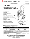
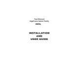
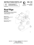
INSTRUCTIONS-PARTS LIST
This manual contains important
warnings and information.
READ AND KEEP FOR REFERENCE.
307–830
Rev. F
Supersedes Rev. E
First choice when
quality counts.
INSTRUCTIONS
EM590 Airless Paint Sprayer
2750 psi (190 bar, 19 MPa) Maximum Working Pressure
Model 220–856, Series D
Basic sprayer on Upright cart without hose or gun
Model 231–590, Series A
Same as 220–856 and includes 50 ft (15.1 m) hose,
3 ft (0.9 m) whip hose and spray gun with RAC IV
DripLess Tip Guard and 517 size SwitchTip
01744C
GRACO INC.
P.O. BOX 1441 MINNEAPOLIS, MN
http://www.graco.com
COPYRIGHT 1987, GRACO INC.
Graco Inc. is registered to I.S. EN ISO 9001
55440–1441
Table of Contents
Warnings . . . . . . . . . . . . . . . . . . . . . . . . . . . . . . . . . . . . . . 2
Setup . . . . . . . . . . . . . . . . . . . . . . . . . . . . . . . . . . . . . . . . . 5
Startup . . . . . . . . . . . . . . . . . . . . . . . . . . . . . . . . . . . . . . . 7
Maintenance . . . . . . . . . . . . . . . . . . . . . . . . . . . . . . . . . . 8
Flushing . . . . . . . . . . . . . . . . . . . . . . . . . . . . . . . . . . . . . . 9
Application Methods . . . . . . . . . . . . . . . . . . . . . . . . . . . 10
Troubleshooting . . . . . . . . . . . . . . . . . . . . . . . . . . . . . . . 11
Motor Brush Replacement . . . . . . . . . . . . . . . . . . . . . . 13
Displacement Pump . . . . . . . . . . . . . . . . . . . . . . . . . . . 14
Connecting Rod and Bearing Housing . . . . . . . . . . . 15
Drive Housing . . . . . . . . . . . . . . . . . . . . . . . . . . . . . . . .
Motor . . . . . . . . . . . . . . . . . . . . . . . . . . . . . . . . . . . . . . . .
Pressure Control . . . . . . . . . . . . . . . . . . . . . . . . . . . . . .
Pressure Control Adjustment . . . . . . . . . . . . . . . . . . .
Parts – Pressure Control . . . . . . . . . . . . . . . . . . . . . . .
Parts – Upright Sprayer . . . . . . . . . . . . . . . . . . . . . . . .
Technical Data . . . . . . . . . . . . . . . . . . . . . . . . . . . . . . . .
Graco Phone Number . . . . . . . . . . . . . . . . . . . . . . . . . .
Accessories . . . . . . . . . . . . . . . . . . . . . . . . . . . . . . . . . .
Graco Warranty . . . . . . . . . . . . . . . . . . . . . . . . . . . . . . .
16
17
19
21
23
25
27
27
27
28
Symbols
Warning Symbol
Caution Symbol
WARNING
CAUTION
This symbol alerts you to the possibility of serious
injury or death if you do not follow the instructions.
This symbol alerts you to the possibility of damage to
or destruction of equipment if you do not follow the
instructions.
WARNING
FIRE AND EXPLOSION HAZARD
Improper grounding, poor ventilation, open flames or sparks can cause a hazardous condition and
result in a fire or explosion and serious injury.
If there is any static sparking or you feel an electric shock while using this equipment, stop spraying immediately. Do not use the equipment until you identify and correct the problem.
Provide fresh air ventilation to avoid the buildup of flammable fumes from solvents or the fluid
being sprayed.
Keep the spray area free of debris, including solvent, rags, and gasoline.
Electrically disconnect all equipment in the spray area.
Extinguish all open flames or pilot lights in the spray area.
Do not smoke in the spray area.
Do not turn on or off any light switch in the spray area while operating or if fumes are present.
Do not operate a gasoline engine in the spray area.
Use only with a grounded outlet that matches the grounded plug of this equipment.
WARNING
INJECTION HAZARD
Spray from the gun, leaks or ruptured components can inject fluid into your body and cause extremely
serious injury, including the need for amputation. Fluid splashed in the eyes or on the skin can also
cause serious injury.
Fluid injected into the skin is a serious injury. The injury may look like just a cut, but it is a serious
injury. Get immediate medical attention.
Do not point the gun at anyone or at any part of the body.
Do not put your hand or fingers over the spray tip.
Do not stop or deflect leaks with your hand, body, glove or rag.
Do not “blow back” fluid; this is not an air spray system.
Always have the tip guard and the trigger guard on the gun when spraying.
Check the gun diffuser operation weekly. Refer to the gun manual.
Be sure the gun trigger safety operates before spraying.
Lock the gun trigger safety when you stop spraying.
Follow the Pressure Relief Procedure on page 11 if the spray tip clogs and before cleaning,
checking or servicing the equipment.
Tighten all fluid connections before operating the equipment.
Check the hoses, tubes, and couplings daily. Replace worn or damaged parts immediately. Do not
repair high pressure couplings; you must replace the entire hose.
Fluid hoses must have spring guards on both ends, to help protect them from rupture caused by
kinks or bends near the couplings.
TOXIC FLUID HAZARD
Hazardous fluid or toxic fumes can cause serious injury or death if splashed in the eyes or on the skin,
inhaled, or swallowed.
Know the specific hazards of the fluid you are using.
Store hazardous fluid in an approved container. Dispose of hazardous fluid according to all local,
state and national guidelines.
Always wear protective eyewear, gloves, clothing and respirator as recommended by the fluid and
solvent manufacturer.
MOVING PARTS HAZARD
Moving parts can pinch or amputate your fingers.
Keep clear of all moving parts when starting or operating the pump.
Before servicing the equipment, follow the Pressure Relief Procedure on page 11 to prevent the
equipment from starting unexpectedly.
WARNING
EQUIPMENT MISUSE HAZARD
Equipment misuse can cause the equipment to rupture or malfunction and result in serious injury.
INSTRUCTIONS
This equipment is for professional use only.
Read all instruction manuals, tags, and labels before operating the equipment.
Use the equipment only for its intended purpose. If you are not sure, call your distributor.
Do not alter or modify this equipment. Use only genuine Graco parts.
Check equipment daily. Repair or replace worn or damaged parts immediately.
Do not exceed the maximum working pressure of the lowest rated system component. Refer to the
Technical Data on page 27 for the maximum working pressure of this equipment.
Use fluids and solvents which are compatible with the equipment wetted parts. Refer to the Technical Data section of all equipment manuals. Read the fluid and solvent manufacturer’s warnings.
Do not use 1,1,1–trichloroethane, methylene chloride, other halogenated hydrocarbon solvents or
fluids containing such solvents in pressurized aluminum equipment. Such use could result in a
chemical reaction, with the possibility of explosion.
Do not use hoses to pull equipment.
Route hoses away from traffic areas, sharp edges, moving parts, and hot surfaces. Do not expose
Graco hoses to temperatures above 82C (180F) or below –40C (–40F).
Do not lift pressurized equipment.
Comply with all applicable local, state, and national fire, electrical, and safety regulations.
NOTE: This is an example of the DANGER label on
your sprayer. This label is available in other
languages, free of charge. See page 27 to order.
FIRE AND
EXPLOSION HAZARD
SKIN INJECTION
HAZARD
Spray painting, flushing or cleaning equipment with flammable liquids in
confined areas can result in fire or explosion.
Liquids can be injected into the body by high pressure airless spray or
leaks – especially hose leaks.
Use outdoors or in extremely well ventilated areas. Ground equipment,
hoses, containers and objects being sprayed.
Keep body clear of the nozzle. Never stop leaks with any part of the
body. Drain all pressure before removing parts.Avoid accidental triggering of gun by always setting safety latch when not spraying.
Avoid all ignition sources such as static electricity from plastic drop
cloths, open flames such as pilot lights, hot objects such as cigarettes,
arcs from connecting or disconnecting power cords or turning light
switches on and off.
Failure to follow this warning can result in death or serious injury.
Never spray without a tip guard.
In case of accidental skin injection, seek immediate
“Surgical Treatment”.
Failure to follow this warning can result in amputation or serious injury.
READ AND UNDERSTAND ALL LABELS AND INSTRUCTION MANUALS BEFORE USE
4
307-830
Setup
WARNING
To reduce the risk of serious bodily injury caused
by static sparking, fluid injection or over–pressurization and rupture of the hose or gun, all hoses
must be electrically conductive, the gun must have
a tip guard, and each part must be rated for at least
2750 psi (190 bar, 19 MPa) Working Pressure.
CAUTION
To avoid damaging the pressure control, which may
result in poor equipment performance and component damage:
1. Always use grounded, flexible spray hose (85) at
least 50 ft (15 m) long.
2. Never use a wire braid hose as it is too rigid to
act as a pulsation dampener.
3. Never install any shutoff device between the filter
(15) and the main hose. See Fig. 1.
WARNING
FIRE AND EXPLOSION HAZARD
Proper electrical grounding is essential
to reduce the risk of fire or explosion
which can result in serious bodily injury
and property damage. See the warning
section FIRE OR EXPLOSION HAZARD on page 2 for more detailed
grounding instructions.
1. Connect the hoses and gun to the sprayer. Use
a 1/4 in. ID, 50 ft (15 m) long (minimum) main
hose (85). For more flexible gun movement, install
a 3/16 in. ID, 3 ft (0.9 m) hose (86) between the
main hose and the gun (87). Don’t use thread
sealant, and don’t install the spray tip yet!
2. Fill the packing nut/wet-cup (221) 1/3 full with
Throat Seal Liquid (TSL), supplied.
3. Check the electrical service.
a. Electrical requirements: 120 VAC, 60 Hz,
15A (minimum).
b. Use a grounded electrical outlet located at
least 20 ft (6 m) from the spray area.
c.
Do not remove the grounding prong of the
power supply cord, and do not use an
ungrounded adapter.
d. Extension cord specifications: 15A, 3 wires,
grounding type. Note that long lengths reduce
sprayer performance. A maximum extension
cord length of 200 ft (60 m) is recommended.
4. Flush the pump to remove the oil left in to protect
pump parts after factory testing. See Flushing on
page 9.
5. Prepare the paint. Remove any paint skin. Stir
the paint thoroughly. Strain the paint through a fine
nylon mesh bag to remove particles that could clog
the filter, if used, or the spray tip.
307-830
5
Setup
114
Keep 1/3 full with TSL at all times
Never install any shutoff device here
15b
221
85
Fig. 1
6
307-830
86
87
01744C
Startup
Use this procedure to help you start and operate the
sprayer properly and safely.
WARNING
INJECTION HAZARD
To reduce the risk of serious bodily
injury, follow the Pressure Relief Procedure Warning on page 11 before checking or repairing any part of the spray system.
5. Check all fluid connections for leaks. Follow
the Pressure Relief Procedure on page 11 before
tightening connections.
6. Install the spray tip and tip guard. Engage the
trigger safety latch. Install the spray tip according
to the instructions supplied with it.
7. Adjust the spray pattern.
NOTE: Flush the sprayer if this is a first-time startup.
See page 9.
a. Increase the pressure slowly just until spray
from the gun is completely atomized. Use the
lowest pressure needed to get the desired
results. This reduces overspray and fogging,
decreases tip wear and extends sprayer life.
NOTE: See Fig. 3 except where noted.
b. If more coverage is needed, use a larger tip
rather than increasing the pressure.
c.
Test the spray pattern. Adjust the spray tip
pattern according to the instructions supplied
with the gun or tip.
1. Turn the pressure adjusting knob (A) fully
counterclockwise to minimum pressure.
2. Put the intake tube (3) in the fluid container.
Trigger safety latch shown engaged (SAFE)
Trigger safety latch shown disengaged (OFF SAFE)
3. Plug in the sprayer.
CAUTION
Do not run the pump without fluid in it for more than
30 seconds to avoid damage to the displacement
pump packings.
Fig. 2
WARNING
105a
FIRE AND EXPLOSION HAZARD
To reduce the risk of static sparking and
splashing when flushing, always remove
the spray tip from the gun and hold a
metal part of the gun firmly to the side of grounded
metal pail.
A
4. Prime the pump.
a. Open the pressure drain valve (44). Turn on the
sprayer switch (105a). Slowly turn the pressure
adjusting knob (A) clockwise until the sprayer
starts. When fluid comes from the valve close it.
b. Disengage the trigger safety latch. See Fig. 2.
Holding a metal part of the gun firmly against a
grounded metal pail, trigger the gun until all air
is forced out of the system and the paint flows
freely from the gun.
c.
Release the trigger and engage the trigger
safety latch.
44
3
Fig. 3
01745C
Maintenance
WARNING
INJECTION HAZARD
To reduce the risk of serious bodily
injury, follow the Pressure Relief Procedure Warning on page 11 before checking or repairing any part of the spray system.
5. For very short shutoff periods, leave the suction
tube in the paint, relieve pressure, and clean the
spray tip.
6. Flush the sprayer at the end of each work day
and fill it with mineral spirits to help prevent pump
corrosion and freezing. See page 9.
CAUTION
Cleaning a Clogged Tip
WARNING
To reduce the risk of serious bodily injury from from
fluid injection:
NEVER operate the spray gun with the tip guard
removed.
DO NOT hold your hand, body, or a rag in front of
the spray tip when cleaning or checking for a clog.
Always point the gun toward the ground or into a
pail.
To prevent pump corrosion, and to reduce the
chance of fluid freezing in the pump or pressure
control in cold weather, never leave water or any
type of paint in the sprayer when it is not in use.
Freezing can seriously damage the sprayer or result
in a loss of pressure or stalling.
7. Coil the hose and hang it on the hose rack
when storing it, even for overnight, to help protect
the hose from kinking, abrasion, coupling damage,
etc.
DO NOT try to “blow back” paint; this is NOT an air
spray sprayer.
A
1. Clean the front of the tip frequently. Follow the
Pressure Relief Procedure, page 11, first.
2. Follow the cleaning instructions given in your
separate gun or spray tip instruction manual.
Shutdown and Care
1. Keep the packing nut/wet-cup (221) 1/3 full of
TSL (Throat Seal Liquid, supplied) at all times to
help prevent fluid buildup on the piston rod and
premature wear of packings. Follow the Pressure
Relief Procedure, page 11, before adding TSL.
2. Keep the packing nut/wet-cup just tight
enough to stop leakage. See Fig. 5. Overtightening causes binding and excessive packing wear.
Follow the Pressure Relief Procedure, page 11.
Then use a round punch or brass rod and light
hammer to adjust the nut.
7460A
Fig. 4
15
221
3. Clean the fluid filter (15) often, and whenever
the sprayer is stored. Follow the Pressure Relief
Procedure, page 11, before cleaning the filter.
4. Lubricate the bearing housing (A) after every
100 hours of operation. Follow the Pressure
Relief Procedure, page 11. Remove the front
cover. Fill the bearing housing cavity with SAE 10
non-detergent oil. See Fig. 4.
Fig. 5
01748C
Flushing
NOTE: Several flushes may be required to clean the system and prepare it for the next fluid or storage. Use this
chart to determine the required flushes and use the procedure below for flushing.
*Use this category for flushing a brand new sprayer and flushing after storage.
System
y
has this
fluid in it:
Next fluid to be
sprayed:
*Oil-based solvent
or paint
Flushing order
Before yyou spray
p y or store
sprayer:
Flush 1
Flush 2
Flush 3
Oil-based paint –
new color
Mineral spirits
none
none
Prime with oil
Oil-based solvent or
paint
Water-based paint
Mineral spirits
Warm soapy
water
Clean water
Prime with water
Oil-based solvent or
paint
Prepare for storage
Mineral spirits
none
none
Relieve pressure
Leave drain valve open
Water or waterbased paint
Water–based
paint – new color
Warm soapy
water
Clean water
none
Prime with water
Water or waterbased paint
Oil-based paint
Warm soapy
water
Clean water
Mineral spirits
Prime with oil
Water or waterbased paint
Prepare for storage
Warm soapy
water
Clean water
Mineral spirits
Relieve pressure
Leave drain valve open
WARNING
INJECTION HAZARD
To reduce the risk of serious bodily
injury, follow the Pressure Relief Procedure Warning on page 11 before checking or repairing any part of the spray system.
CAUTION
NEVER allow water or water–base material to freeze
in the pressure control. Doing so prevents the
sprayer from being started and causes serious
damage to the pressure control. Pump the water out
with mineral spirits.
4. Remove the spray tip from the gun.
5. Put the suction tube into a grounded metal pail
with 1/2 gallon of compatible solvent.
6. Start the sprayer. See page 7. To save the fluid in
the sprayer as you start to flush, trigger the gun
into another container until the next fluid appears,
then trigger the gun back into the fluid you are
pumping. Circulate the flushing fluid a couple of
minutes to thoroughly clean the system.
7. Raise the suction tube and trigger the gun to force
solvent from the hose. Do not run the pump dry for
more than 30 seconds to avoid damaging the
pump packings! Relieve pressure.
8. Remove the suction tube and clean separately.
WARNING
FIRE AND EXPLOSION HAZARD
To reduce the risk of static sparking and
splashing when flushing, always remove
the spray tip from the gun and hold a
metal part of the gun firmly to the side of grounded
metal pail.
9. Install the filter screen. Hand tighten the bowl.
A
C
B
1. Relieve pressure. Engage the trigger safety latch.
D
2. Remove the filter bowl (B) and screen (C). Reinstall the bowl and support (D) only. Clean the
screen separately.
3. Turn the pressure adjusting knob (A) fully counterclockwise to the minimum pressure.
44
01749A
Fig. 6
307-830
9
Application Methods
Hold the gun perpendicular to the surface. Keep the
gun at an even 12 to 14 in. (300 to 356 mm) from the
surface you are spraying. See Fig. 7.
Begin moving the gun horizontally at a steady rate.
Start the spray stroke off the target surface and pull
the trigger as the gun is moving. Then, while the gun is
still moving, and as you approach the other edge of the
surface, release the trigger. This method avoids excess paint buildup at the end of each stroke.
The best way to control the rate of coverage is with the
gun tip size. A small tip orifice applies less paint. A
larger tip orifice applies more paint. The width of the
pattern depends on the fan pattern of the tip you
choose.
Do not try to increase coverage by increasing the fluid
pressure! Use the lowest pressure needed for good
results. This prolongs the life of your sprayer and
reduces paint lost by overspray.
For interior corners aim the gun toward the center of
the corner to be sprayed. By dividing the spray pattern
this way, the edges on both sides are sprayed evenly.
See Fig. 9.
RIGHT
Fig. 9
Fig. 7
WRONG
0673
0072
Move the gun at a speed that provides a full, wet
coating to be applied without runs or sags. Lap each
stroke 50% over the previous stroke to produce a
uniform paint thickness. Spray in a uniform pattern
from right to left and then left to right for a professional
finish. See Fig. 8.
If there is a wind, angle the spray pattern into the wind
to minimize drifting. Paint from the ground to the roof.
Shrubs. Tie back shrubs with rope and stakes. Cover
them with a dropcloth as the painter approaches the
area. Remove the dropcloth as soon as the area is
painted to prevent damage.
Concrete walks. If the walkways will be walked on,
cover them with a canvas dropcloth to avoid slipping.
Otherwise a plastic cloth can be used.
Electrical outlets and lamps. Protect electrical outlets
with masking tape. Cover lamps with plastic bags
secured with masking tape.
OVERLAP EACH STROKE 50%
Fig. 8
10
307-830
0672
Nearby objects. Move portable objects upwind of the
surface to be sprayed. If there is a nearby home, make
a protective barrier by hanging plastic drop cloths
between two long poles.
Troubleshooting
WARNING
Pressure Relief Procedure
5. Engage the gun safety latch.
To reduce the risk of serious bodily injury always
follow this procedure before checking or repairing the
sprayer.
1. Engage the gun safety latch.
6. Open the pressure drain valve. Leave the valve
open until you are ready to spray again.
2. Turn the ON/OFF switch to OFF.
3. Unplug the power supply cord.
4. Disengage the gun safety latch. Hold a metal part
of the gun firmly to the side of a grounded metal
pail, and trigger the gun to relieve pressure.
If you suspect that the spray tip or hose is completely
clogged, or that pressure has not been fully relieved
after following the steps above, VERY SLOWLY
loosen the tip guard retaining nut or hose end coupling to relieve pressure gradually, then loosen
completely. Now clear the tip or hose.
Check everything in the chart before disassembling the sprayer.
PROBLEM
CAUSE
SOLUTION
Electric motor won’t run
Power cord or extension cord unplugged or damaged, or building circuit breaker or fuse has tripped
Check, reset or replace.
Motor overload switch1 has opened
Unplug sprayer, relieve pressure, allow
motor to cool, decrease pressure.
Pressure setting too low
Increase pressure.
Pressure control frozen or damaged
by over–pressurization
Try to thaw2, or replace pressure control.
Power cord or extension cord unplugged, or damaged, or building
circuit or fuse is blown
Check, reset or replace.
Motor overload switch1 has opened
Unplug sprayer, relieve pressure, allow
motor to cool, clear motor air passages of
dirt and overspray; decrease pressure.
Pressure setting too low
Increase pressure.
Spray tip plugged
Remove and clean.
Wrong type extension cord
Use maximum 200 ft (61 m), 3 wire,
12 gauge, grounded extension cord.
Piston ball check not seating
Service pump. See page 14.
Piston packings worn or damaged
Replace piston. See page 14.
Intake valve ball check not seating
Service pump. See page 14.
Pump is frozen
Thaw2
Pressure control frozen or damaged
by overpressurization3
Try to thaw2, or replace pressure control.
Drive assembly damaged
Replace drive housing. See page 16.
Pump worn or damaged
Replace pump. See page 14.
Sprayer is not primed.
Follow the procedure on page 7 again.
Electric motor stops while
spraying
Electric motor runs, but low
paint output or no paint output, and pump is not stroking
See the PROBLEM, “Not
enough paint pressure”,
pressure” on
page
p
g 12,, also.
307-830
11
Troubleshooting
PROBLEM
CAUSE
SOLUTION
Paint leaks into wet-cup
Packing nut is loose
Tighten. See page 8.
Throat packings are worn or
damaged
Replace packings. See page 14.
Spray tip or fluid filter is plugged
Disassemble and clean.
Spray tip too big or worn
Change spray tip.
Paint too viscous
Thin the paint.
Wrong type hose
Use minimum 50 ft (15 m), grounded, flexible hose (wire braid hose is
unacceptable).
Pressure setting too low
Increase the pressure.
Spray tip too big or worn
Change the spray tip.
Pressure control frozen or damaged
by overpressurization3
Try to thaw2, or replace pressure control.
Pump worn or damaged
Replace pump. See page 14.
Pressure setting too low
Increase pressure.
Fluid outlet filter (if used) is dirty or
clogged
Clean filter. See instructions supplied
with it.
Spray tip too big or worn
Change spray tip.
Fluid supply is low or empty
Refill and prime pump. Check fluid supply
often to prevent running pump dry.
Paint too viscous
Thin paint.
Wrong type hose
Use minimum 50 ft (15 m), grounded, flexible hose (wire braid hose is
unacceptable).
Paint runs or sags
Spray tip to big or worn
Change spray tip.
Spitting from gun
Air in fluid pump or hose
Check for loose connections at pump
intake and tighten. Then prime pump.
Spray tip is partially clogged
Clear tip. See page 8.
Fluid supply is low or empty
Refill and prime pump. Check fluid supply
often to prevent running pump dry.
Spray or work being sprayed is not
properly grounded
Correct problem before continuing. Follow
the warning section, FIRE OR EXPLOSION HAZARD on page 2.
Excessive surging from spray
gun
Not enough paint pressure
Tails or fingers in spray
pattern
Static sparking from gun
1 The electric motor has an over-temperature switch
which automatically resets upon cooling. If it opens and
the electric motor shuts itself off, unplug the power supply
cord and let the sprayer cool for 30 to 60 minutes. Always
use the lowest pressure setting needed when spraying.
Prevent overspray from restricting the motor air passages; check and clean often.
2 Freezing
results from failure to replace the water-base
paint or flushing water with mineral spirits, and usually
causes permanent damage to the pressure control.
12
307-830
3 Over-pressurization
results from (1) using less than 50
ft (15 m) of flexible spray hose, (2) from using a wire braid
spray hose, (3) from adding a shutoff device between the
pump outlet and the spray gun, (4) from attaching a spray
hose to the pressure drain valve, or (5) from using a
clogged or incorrectly assembled filter, if used.
Motor Brush Replacement
NOTE: Replace the brushes when they have worn to
less than 10 mm. See Fig. 12. Always replace both
brushes at the same time. A Brush Repair Kit, 220–853,
and spring clip, 110–816, are available.
NOTE: Replacement brushes may last only half as long
as the original ones. To maximum brush life, break in new
brushes by operating the sprayer with no load (remove
the pump connecting rod pin) for at least one hour.
9. Test the brushes. Remove the connecting rod pin
(50). See 15, page 14. With the sprayer off, turn
the pressure control knob fully counterclockwise to
minimum pressure. Plug in the sprayer. Turn the
sprayer on. Slowly increase the pressure until the
motor is at full speed. Inspect the brush and
commutator contact area for excessive arcing.
Arcs should not “trail” or circle around the commutator surface.
CAUTION
A
Do not touch the brushes, leads, springs or brush
holders while the sprayer is plugged in, to reduce the
risk of electric shock and serious bodily injury.
10. Install the brush inspection plates, gaskets and
covers.
11. Break in the brushes. Operate the sprayer for at
least one hour with no load. Then reinstall the
connecting rod pin (50).
2
B
01745C
Fig. 10
WARNING
INJECTION HAZARD
To reduce the risk of serious bodily
injury, follow the Pressure Relief Procedure Warning on page 11 before checking or repairing any part of the spray system.
1
Order part
no. 110–816
2
Hook of spring clip
C
D
1
01227
Fig. 11
D
B
C
1. Remove both inspection covers (A). See Fig. 10.
2. Push in the spring clip (E) to unhook it, and then
pull it out. See Fig. 11.
3. Loosen the terminal screw (F). Pull the brush lead
(E) away, leaving the motor lead (G) in place.
Remove the brush (C) and spring (B). See Fig. 12.
4. Inspect the commutator for excessive pitting,
burning or gouging. A black color on the commutator is normal. Have the commutator resurfaced by
a qualified motor repair shop if the brushes seem
to wear too fast.
5. Install the new brush (C) so its lead is in the long
slot (H) of the holder. See Fig. 13. Slide the terminal (E) under the terminal screw washer. Make
sure the motor lead (G) is still connected the at the
screw. Tighten the screw (F). See Fig. 12.
1
1
10 mm minimum
E
F
Fig. 12
1
Spring
must
coil in this
direction
G
01227
H
B
1
C
D
6. Place the spring (B) on the brush as shown in Fig.
13. The spring must coil as shown.
7. Push in and hook the spring clip (D). See Fig. 13.
8. Repeat for the other side.
Fig. 13
307-830
13
Displacement Pump
Repairing the pump
52
See manual 307–806 for pump repair instructions.
A
Reinstalling the pump See Fig. 14 and 15.
1. Rotate the crankshaft (A) so the connecting rod is
in its lowest position.
2. The pump piston rod (223) should protrude about
1 in. (25 mm) above the pump cylinder.
49
223
51
50
30
32
3. Screw the pump into the bearing housing (51) until
its pin hole is aligned with the connecting rod (52)
pin hole. Insert the pin (50). Position the spring
(49) so it covers the ends of the pin. See Fig. 15.
6
WARNING
4
76
222
Be sure the retaining spring (49) is firmly and completely in the groove of the connecting rod to prevent
the pin (50) from working loose due to vibration.
3
If the pin works loose, it or other parts could break off
due to the force of the pumping action, resulting in
serious bodily injury, pump or property damage.
75
74
Torque to
80 ft–lb (107 N.m)
01746B
Fig. 14
4. Adjust the pump so the cylinder’s top threads are
flush with the face (B) of the bearing housing and
the outlet nipple (32) is straight back. See Fig. 15.
5. Torque the locknut (6) to 80 ft-lb (107 N.m).
WARNING
6. Reassemble the remaining parts, in the reverse
order of removal.
INJECTION HAZARD
To reduce the risk of serious bodily
injury, follow the Pressure Relief Procedure Warning on page 11 before checking or repairing any part of the spray system.
50
49
Removing the pump See Fig. 14.
1. Flush the sprayer. Relieve pressure.
52
2. Remove the clips (74,76) and drain hose (75).
51
3. Hold the intake valve (222) steady with a wrench
and unscrew the suction tube (3).
B
4. Use a screwdriver to push the retaining spring (49)
up, and then push out the pin (50).
5. Loosen the locknut (6). Unscrew the pump (4).
32
Fig. 15
01751A
Connecting Rod and Bearing Housing
WARNING
INJECTION HAZARD
To reduce the risk of serious bodily
injury, follow the Pressure Relief Procedure Warning on page 11 before checking or repairing any part of the spray system.
10. Align the connecting rod (52) with the crank (C)
and push the bearing housing (51) onto the drive
housing (14).
11. Assemble the remaining parts. Refer to page 14 to
reinstall the pump.
NOTE: Refer to Fig. 16.
Detail A
1. Remove the pail hanger (7).
2. Remove the front cover (12).
3. Remove the pump as described on page 14.
A
B
4. Remove the four screws (9) and lockwashers (10).
Pull the bearing housing (51) and connecting rod
assembly (52) off the crankshaft (C).
14
C
5. Clean and inspect the crankshaft (C). Wipe it clean
with a rag (don’t use solvent). If the crankshaft is
badly worn, replace the drive assembly (14). See
page 21.
6. Clean and inspect the bearing housing (51) and
connecting rod (52), including the needle bearing
(A). Replace both parts if either is worn or damaged. See Detail A.
52
9
12
13
7. Clean the mating surfaces of the bearing and drive
housings.
5
49
CAUTION
To extend the service life of the connecting rod
bearing, lubricate it properly. After every 100 hours of
operation, or whenever servicing the pump (whichever comes first), fill the cavity (B) in the connecting
rod with SAE non-detergent motor oil. See Detail A.
10
51
50
7
6
30
32
8. Coat the surfaces of the connecting rod and bearing with SAE non-detergent motor oil. Liberally
pack the needle bearing (A) with industrial grade,
heavy duty, extreme pressure, lithium soap
grease. See Detail A.
9. Assemble the connecting rod (52) and bearing
housing (51).
Fig. 16
01750B
Drive Housing
5. Lightly tap the lower rear of the drive housing (14)
with a plastic mallet to loosen it from the motor
(16). Pull the drive housing (14) off the motor.
WARNING
INJECTION HAZARD
To reduce the risk of serious bodily
injury, follow the Pressure Relief Procedure Warning on page 11 before checking or repairing any part of the spray system.
CAUTION
DO NOT drop the gear cluster (56) when removing
the drive housing (14). The gear may stay engaged
in the motor or drive housing.
NOTE: Refer to Fig. 17 for this procedure.
NOTE: Stop the sprayer at the bottom of its stroke to
get the crank (C) in its lowest position. To lower it
manually, carefully rotate the blades of the fan with a
screwdriver.
DO NOT lose the thrust balls (14c, 16b), or allow
them to fall between the gears. The balls, heavily
covered with grease, usually stay in the shaft
recesses, but could become dislodged. If caught
between gears and not removed, the balls will seriously damage the drive housing. If they are not in
place, the bearings will wear prematurely.
1. Remove the front cover (12).
2. Remove the four screws (9). Lightly tap the lower
rear of the bearing housing (51) with a plastic
mallet to loosen it from the drive housing (14). Pull
the bearing housing/connecting rod/pump
assembly off the drive housing (14).
6. Liberally apply bearing grease to the gear cluster
(56). Be sure the thrusts balls (14c,16b) are in place.
3. Remove the screws (42) from the recess of the
drive housing (14). Remove the screws (72,53)
from the rear of the motor’s front end bell.
7. Place the dark washer (14b) and then the light one
(14a) on the shaft protruding from the big gear in
the drive housing. Align the gears and push the
new drive housing straight onto the motor and its
locating pins.
4. Remove the screws (53) from the rear of the
motor’s front end bell.
8. Continue reassembling the sprayer.
54
53
16
14a
16b
56
14b
14
14c
C
A
51
9
10
12
13
Fig. 17
01752C
Motor
WARNING
INJECTION HAZARD
To reduce the risk of serious bodily
injury, follow the Pressure Relief Procedure Warning on page 11 before checking or repairing any part of the spray system.
NOTE: Refer to Fig. 18.
1. Remove the four screws (13) and front cover (12).
Disconnect the hose (30) and drain hose (80).
2. Remove the pressure control cover (21). Disconnect the four motor leads.
3. Unscrew the connector nut (103) at the pressure
control. Swing the conduit (27) away from the
connector.
4. Remove the conduit seal (18) from around the
wires in the pressure control. Pull the motor leads
through the elbow, one at a time.
CAUTION
Always pull the motor leads one at a time to avoid
loosening the terminals.
5. Loosen the nut of the connector (25) at the motor.
Pull the conduit (27) away from the motor and then
pull the wires through the conduit, one at a time.
6. Remove the connector (25) elbow from the motor,
and then pull the wires through it one at a time.
7. Remove the screws (42) from the recess of the
drive housing (14). Remove the screws (72) and
washers (54) from the rear of the motor’s front end
bell.
8. Remove the screws (53) and washers (54) from
the rear of the motor’s front end bell.
9. Lightly tap the lower rear of the drive housing (14)
with a plastic mallet to loosen the assembly from
the motor (16). Pull the drive housing assembly off
the motor.
CAUTION
DO NOT drop the gear cluster (56) when removing
the drive housing (14). The gear may stay engaged
in the motor or drive housing.
DO NOT lose the thrust balls (14c, 16b), or allow
them to fall between the gears. The balls, heavily
covered with grease, usually stay in the shaft
recesses, but could become dislodged. If caught
between gears and not removed, the balls will seriously damage the drive housing. If they are not in
place, the bearings will wear prematurely.
10. While supporting the motor to keep the sprayer
from tipping, remove the capscrews (35) which
hold the motor to the cart. Lift the motor off the
cart.
11. Mount the new motor to the cart.
12. Liberally apply bearing grease to the gear cluster
(56). Be sure the thrusts balls (14c,16b) are in
place.
13. Place the dark washer (14b) and then the light one
(14a) on the shaft protruding from the big gear in
the drive housing. Align the gears and push the
new drive housing straight onto the motor and its
locating pins.
14. Continue reassembling the sprayer. Follow the
NOTE and WARNING, below.
NOTE: Use a turning motion on the conduit when
feeding wires through it.
WARNING
All wires connected to the over-pressure switch (C)
and the pressure switch (D) must be insulated at
the terminals to reduce the risk of electric shock if
someone touches these parts when the power is
on. When installing the new pressure control, be
sure these terminals are covered with shrink tubing
or electrical tape.
307-830
17
Motor
ÇÇÇ
ÉÉ ÉÉÉ
ÉÉ
Partial Wiring
Diagram
C
Conduit Seal Detail
1
D
18
3
103
2
2
103
53
1
All wires to the over-pressure switch (C) and
the pressure switch (D) must be insulated
with shrink tubing or electrical tape.
2
Motor leads
3
Conduit seal (18) shown installed in conduit connector (103)
4
See Detail above
16
54
35
14a
16b
25
56
14b
21
14c
14
70
10
9
103
12
13
34
33
27
30
4
Fig. 18
80
01754C
4
Pressure Control
WARNING
INJECTION HAZARD
To reduce the risk of serious bodily
injury, follow the Pressure Relief Procedure Warning on page 11 before checking or repairing any part of the spray system.
CAUTION
Do not remove the nipple (105e) or elbow (105d)
from the pressure control unless they are damaged.
Twisting or jarring the these fittings could alter the
factory setting of the control or permanently damage
it. If they must be removed, use extreme care. Hold
the corresponding hex (B) steady with a wrench and
then remove the part.
WARNING
All wires connected to the over–pressure switch (C)
and the pressure switch (D) must be insulated at
the terminals to reduce the risk of electric shock if
someone touches these parts when the power is
on. When installing the new pressure control, be
sure the these terminals are covered with shrink
tubing or electrical tape. See Fig. 20.
8. Remove the mounting screws (35) and pull the
pressure control away from the sprayer.
See Fig. 19.
9. Remove the mounting plate (11) and secure it to
the new pressure control. See Fig. 19.
10. Reassemble the new pressure control in the
reverse order of disassembly.
11. Adjust the pressure control. See page 21.
CAUTION
Failure to observe the following precautions may
cause poor performance or excessive pressure and
permanent damage to the pressure control.
Always use at least 50 ft (15.2 m) of grounded,
flexible spray hose.
Never use a wire braid spray hose.
Never add any type of shutoff device between the
pump outlet and the spray gun.
Check the filter (if used) for clogging or incorrect
assembly if tip clogging frequency increases.
Never allow flushing water or water base paint to
freeze in the system.
1. Disconnect the spray hose. Hold the nut (B)
steady with a wrench and unscrew the filter (15).
11
35
23
2. Hold the elbow (105d) steady with a wrench and
disconnect the hose (30). Disconnect the drain
hose (80).
3. Remove the pressure control cover (21).
21
34
33
4. Disconnect the three power supply cord leads. See
Fig. 20.
B
101
15
70
103
105e
105d
5. Disconnect the four motor leads. See Fig. 20.
6. Unscrew the conduit nut (103). See Fig. 19. Pull
the pressure control away from the conduit while
carefully guiding the wires through the connector.
80
7. Loosen the knurled part of the strain relief bushing
(101) and unscrew the fitting from the pressure
control. See Fig. 19.
30
44
01755A
Fig. 19
Pressure Control
ÇÇÇÇ
ÇÇÇÇ
ÉÉ
ÉÉ
C
D
ÉÉÉÉ ÉÉÉÉ
RED
WHITE
2
Motor leads
3
Power supply leads
All wires to the over-pressure
switch (C) and the pressure
switch (D) must be insulated with
shrink tubing or electrical tape.
1
1
3
ÉÉ
ÉÉ
ÎÎ
ÎÎ
ÎÎ
ÎÎ
102
101
68
18
2
130
Fig. 20
01314
Pressure Control Adjustment
WARNING
USE EXTREME CAUTION WHEN PERFORMING
THIS ADJUSTMENT PROCEDURE to reduce the
risk of a fluid injection injury or other serious bodily
injury, which can result from component rupture,
electric shock, fire, explosion or moving parts.
This procedure sets the sprayer to 2750 psi (190 bar)
MAXIMUM WORKING PRESSURE.
NEVER attempt to increase the sprayer’s maximum
working pressure by performing these adjustments in
any other way. Normal operation of the sprayer at
higher pressures may result in component rupture,
fire or explosion. To perform this adjustment, however, the sprayer pressure must be temporarily increased above the normal working pressure.
Perform this procedure whenever the microswitch or
pressure control assembly is reinstalled or replaced.
Improper calibration can cause the sprayer to overpressurize, resulting in component rupture, fire or
explosion. It may also prevent the sprayer from
obtaining the maximum working pressure, resulting in
poor sprayer performance.
Service Tools Needed
Use a new 50 foot (15.2 m) spray hose, rated for at
least 3000 psi (210 bar) MAXIMUM WORKING
PRESSURE, when performing this procedure. A
used, under–rated hose could develop a high pressure leak or rupture.
Procedure
See Fig. 21.
NEW 50 foot, 3000 psi (minimum) grounded, flexible airless spray hose (A), 223–541
Nipple (B), 1/4 npt x 1/4 npsm, 162–453
Swivel (C), 1/4 npt(m) x 1/4 npsm swivel, 156–823
Tee (D), 1/4 npt(m), 104–984
0–5000 psi fluid–filled pressure gauge (E),1/4 npt,
102–814
Needle valve, 102–715 or 103–067
3/8 in. open end wrench
Mineral spirits
WARNING
INJECTION HAZARD
To reduce the risk of serious bodily
injury, follow the Pressure Relief Procedure Warning on page 11 before checking or repairing any part of the spray system.
1. Remove the old spray hose. Install the new hardware and hose as shown in Fig. 21. On the other
end of the hose install the needle valve.
Procedure continued on page 22
5 gallon pail and water
E
D
B
C
A
44
01315
Fig. 21
307-830
21
Pressure Control Adjustment
E
6. If the pressure is lower than 2750 psi (190 bar):
Unplug the sprayer and relieve pressure. Insert the
wrench through the hole (C) and tighten the adjustment nut (B) 1/8 turn or less. Repeat steps 5 and
6.
A
+
If the pressure is higher than 2750 psi (190 bar):
Unplug the sprayer and relieve pressure. Insert the
wrench through the hole (C) and loosen the pressure adjustment nut (B) 1/8 turn or less. Repeat
steps 5 and 6. Repeat this procedure until the
proper stall pressure is obtained.
7. Now check to see at what pressure the sprayer
starts to run again after it stalls. Plug in the sprayer, turn it on, close the needle valve, and set the
pressure at maximum. Allow the sprayer to run
until it stalls.
B
D
C
Fig. 22
TIGHTEN
68
0750
NOTE: Refer to Fig. 22 for the remainder of this
procedure.
2. Remove the plug (68).
3. Open the needle valve slightly. Turn the pressure
adjusting knob (A) to the minimum setting.
4. Plug in the sprayer and turn the switch (E) ON.
Increase the pressure just enough to start the
sprayer. Fully prime the hose, being sure to eliminate all air from the system.
5. Open the needle valve a just enough to allow the
pump to run continuously, and turn the pressure
adjusting knob to maximum. Very slowly start to
close the needle valve. Observe the pressure at
which the pump stalls, which should be approximately 2750 psi (190 bar).
NOTE: In Step 8, the slower the pressure is raised,
the easier it is to note the exact stall pressure. Closing
the needle valve quickly causes the pressure to rise
too fast which gives a false reading.
8. Open the needle valve very slowly while observing
the pressure gauge. Check to see if the pressure
drops to approximately 2350 psi (161 bar) before
the sprayer starts again.
9. If the pressure is not approximately 2350 psi (161
bar): Shut off and unplug the sprayer, but do not
relieve pressure. Turn the differential wheel (D)
just one notch and repeat Steps 5 and 6. Check
the pressure drop again, and repeat if necessary.
NOTE: If you adjust the differential wheel, recheck
the stall pressure (steps 5 and 6) to be sure the it has
not changed.
10. Relieve pressure. Flush the water out with mineral
spirits. Relieve pressure. Install the plug (68).
Remove the test equipment.
Parts – Pressure Control
Part No. 220–858
Pressure Control Assembly
Includes replaceable items
listed below
ÇÇÇÇ
ÇÇÇÇ
ÉÉ
ÉÉ
105c
104
105b
114
121
105a
105
ÉÉÉÉ ÉÉÉÉ
115
105f
105d
113,110,112
118
RED
WHITE
106,107
16d
105f
ÉÉ
ÉÉ
ÎÎ
ÎÎ
ÎÎ
ÎÎ
101
68
18
102
111
103
16c
120,107,119
103
See parts list on page 25
Ref
No.
Part No.
Description
101
102
103
104
105
108–295
220–945
108–460
183–466
220–905
105a
105b
105c
105d
105e
105f
106
107
105–679
107–255
105–659
100–840
157–350
162–453
100–035
157–021
STRAIN RELIEF BUSHING
POWER SUPPLY CORD, 8.5’
45 CONDUIT CONNECTOR
LABEL, Warning
PRESSURE CONTROL BOX, bare
Includes replaceable
items 105a to 105f
.ON/OFF SWITCH
.GUARD
.BOOT, on/off switch
.ELBOW, street, 1/4 npt(m x f)
.TEE, (2) 1/4 npt(f) x 1/4 npt (m)
.NIPPLE, 1/4 npt(m) x 1/4 nspm
SCREW, pan hd, no. 8 x 5/16”
LOCKWASHER, no. 8 internal
Qty
1
1
1
1
1
1
1
1
1
1
1
1
2
Ref
No.
Part No.
Description
110
111
112
113
114
115
118
119
120
121
100–072
220–924
103–181
107–070
107–254
107–256
218–916
108–783
100–284
218–168
NUT, hex, No. 6–32
VARISTOR/RECTIFIER
LOCKWASHER, no. 6
SCREW, flat hd, no. 6–32 x 5/8”
BOOT, circuit breaker
CIRCUIT BREAKER
TRIAC
SCREW, fil hd, no. 8–32 x 13/16”
NUT, hex, no. 8–32
JUMPER WIRE
Qty
2
1
2
2
1
1
1
1
1
2
Replacement Danger and Warning labels, tags and cards
are available at no cost.
Parts – Upright Sprayer
Model 220–856, Series D
Includes items 1 to 81
Detail A
20
14
Model 231–590, Series A
Includes items 1 to 87
52
11
23
35
15a
51
10
21
70
22,24
27
15
9
12,41
15b
13
5
7
43
Ref 30
49
81
Ref 75
44
30
Detail B
32
50
6
1g
4
76
1e
1d
16a
75
53
16
54
35
1f
25
74
14a
16b
56
3
2
53
14b
54
14c
See Detail A
1b
33
34
33
45
1a
48
86
85
87
1c
62
Parts – Upright Sprayer
Model 220–856, Series D
Includes items 1 to 81
Model 231–590, Series A
Includes items 1 to 87
Ref
No.
Part No.
Description
1
220–365
CART ASSEMBLY
Includes items 1a – 1g
.RETAINING RING
.WASHER, plain, 5/8”
.PLUG, plastic
.SPRING
.SNAP BUTTON
.SLEEVE
.CART HANDLE
KIT, strainer
INTAKE TUBE
DISPLACEMENT PUMP
See manual 307–806 for parts
RETAINER NUT
NUT, hex
PAIL HANGER
CAPSCREW, sch, 1/4–20 x 1”
LOCKWASHER, spring, 3/8”
MOUNTING BRACKET
DRIVE HOUSING COVER
SCREW, ovh, 8–32 x 3/8”
DRIVE HOUSING
Includes items 14a–14d
.WASHER, silver–colored
.WASHER, bronze–colored
.BALL, 1/4” sst
.GREASE
FLUID FILTER
Includes items 15a and 15b
See manual 307–273 for parts
.PLUG
.NIPPLE, 1/4 npsm x 1/4 npt
MOTOR
Includes items 16a–16d
.LABEL, Danger
.BALL, sst, 1/4”
.TERMINAL
.TERMINAL
CONDUIT SEAL (see page 23)
SCREW, ovh, 10–24 x 3/8”
PRESSURE CONTROL COVER
LABEL, identification
PRESSURE CONTROL
See page 23 for parts
LABEL, Warning
45CONDUIT CONNECTOR
1a
1b
1c
1d
1e
1f
1g
2
3
4
101–242
176–884
107–310
102–070
111–590
179–781
220–347
181–072
180–573
222–580
5
6
7
9
10
11
12
13
14
112–746
178–941
189–918
107–210
106–115
183–536
183–333
107–156
220–859
14a
14b
14c
14d
15
178–967
107–089
100–069
110–293
214–570
15a
15b
16
100–040
162–453
220–855
16a
16b
16c
16d
18
20
21
22
23
185–954
100–069
107–263
102–799
107–447
106–078
185–000
183–371
220–858
24
25
177–762
108–460
Qty
1
2
2
2
2
2
2
1
1
1
1
2
1
1
4
4
1
1
6
1
1
1
1
1
1
1
1
1
1
1
2
2
1
6
1
1
Ref.
No.
Part No.
Description
27
065–099
30
223–766
32
33
34
35
41
43
44
45
48
49
50
51
52
53
54
56
62
68
70
74
75
76
79
80
81
85
162–453
100–188
100–214
110–963
183–510
178–034
237–677
106–062
104–811
176–817
176–818
218–035
218–034
100–643
105–510
179–961
206–994
101–754
110–037
181–102
186–495
186–494
186–126
185–955
187–959
223–541
86
214–701
87
235–459
ELECTRICAL CONDUIT specify
length when ordering
9.5 in.
HOSE, nylon, 1/4” ID, cpld 1/4
nspm (fbe), 29” (740 mm) long,
spring guards both ends
1
NIPPLE, 1/4 npsm x 1/4 npt
1
7
NUT, hex, 5/16–18
7
LOCKWASHER, spring, 3/8”
CAPSCREW, hex hd, 5/16–18 x 7/8” 7
LABEL, identification
1
1
TAG, caution
PRESSURE RELIEF VALVE
1
WHEEL, semi–pneumatic
2
HUBCAP
2
RETAINING SPRING
1
PIN, hdless, 5/16” dia x 1”
1
BEARING HOUSING
1
CONNECTING ROD
1
6
CAPSCREW, sch, 1/4–20 x 1”
LOCKWASHER, 1/4”
6
GEAR REDUCER
1
THROAT SEAL LIQUID, 8 oz.
1
PLUG (See page 23)
1
SCREW
4
1
SPRING CLIP, large
DRAIN HOSE
1
1
SPRING CLIP, small
LABEL
1
LABEL, Danger
1
LABEL, Danger
1
HOSE, grounded,nylon, 1/4” ID,
cpld 1/4 npsm(f), 50 ft (15 m)
spring guards both ends
1
HOSE, grounded, nylon, 3/16” ID,
cpld 1/4 npsm(f), 3 ft (0.9 m) long,
spring guards both ends
1
SPRAY GUN
See manual 308–235 for parts
Includes RAC IV DripLess Tip Guard
and 517 size SwitchTip
1
Qty.
Replacement Danger and Warning labels, tags and cards
are available at no cost.
1
1
1
Notes
Technical Data
Electric Motor . . . . . . . . . . . . . . . . . . . . . . . . . . . . . . . 3/4 HP, DC
Electric Cord . . . . . . . . . . . . . . . . . . . . . . . . . . . . 14 AWG, 3 wire
Power Requirements . . . . . . . . . . . . . . . 120 VAC, 60 Hz, 15A
Maximum Working Pressure . . . . . . . . . . . 2750 psi (190 bar)
Maximum Delivery . . . . . . . . . . . . . . . . . . . . 0.75 gpm (2.8 lpm)
Cycles/Gallon (liter) . . . . . . . . . . . . . . . . . . . . . . . . . . . . 260 (70)
Tip Size . . . . . . . . . . . . . . . . . . . . . . . . . . . one gun to 0.025 tip
with latex at 2000 psi (138 bar)
Generator . . . . . . . . . . . . . . . . . . . . . . . . . . . . . 4000W minimum
Wetted Parts
Filter . . . . . . . . . . . . . . . . . . . . . . . . . . . . See manual 307–273
Displacement Pump . . . . . . . . . . . . . . . See manual 307–806
Sprayer . . . . . . . . . . . . . . . . . . . . Zinc–plated Carbon Steel,
Stainless Steel
Fluid Inlet . . . . . . . . . . . . . . . . 3/4 npt(m) with 30 ID chamfer
Fluid Outlet Size . . . . . . . . . . . . . . . . . . . . . . . . . . 1/4 npsm(m)
Dimensions
Weight . . . . . . . . . . . . . . . . 95 lb (43 kg)
Height . . . . . . . . . . . . 41 in. (1041 mm)
Length . . . . . . . . . . . . 20.5 in. (521 mm)
Width . . . . . . . . . . . . . 20.5 in. (521 mm)
NOTE: Delrin is a registered trademark of the DuPont Co.
Graco Phone
Number
TO PLACE AN ORDER, contact your Graco distributor, or call this number to identify the distributor
closest to you: 1–800–328–0211 Toll Free.
Accessories
Must Be Purchased Separately
Displacement Pump Repair 222–588
See contents in manual 307–806. Repair instructions are
included with the kit.
Motor Brush Replacement Kit, 220–853
See procedure on page 16.
DANGER LABELS
The English language DANGER label shown on page 4
is also on your sprayer. If you have painters who do not
read English, order one of the following labels to apply to
your sprayer. The drawing below shows the best placement of these labels for good visibility. Order the labels,
free of charge, by calling:1–800–328–0211
Apply other language in this area
on other side of motor
French
Spanish
German
Greek
Korean
English
185–955
185–962
186–042
186–046
186–050
185–954
01745C
Graco Warranty
Graco warrants all equipment listed in this manual which is manufactured by Graco and bearing its name to be free from defects in
material and workmanship on the date of sale by an authorized Graco distributor to the original purchaser for use. With the exception of
any special extended or limited warranty published by Graco, Graco will, for a period of twelve months from the date of sale, repair or
replace any part of the equipment determined by Graco to be defective. This warranty applies only when the equipment is installed,
operated and maintained in accordance with Graco’s written recommendations.
This warranty does not cover, and Graco shall not be liable for general wear and tear, or any malfunction, damage or wear caused by
faulty installation, misapplication, abrasion, corrosion, inadequate or improper maintenance, negligence, accident, tampering, or
substitution of non-Graco component parts. Nor shall Graco be liable for malfunction, damage or wear caused by the incompatibility of
Graco equipment with structures, accessories, equipment or materials not supplied by Graco, or the improper design, manufacture,
installation, operation or maintenance or structures, accessories, equipment or materials not supplied by Graco.
This warranty is conditioned upon the prepaid return of the equipment claimed to be defective to an authorized Graco distributor for
verification of the claimed defect. If the claimed defect is verified, Graco will repair or replace free of charge any defective parts. The
equipment will be returned to the original purchaser transportation prepaid. If inspection of the equipment does not disclose any defect
in material or workmanship, repairs will be made at a reasonable charge, which charges may include the costs of parts, labor, and
transportation.
Graco’s sole obligation and buyer’s sole remedy for any breach of warranty shall be as set forth above. The buyer agrees that no other
remedy (including, but not limited to, incidental or consequential damages for lost profits, lost sales, injury to person or property, or any
other incidental or consequential loss) shall be available. Any action for breach of warranty must be brought within two (2) years of the
date of sale.
GRACO MAKES NO WARRANTY, AND DISCLAIMS ALL IMPLIED WARRANTIES OF MERCHANTABILITY AND FITNESS FOR
A PARTICULAR PURPOSE IN CONNECTION WITH ACCESSORIES, EQUIPMENT, MATERIALS OR COMPONENTS SOLD BUT
NOT MANUFACTURED BY GRACO. These items sold, but not manufactured by Graco (such as electric motors, gas engines,
switches, hose, etc.), are subject to the warranty, if any, of their manufacturer. Graco will provide purchaser with reasonable assistance
in making any claim for breach of these warranties.
In no event will Graco be liable for indirect, incidental, special or consequential damages resulting from Graco supplying equipment
hereunder, or the furnishing, performance, or use of any products or other goods sold hereto, whether due to a breach of contract,
breach of warranty, the negligence of Graco, or otherwise.
FOR GRACO CANADA CUSTOMERS
The parties acknowledge that they have required that the present document, as well as all documents, notices and legal proceedings
entered into, given or instituted pursuant hereto or relating directly or indirectly hereto, be drawn up in English. Les parties
reconnaissent avoir convenu que la rédaction du présente document sera en Anglais, ainsi que tous documents, avis et procédures
judiciaires exécutés, donnés ou intentés à la suite de ou en rapport, directement ou indirectement, avec les procédures concernées.
ADDITIONAL WARRANTY COVERAGE
Graco does provide extended warranty and wear warranty for products described in the “Graco Contractor Equipment Warranty
Program”.
All written and visual data contained in this document reflects the latest product information available at the time of publication.
Graco reserves the right to make changes at any time without notice.
Sales Offices: Minneapolis, Detroit, Los Angeles
Foreign Offices: Belgium, Canada, England, Korea, France, Germany, Hong Kong, Japan
GRACO INC.
P.O. BOX 1441 MINNEAPOLIS, MN
55440–1441
http://www.graco.com
PRINTED IN U.S.A. 307–830 April 1987, Revised December 1997