1
INSTRUCTIONS-PARTS LIST
This manual contains IMPORTANT
WARNINGS and INFORMATION
READ AND RETAIN FOR REFERENCE
EM 390
307–724
Rev H
Supersedes Rev F
(and Rev G – not published)
PORTABLE/ELECTRIC
AIRLESS PAINT SPRAYER
2500 psi (172 bar) MAXIMUM WORKING PRESSURE
U.S. Patent No. 4,323,741
Upright Carts
Model 231–001, Series B
Basic sprayer, without hose or gun
Model 231–390
Complete sprayer with hose, “Flex” gun,
Reverse–A–Clean IV DripLess Tip Guard,
and 517 size SwitchTip, and is CSA listed
Model 231–018
Same as Model 231–390 except has “Contractor” gun
Lo–Boy Carts
Model 220–726, Series C
Basic sprayer, without hose or gun
Model 231–390 shown
Model 231–051
Complete sprayer with hose, “Flex” gun,
Reverse–A–Clean IV DripLess Tip Guard,
and 517 size SwitchTip, and is CSA listed
See Table Of Contents on page 36.
0663
NOTE: This is an example of the DANGER label on your sprayer.
This label is available in other languages, free of charge.
See page 33 to order.
FIRE AND
EXPLOSION HAZARD
Spray painting, flushing or cleaning equipment with flammable liquids in confined areas can result in fire or explosion.
Use outdoors or in extremely well ventilated areas. Ground equipment, hoses, containers and objects being sprayed.
Avoid all ignition sources such as static electricity from plastic drop
cloths, open flames such as pilot lights, hot objects such as cigarettes, arcs from connecting or disconnecting power cords or turning light switches on and off.
Failure to follow this warning can result in death or serious injury.
SKIN INJECTION
HAZARD
Liquids can be injected into the body by high pressure airless spray
or leaks – especially hose leaks.
Keep body clear of the nozzle. Never stop leaks with any part of the
body. Drain all pressure before removing parts.Avoid accidental triggering of gun by always setting safety latch when not spraying.
Never spray without a tip guard.
In case of accidental skin injection, seek immediate
“Surgical Treatment”.
Failure to follow this warning can result in amputation or serious
injury.
READ AND UNDERSTAND ALL LABELS AND INSTRUCTION MANUALS BEFORE USE
WARNINGS
HIGH PRESSURE SPRAY CAN CAUSE SERIOUS INJURY.
FOR PROFESSIONAL USE ONLY. OBSERVE ALL WARNINGS.
Read and understand all instruction manuals before operating the equipment.
FLUID INJECTION HAZARD
General Safety
Safety Latch
This equipment generates very high fluid pressure. Spray from
the gun, leaks or ruptured components can inject fluid through
your skin and into your body, and cause extremely serious bodily
injury, including the need for amputation. Also, fluid injected or
splashed into the eyes or on the skin can cause serious damage.
NEVER point the spray gun at any one or at any part of the body.
NEVER put your hand or fingers over the spray tip. NEVER try
to “blow back” paint; this is NOT an air spray system.
ALWAYS have the tip guard in place on the spray gun when
spraying.
ALWAYS follow the PRESSURE RELIEF PROCEDURE, below,
before cleaning or removing the spray tip or servicing any system equipment.
NEVER try to stop or deflect leaks with your hand or body.
Be sure equipment safety devices are operating properly before
each use.
Whenever you stop spraying, even for a moment, always set the
gun safety latch in the closed or “safe” position, making the gun
inoperative. Failure to set the safety latch can result in accidental
triggering of the gun.
Medical Alert––Airless Spray Wounds
If any fluid appears to penetrate your skin, get EMERGENCY
MEDICAL CARE AT ONCE. DO NOT TREAT AS A SIMPLE
CUT. Tell the doctor exactly what fluid was injected.
Note to Physician: Injection into the skin is a traumatic injury.
It is important to treat the injury surgically as soon as possible.
Do not delay treatment to research toxicity. Toxicity is a
concern with some exotic coatings injected directly into the
blood stream. Consultation with a plastic surgeon or reconstructive hand surgeon may be advisable.
Spray Gun Safety Devices
Be sure all gun safety devices are operating properly before
each use. Do not remove or modify any part of the gun; this can
cause a malfunction and result in serious bodily injury.
Diffuser
The gun diffuser breaks up spray and reduces the risk of fluid injection when the tip is not installed. Check the diffuser operation
regularly. Follow the PRESSURE RELIEF PROCEDURE, below, then remove the spray tip. Aim the gun into a metal pail, holding the gun firmly to the pail. Using the lowest possible pressure,
trigger the gun. If the fluid emitted is not diffused into an irregular
stream, replace the diffuser immediately.
Tip Guard
ALWAYS have the tip guard in place on the spray gun while
spraying. The tip guard alerts you to the fluid injection hazard
and helps reduce, but does not prevent, the risk of accidentally
placing your fingers or any part of your body close to the spray
tip.
Trigger Guard
Always have the trigger guard in place on the gun when spraying
to reduce the risk of accidentally triggering the gun if it is dropped
or bumped.
Spray Tip Safety
Use extreme caution when cleaning or changing spray tips. If the
spray tip clogs while spraying, engage the gun safety latch immediately. ALWAYS follow the PRESSURE RELIEF PROCEDURE, below, and then remove the spray tip to clean it.
NEVER wipe off build–up around the spray tip until the pressure
is fully relieved and the gun safety latch is engaged.
PRESSURE RELIEF PROCEDURE
To reduce the risk of serious bodily injury, including fluid injection,
splashing fluid or solvent in the eyes or on the skin, or injury from
moving parts or electric shock, always follow this procedure
whenever you shut off the sprayer, when checking or servicing
any part of the spray system, when installing, cleaning or changing spray tips, and whenever you stop spraying.
1. Engage the gun safety latch.
2. Turn the ON/OFF switch to OFF.
3. Unplug the power supply cord.
1
2
3
4. Disengage the gun safety latch. Hold a metal part of the gun
firmly to the side of a grounded metal pail, and trigger the gun
to relieve pressure.
5. Engage the gun safety latch.
6. Open the pressure drain valve, having a container ready to
catch the drainage. Leave the valve open until you are ready
to spray again.
If you suspect that the spray tip or hose is completely clogged,
or that pressure has not been fully relieved after following the
steps above, VERY SLOWLY loosen the tip guard retaining nut
or hose end coupling to relieve pressure gradually, then loosen
completely. Now clear the tip or hose obstruction.
4
6
0064
MOVING PARTS HAZARD
HOSE SAFETY
Moving parts can pinch or amputate your fingers or other body
parts. KEEP CLEAR of moving parts when starting or operating
the sprayer. Follow the Pressure Relief Procedure on page 2
before checking or servicing any part of the sprayer, to prevent
it from starting accidentally.
EQUIPMENT MISUSE HAZARD
General Safety
Any misuse of the spray equipment or accessories, such as
overpressurizing, modifying parts, using incompatible chemicals and fluids, or using worn or damaged parts, can cause them
to rupture and result in fluid injection, splashing in the eyes or on
the skin, or other serious bodily injury, or fire, explosion or property damage.
NEVER alter or modify any part of this equipment; doing so could
cause it to malfunction.
CHECK all spray equipment regularly and repair or replace worn
or damaged parts immediately.
Always wear protective eyewear, gloves, clothing and respirator
as recommended by the fluid and solvent manufacturer.
System Pressure
This sprayer can develop 2500 psi (172 bar) MAXIMUM WORKING PRESSURE. Be sure all spray equipment and accessories
used are rated to withstand the this pressure. DO NOT exceed
the maximum working pressure of any component or accessory
used in the system.
Fluid and Solvent Compatibility
All chemicals used in the sprayer must be chemically compatible
with the wetted parts shown in the TECHNICAL DATA on page
34. Consult your chemical supplier to ensure compatibility.
Do not use 1,1,1-trichloroethane, methylene chloride, other halogenated hydrocarbon solvents or fluids containing such solvents in this equipment, which contains aluminum and/or zinc
parts. Such use could result in a serious chemical reaction, with
the possibility of explosion, which could cause death, serious
bodily injury and/or substantial property damage.
High pressure fluid in the hoses can be very dangerous. If the
hose develops a leak, split or rupture due to any kind of wear,
damage or misuse, the high pressure spray emitted from it can
cause a fluid injection injury or other serious bodily injury or property damage.
ALL FLUID HOSES MUST HAVE STRAIN RELIEFS ON BOTH
ENDS! The strain reliefs help protect the hose from kinks or bends
at or close to the coupling which can result in hose rupture.
TIGHTEN all fluid connections securely before each use. High
pressure fluid can dislodge a loose coupling or allow high pressure spray to be emitted from the coupling.
NEVER use a damaged hose. Before each use, check the entire
hose for cuts, leaks, abrasion, bulging cover, or damage or
movement of the hose couplings. If any of these conditions exist,
replace the hose immediately. DO NOT try to recouple high pressure hose or mend it with tape or any other device. A repaired
hose cannot contain the high pressure fluid.
HANDLE AND ROUTE HOSES CAREFULLY. Do not pull on
hoses to move equipment. Keep hoses clear of moving parts
and hot surfaces of the pump. Do not use fluids or solvents which
are not compatible with the inner tube and cover of the hose. DO
NOT expose Graco hoses to temperatures above 180 F (82
C) or below –40 F (–40 C).
Hose Grounding Continuity
Proper hose grounding continuity is essential to maintaining a
grounded spray system. Check the electrical resistance of your
fluid hoses at least once a week. If your hose does not have a
tag on it which specifies the maximum electrical resistance, contact the hose supplier or manufacturer for the maximum resistance limits. Use a resistance meter in the appropriate range for
your hose to check the resistance. If the resistance exceeds the
recommended limits, replace it immediately. An ungrounded or
poorly grounded hose can make your system hazardous. Also
read FIRE OR EXPLOSION HAZARD, below.
FIRE OR EXPLOSION HAZARD
Static electricity is created by the flow of fluid through the pump
and hose. If every part of the spray equipment is not properly
grounded, sparking may occur, and the system may become hazardous. Sparking may also occur when plugging in or unplugging
a power supply cord or using a gasoline engine. Sparks can ignite
fumes from solvents and the fluid being sprayed, dust particles
and other flammable substances, whether you are spraying indoors or outdoors, and can cause a fire or explosion and serious
bodily injury and property damage. Always plug the sprayer into
an outlet at least 20 feet (6 m) away from the sprayer and the spray
area. Do not plug in or unplug any power supply cords in the spray
area when there is any chance of igniting fumes still in the air.
If you experience any static sparking or even a slight shock while
using this equipment, STOP SPRAYING IMMEDIATELY. Check
the entire system for proper grounding. Do not use the system
again until the problem has been identified and corrected.
Grounding
To reduce the risk of static sparking, ground the sprayer and all
other spray equipment used or located in the spray area.
CHECK your local electrical code for detailed grounding instructions for your area and type of equipment. BE SURE to ground
all of this spray equipment:
1. Sprayer: plug the power supply cord, or extension cord –
each equipped with an undamaged, three–prong plug, into
a properly grounded outlet. Do not use an adapter. All extension cords must have three wires and be rated for 15 Amps.
2. Fluid hoses: use only grounded hoses with a maximum f
500 ft. (150 m) combined hose length to ensure grounding
continuity. See Hose Grounding Continuity on page 3.
3. Spray gun: obtain grounding through connection to a properly grounded fluid hose and sprayer.
4. Object being sprayed: according to local code.
5. Fluid supply container: according to local code.
6. All solvent pails used when flushing, according to local code.
Use only metal pails, which are conductive. Do not place the
pail on a non–conductive surface, such as paper or cardboard, which interrupts the grounding continuity.
7. To maintain grounding continuity when flushing or relieving
pressure, always hold a metal part of the gun firmly to the
side of a grounded metal pail, then trigger the gun.
Flushing Safety
Reduce the risk of fluid injection injury, static sparking, or splashing by following the flushing procedure given on page 13 of this
manual. Follow the PRESSURE RELIEF PROCEDURE on
page 2, and remove the spray tip before flushing. Hold a metal
part of the gun firmly to the side of a grounded metal pail and use
the lowest possible fluid pressure during flushing.
IMPORTANT
United States Government safety standards have been adopted under the Occupational Safety and Health Act. These standards –
particularly the General Standards, Part 1910, and the Construction Standards, Part 1926 – should be consulted.
AVERTISSEMENT
La pulvérisation à haute pression peut causer de blessures très graves.
Réservé exclusivement à l’usage professionnel. Observer toutes les consignes de sécurité.
Bien lire et bien comprendre tous les manuels d’instructions avant d’utiliser le matériel.
RISQUES D’INJECTION
Consignes générales de sécurité
Verrou de sécurité
Cet appareil produit un fluide à très haute pression. Le fluide pulvérisé par le pistolet ou le fluide sous pression provenant de fuites
ou de ruptures peut pénétrer sou la peau ou à l’intérieur du corps
et entraîner des blessures très graves, voir même une amputation. Même sans être sous pression, le fluide éclaboussant ou
entrant dans les yeux peut aussi entraîner des blessures graves.
NE JAMAIS pointer le pistolet vers quelqu’un ou vers une partie
quelconque du corps. NE JAMAIS mettre le main ou les doigts sur
l’ajutage du pulvérisateur. NE JAMAIS essayer de “refouler” la
peinture. Cet appareil N’est PAS un compresseur pneumatique.
TOUJOURS garder la protection de l’ajutage en place sure le
pistolet pendant la pulvérisation.
TOUJOURS observer la Marche à Suivre Pour Détendre la
Pression donnée plus loin, avant de nettoyer ou d’enlever l’ajutage du pulvérisateur, ou d’effectuer un travail quelconque sur
une partie de l’appareil.
NE JAMAIS essayer d’arrêter ou de dévier le fuites avec la main
ou le corps.
Avant chaque utilisation, bien s’assurer que les dispositifs de sécurité fonctionnent correctement.
A chaque fois que l’on s’arrête de pulvériser, même s’il s’agit d’un
court instant, toujours mettre le verrou de sécurité du pistolet sur
la position, “fermée” ou “sécurité” (“safe”), pour empêcher le pistolet de fonctionner. Si le verrou de sécurité n’est pas mis, le pistolet peut se déclencher accidentellement.
Soins médicaux
En cas de pénétration de fluide sous la peau: DEMANDER IMMEDIATEMENT DES SOINS MÉDICAUX D’URGENCE. NE
PAS SOIGNER CETTE BLESSURE COMME UNE SIMPLE
COUPURE.
Avis au médecin: La pénétration des fluides sous la peau est
un traumatisme. Il est important de traiter chirurgicalement
cette blessure immédiatement. Ne pas retarder le traitement
pour effectuer des recherches sur la toxicité. Certains revêtements exotiques sont dangereusement toxiques quand ils
sont injectés directement dans le sang. Il est souhaitable de
consulter un chirurgien esthétiques ou un chirurgien spécialisé dans la reconstruction des mains.
Dispositifs de sécurité du pistolet
Diffuseur
Le diffuseur du pistolet sert à diviser le jet et à réduire les risques
d’injection accidentelle quand l’ajutage n’est pas en place. Vérifier le fonctionnement du diffuseur régulièrement. Pour cette vérification, détendre la pression en observant la Marche à Suivre
Pour Détendre la Pression donnée plus loin enlever l’ajutage
du pulvérisateur. Pointer le pistolet dans un seau en métal, en le
maintenant fermement contre le seau. Puis, en utilisant la pression la plus faible possible, appuyer sur la gâchette du pistolet.
Si le fluide projeté n’est pas diffusé sous forme de jet irrégulier,
remplacer immédiatement le diffuseur.
Protection de l’ajutage
TOUJOURS maintenir la protection de l’ajutage en place sur le
pistolet du pulvérisateur pendant la pulvérisation. La protection
de l’ajutage attire l’attention sur les risques d’injection let contribue à réduire, mai n’évite pas le risque, que les doigts ou une
partie quelconque du corps ne passent accidentellement à
proximité immédiate de l’ajutage du pulvérisateur.
Consignes de sécurité concernant l’ajutage
du pulvérisateur
Faire extrêmement attention à l’occasion du nettoyage ou due
remplacement des ajutages du pulvérisateur. Si l’ajutage se
bouche pendent la pulvérisation, mettre immédiatement le verrou de sécurité du pistolet. TOUJOURS bien observe la Marche
à Suivre Pour Détendre la Pression puis enlever l’ajutage du
pulvérisateur pour le nettoyer.
NE JAMAIS essuyer ce qui s’est accumulé autour de l’ajutage
du pulvérisateur avant que la pression ne soit complètement
tombée et que le verrou de sécurité du pistolet ne soit engagé.
Avant chaque utilisation, bien s’assure que tous les dispositifs
de sécurité du pistolet fonctionnent correctement. Ne pas enlever ni modifier une partie quelconque du pistolet; ceci risquerait
d’entraîner un mauvais fonctionnement et des blessures graves.
MARCHE À SUIVRE POUR DÉTENDRE LA PRESSION
Pour réduire les risques de blessures graves, y compris les blessures par projection de fluide ou celles causées par de éclaboussures dans les yeux ou sur la peau, par des pièces en mouvement, toujours bien observe cette marche à suivre chaque fois
que l’on arrête le pulvérisateur, à l’occasion de la vérification, du
Égale ou du nettoyage du système ou lors du changement des
ajutages.
1. Engager le verrou de sécurité du pistolet.
2. Mettre le levier d’arrêt du moteur sur ARRET (OFF).
3. Débrancher le cord d’alimentation.
4. Désengager le verrou de sécurité du pistolet. Tout en mainte-
1
2
3
nant une partie métallique du pistolet fermement appuyé
contre le côte d’un seau en métal, actionner le pistolet pour
libérer la pression.
5. Engager le verrou de sécurité du pistolet.
6. Ouvrir la soupape de sécurité et la laisser ouverte jusqu’à ce
que l’on soit prêt à se servir de nouveau du pulvérisateur.
Si l’on soupconne que le tuyau ou l’ajutage est complètement bouché ou que la pression n’a pas été complètement libérée après
avoir procédé aux opérations ci–dessus, desserrer TRES LENTEMENT un raccord de bout de tuyau ou l’écrou de retenue de la
protection de l’ajutage et libérer progressivement la pression.
4
6
0064
RISQUES EN CAS DE MAUVAISE UTILISATION DU MATERIAL
Consignes générales de sécurité
Toute utilisation anormale de l’appareil du pulvérisation ou des
accessoires comme, par exemple, la mise sous une pression
excessive, les modifications de pièces, l’utilisation de produits
chimiques et de matières incompatibles et l’utilisation de pièces
usées ou abîmées peut causer des dégâts à l’appareil ou des
ruptures de pièces et entraîner une injection de liquide ou d‘autres blessures sérieuses, un incendie, une explosion ou d’autres
dégâts.
Toujours porter une protection pour les yeux, de gants, des vêtements protecteur et un dispositif pour la respiration correspondant aux recommandations des fabricants de fluides et solvants.
Pression
Ce pulvérisateur peut produire une PRESSION MAXIMUM DE
TRAVAIL 172 bar (2500 lb/po.) S’assurer que tous les éléments
du pulvérisateur et ses accessoires sont conçus pour résister à
la pression maximum de travail de ce pulvérisateur. NE PAS dépasser la pression maximum de travail d’aucun des éléments ou
accessoires utilisés avec cet appareil.
Compatibilité chimique des corps
BIEN S’ASSURER que tous les corps des solvants utilisés sont
chimiquement compatibles avec les parties mouillées indiquées
dans les “Données techniques”, à page 34. Toujours lire soigneusement les documents et brochures du fabricant des fluides
et solvants utilisés avant de s’en servir dans ce pulvérisateur.
Le fluide à haute pression circulant dans les tuyaux peut être très
dangereux. En cas de fuite sur le tuyau, de fissure, déchirure ou
rupture à la suite de l’usure, de dégâts ou d’une mauvaise utilisation, les projections de fluide haute pression qui en proviennent
peuvent entraîner des blessures graves par pénétration sous la
peau ou par contact, ainsi que des dégâts matériels.
TOUS LES TUYAUX FLEXIBLES DOIVENT AVOIR DES RESSORTS SPIRALE DE PROTECTION AUX 2 BOUTS! Les
spirales de protection contribuent à éviter la formation de pliures,
de boucles ou de nœuds sur les tuyaux qui pourraient entraîner
la rupture du tuyau à l’endroit du raccord ou à son voisinage.
SERRER FERMEMENT tous les raccords avant chaque utilisation. Le fluide sous pression peut faire sauter un raccord desserré ou produire un jet à haute pression s’échappant par le raccord.
NE JAMAIS utiliser un tuyau endommagé. NE PAS essayer de
refaire le raccord d’un tuyau haute pression ni de réparer le
tuyau avec du ruban adhésif ou par tout autre moyen. Un tuyau
réparé ne peut pas résister au fluide sous pression.
MANIPULER LES TUYAUX AVEC PRECAUTION ET CHOISIR
SOIGNEUSEMENT LEUR CHEMIN. Ne pas déplacer le fluide
en tirant sur le tuyau. Ne pas utiliser de fluides ou de solvants que
ne sont pas compatibles avec l’enveloppe intérieur ou extérieure
de tuyau. NE PAS exposer le tuyau à fluides des températures
supérieures à 82C (180F) ou inférieures à –40C (–40F).
Continuité de la mise à la terre des tuyaux
Une bonne continuité de la mise à la terre des tuyaux est essentielle pour maintenir la mise à la terre de l’ensemble de vaporisation. Vérifiez la résistance électrique de vos tuyaux à fluides et
à air, au moines une fois par semaine. Si votre tuyau ne comporte pas d’étiquette qui précise la résistance électrique maximum,
prenez contact avec le fournisseur de tuyaux ou la fabricant pour
avoir les limites de résistance maximum. Utilisez un mètre de résistance de la gamme appropriée pour votre tuyau et vérifiez la
résistance. Si celle–ci dépasse les limites recommandées, remplacez le tuyau immédiatement. Un tuyau sans mise à la terre ou
avec une mise à la terre incorrecte peut entraîner des risques
pour votre système. Lisez aussi LES RISQUES D’INCENDIE
OU D’EXPLOSION.
RISQUES D’INCENDIE OU D’EXPLOSION
De l’électricité statique est produite par le passage du fluide à
grande vitesse dans la pompe et dans les tuyaux. Si toutes les
pièces de l’appareil de pulvérisation ne sont pas convenablement reliées ou à la masse ou à la terre, des étincelles peuvent
se produire et l’appareil risques d’être dangereux. Des étincelles
peuvent Également se produire à l’occasion du branchement ou
du débranchement du cordon d’alimentation ou de l’utilisation
d’un moteur à essence. Les étincelles sont suffisantes pour allumer les vapeurs de solvants et le fluide pulvérisé, les fines particules de poussière ainsi que d’autres substances inflammables,
quand on pulvérisé à l’intérieur ou à l’extérieur, et elles peuvent
causer un incendie ou une explosion, ainsi que des blessures
graves et des dégâts matériels. Toujours brancher le pulvérisateur dans une prise se trouvant à au moins 6 m (20 pieds) de l’appareil et de l’endroit où se fait la pulvérisation. Ne pas brancher
ou débrancher un cordon d’alimentation quel qu’il soit dans la
zone où se fait la pulvérisation quand il y a le moindre risque que
ds vapeurs encore présentes dans l’air prennent feu.
S’il se produit des étincelles d’électricité statique, ou si vous ressentez la moindre décharge, ARRETEZ IMMEDIATEMENT LA
PULVERISATION. Vérifiez que le système avant que le problème
soit identifié et corrigé.
Mise à la terre ou à la masse
Pour réduire les risques de production d’étincelles d’électricité
statique, le pulvérisateur et tous les équipement utilisés ou se
trouvant dans la zone de pulvérisation doivent être reliés à la terre ou à la masse. Pour connaître le détail des instructions de
mise à la terre dans la région et le type particulier d’équipement,
CONSULTER le code ou les réglementations électriques locales. S’ASSURER que tous le équipements de pulvérisation suivants sont bien reliés à la terre:
1. Pulvérisateur: Brancher le cordon d’alimentation ou la
rallonge qui doivent être équipes d’une prise à 3 fiches en bon
état, dans une prise de courant convenablement mis à la terre. Ne pas utiliser d’adapteur. Toutes les rallonges doivent
avoir 3 fils et être prévues pour 15 ampères.
2. Pistolet: Réaliser la mise à la terre en le raccordant à une
tuyau flexible et à une pulvérisateur déjà convenablement reliés à la terre.
3. Tuyaux flexibles: Afin d’assurer la continuité de la mise à la
terre, n’utiliser que des tuyaux comportant une mise à la terre
et ayant une longueur maximum combinée de 150 m (500
pieds). Se reporter également au paragraphe, “Continuité
du circuit de mis à la terre des tuyaux”.
4. Récipient d’alimentation: observer le code ou les réglementations locales.
5. Objets, matériel ou surfaces recevant la pulvérisation: observer le code ou les réglementations locales.
6. Tous le seaux de solvant utilisés pour le rinçage: observer le
code ou les réglementations locales. N’utiliser que des seaux
métallique conducteurs de l’électricité. Ne pas mettre le seau
sur une surface non conductrice comme sur du papier ou du
carton car cela interromprait la continuité de la mise à la terre.
7. Pour conserver la continuité de la mise à la terre quand on rincé le matériel ou quand on libère la pression, toujours maintenir une partie métallique du pistolet fermement appuyée contre le côté d’un seau en métal puis appuyer sur la détente du
pistolet.
Mesures de Sécurité concernant le Rinçage
Pour réduire les risques de blessures par pénétration de la peau
et les risques dûs aux étincelles d’électricité statique ou aux
éclaboussures, observe la marche à suivre pour le rinçage donnée à la page 13 de ce manuel.
ADVERTENCIA
EL ROCIADO A ALTA PRESION PUEDE CAUSAR GRAVES LESIONES.
SOLO PARA USO PROFESIONAL. RESPECTE LOS AVISOS DE ADVERTENCIA.
Lea y entienda todo el manual de instrucciones antes de manejar el equipo.
PELIGRO DE INYECCION DE FLUIDO
Seguridad general
Aparatos de seguridad de la pistola pulverizadora
Este equipo general un fluido a una presión muy alta. El rociado
de la pistola, los escapes de fluido o roturas de los componentes
pueden inyectar fluido en la piel y el cuerpo y causar lesiones extremadamente graves, incluyendo a veces la necesidad de amputación. También, el fluido inyectado o salpicado en los ojos
puede causar graves daños.
Asegurar que todos los aparatos protectores de la pistola están
funcionando bien antes de cada uso. No sacar ni modificar ninguna pieza de la pistola pues podría causar el malfuncionamiento de la misma con las consiguientes lesiones personales.
NUNCA apuntar la pistola hacia alguien o alguna parte del
cuerpo. NUNCA colocar la mano o los dedos encima de la boquilla. NUNCA tratar de “hacer retornar la pintura”; este NO es
un sistema de rociado de aire.
Cada vez que se deje de pulverizar, aunque sea por un breve
momento, siempre colocar el pestillo de seguridad en la posición “cerrada”, lo que deja la pistola inoperante. El no hacerlo
puede llevar al disparo imprevisto de la pistola.
SIEMPRE tener colocado el protector de la boquilla en la pistola
mientras se está pulverizando.
SIEMPRE seguir el procedimiento de descarga de presión,
dado más abajo, antes de limpiar o sacar la boquilla o de dar servicio a cualquier del sistema.
NUNCA tratar de parar o desviar los escapes con la mano o el
cuerpo.
Asegurar que todos los aparatos de seguridad del equipo están
funcionando bien antes de cada uso.
Tratamiento médico
Si pareciera que un poco de fluido penetró la piel, conseguir
TRATAMIENTO MEDICO DE URGENCIA DE INMEDIATO. NO
TRATAR LA HERIDA COMO UN SIMPLE CORTE. Decir al médico exactamente cua fluido fue.
Aviso al médico: Si se llega a inyectar este fluido en la piel se
causa una lesión traumática. Es importante tratar quirúrgicamente la lesión a la brevedad posible. No demorar el tratamiento para investigar la toxicidad. La toxicidad es algo de
sumar importancia en algunas pinturas exóticas cuando se inyectan directamente al torrente sanguíneo. Sirá conveniente
consultar a un especialista en cirugía plástica o reconstructiva
de las manos.
Pestillo de seguridad
Difusor
El difusor de la pistola dispersa el chorro pulverizado y reduce
el riesgo de inyección cuando no está instalada la boquilla. Revisar con regularidad el funcionamiento del difusor. Seguir el procedimiento de descarga de presión, dado más abajo, y
después sacar la boquilla. Apuntar la pistola a un balde metálico, sosteniéndola bien firme contra él. Utilizando la presión más
bajo posible, disparar la pistola. Si el fluido emitido no sale disperso en un chorro irregular, reemplazar de inmediato el difusor.
Protector de la boquilla
SIEMPRE tener el protector de la boquilla colocado en la pistola
mientras se está pulverizando. Este protector llama la atención
contra el peligro de inyección y ayuda a reducir, pero no evita,
la colocación accidental de los dedos o cualquier otra parte del
cuerpo cerca de la boquilla.
Seguridad de la boquilla pulverizadora
Tener mucho cuidado al limpiar o cambiar las boquillas. Si
llegara a obstruirse mientras está pulverizando, enganchar el
pestillo de la pistola de inmediato. SIEMPRE seguir el procedimiento de descarga de presión y después sacar la boquilla
para limpiarla
NUNCA limpiar la acumulación de pintura alrededor de la
boquilla antes de que se haya descargado por completo la
presión y el pestillo esté enganchado.
PROCEDIMIENTO DE DESCARGA DE PRESION
Para reducir el riesgo de sufrir graves lesiones corporales,
incluyendo la inyección de fluidos, salpicaduras en los ojos o la
piel, o lesiones causadas por piezas en movimiento, siempre seguir este procedimiento al apagar la máquina pulverizadora, al
revisar, ajustar o limpiar el sistema, o al cambiar las boquillas.
1. Enganchar el pestillo de seguridad de la pistola.
2. Mover el interruptor de parada del motor a OFF.
3. Desenchufar el cordón eléctrico.
4. Desenganchar el pestillo de seguridad de la pistola. Mantener una parte metálica de la pistola firmemente contra el lado
de un balde de metal y activar la pistola para descargar la
presión.
1
2
3
5. Volver a enganchar el pestillo de seguridad de la pistola.
6. Abrir la válvula de alivio de presión y dejarla abierta hasta
que se esté nuevamente listo para pulverizar.
Si se sospecha que la boquilla o la manguera esté completamente
obstruida, o que no se ha descargado por completo la presión
después de haber seguido el procedimiento anterior, aflojar MUY
LENTAMENTE un adaptador de extremo de la manguera o la
tuerca de renención del protector de lay punta y descargar
gradualmente la presión.
4
6
0064
PELIGRO POR MAL USO DEL EQUIPO
Seguridad general
Presión del sistema
Cualquier mal uso del equipo pulverizador o los accesorios, tal
como sobre presurización, modificación de piezas, uso de materiales y productos químicos incompatibles, o utilización de piezas dañadas o desgastadas, puede hacen que se rompan y
causen la inyección de fluido u otras lesiones corporales graves,
incendio, explosión o daños a la propiedad.
Siempre usar gafas, guantes, vestimentas protectoras y un respiradero, tal como recomiendan los fabricantes del fluido y del
solvente.
Esta pulverizadora puede desarrollar 172 barías (2500 psi) de
PRESION DE TRABAJO MAXIMA. Asegurar que todo el equipo
pulverizador y sus accesorios tienen la capacidad para aguantar la presión máxima de trabajo de ningún componente o accesorio de este sistema.
Compatibilidad de fluido
Siempre leer las instrucciones del fabricante del fluido y solvente
antes de usarlos en esta pulverizadora dadas en la página 34.
SEGURIDAD EN EL USO DE LAS MANGUERAS
El fluido que escapa a alta presión por las mangueras puede ser
muy peligroso. Si en la manguera se desarrola un escape, una
rotura o rajadura debido a cualquier tipo de desgaste, daño o
maltrato, el chorro a alta presión emitido por allí puede causar
una lesión por inyección u otras lesiones corporales graves o
daños a la propiedad.
¡TODAS LAS MANGUERAS PARA FLUIDOS TIENEN QUE
TENER GUARDAS DE RESORTE EN AMBOS EXTREMOS!
Estas protegen las mangueras contra dobleces o retorceduras
en los acoplamientos o cerca de ellos, los que podrían traducirse en roturas de la manguera.
Antes de usarlas, APRETAR bien firmes todas las conexiones.
El fluido a lata presión puede desalojar un acoplamiento suelto
o dejar que pro él escape un chorro a alta presión.
NUNCA usar una manguera que está dañada. Siempre revisarla
en busca de cortaduras, escapes, abrasión, cubierta abultada, o
acoplamientos sueltos o dañados. Si llegara a encontrarse cualquiera de estas condiciones, reemplazar de inmediato la manguera. NO intentar reacoplar una manguera de alta presión o
enmendarla con cinta adhesiva u otro material similar. Una manguera que ha sido remendada no aguante el fluido al alta presión.
MANEJAR Y PASAR CUIDADOSAMENTE LAS MANGUERAS.
No tirar de las mangueras para mover el equipo. No usar fluidos
o solventes que sean incompatibles con el tubo interno y la cubierta de la manguera. NO exponer las mangueras a temperaturas sobre 82 C (180F) o bajo -40C (-40 F).
Continuidad del circuito de puesta a tierra de la
manguera
La continuidad del circuito de puesta a tierra apropiado es esencial para mantener conectado a tierra el sistema pulverizador.
Es indispensable revisar la resistencia eléctrica máxima de las
mangueras de aire y de fluido por lo menos una vez a la semana.
Si la manguera no tiene una etiqueta en la cual se especifica la
resistencia eléctrica máximum, ponerse en contacto con el proveedor o fabricante de la manguera para la información sobre
los límites de resistencia. Usar un metro de resistencia en la gama apropiada para comprobar la resistencia; si excede los lites
recomendados, reemplazarla de inmediato. Es muy arriesgado
tener una manguera sin puesta a tierra o con la puesta a tierra
en malas condiciones. Leer también la información sobre RIESGO DE INCENDIO O EXPLOSION, más abajo.
PELIGRO DE INCENDIO O EXPLOSION
El flujo a alta velocidad del fluido al pasar por la bomba y manguera crea electricidad estática. Si todas las partes del equipo
pulverizador no tienen buena tierra, pueden ocurrir chispas, convirtiéndo al sistema en algo peligroso. También, pueden producirse chispas al enchufar o desenchufar el cordón eléctrico o al usar
un motor de gasolina. Estas chispas pueden inflamar los vapores
de los solventes y el chorro de fluido pulverizado, partículas de
polvo y otras sustancias inflamables, sea al aire libre o bajo techo,
lo que podría causar una explosión o incendio y graves lesiones
corporales y daños a la propiedad. Enchufar siempre la pulveriszadora a un tomacorriente que se encuentre a por lo menos 6
m (20 pies) de la máquina y del área que se va a rociar. No enchufar o desenchufar ningún cordón eléctrico en el lugar donde se
está rociando cuando todavía exista la posibilidad de que queden vapores inflamables en el aire.
Si ocurre una chispa de electricidad estática o incluso un ligero
choque eléctrico mientras se usa el equipo, DEJAR DE PULVERIZAR DE INMEDIATO. Revisar todo el sistema en busca de una
tierra apropiado. No usar de nuevo el sistema hasta haber identificado y solucionado el problema.
Puesta a tierra
Para reducir el riesgo de chispas estáticas, conectar a tierra la
pulverizadora y todo el otro equipo de pulverizar que se use o
se encuentre en el lugar que se va a rociar. CONSULTAR el código eléctrico de la localidad para las instrucciones sobre las conexiones a tierra exigidas para la zona y tipo de equipo. ASEGURAR de conectar a tierra todo este equipo pulverizador:
1. Pulverizadora: enchufar el cordón eléctrico, o cable estensor,
cada uno con un enchuf de tres patas en buen estado, a un
tomacorriente con puesta a tierra apropiado. No usar un
adaptador. Totos los cables extensores tienen que tener tres
hilos y una capacidad de 15 amperios.
2. Mangueras para fluidos: usar solamente mangueras con
puesta a tierra de una longitud combinada de 150 m (500
pies), para asegurar buena continuidad a tierra. Referirse
también al párrafo sobre continuidad a tierra de la manguera.
3. Pistola: hacer la puesta a tierra conectándola a una manguera de fluido y pulverizadora bien conectadas a tierra.
4. Suministrar un recipiente: de acuerdo al código local. Usar
solamente baldes de metal, que sean conductivos. No colocar el balde en una superficie no conductiva, como papel o
cartón, que interrumpe la continuidad a tierra.
5. Objeto que se está rociando: de conformidad con el código
local.
6. Todos los baldes de solvente usados durante el lavado, de
conformidad con el código local.
7. Para mantener la continuidad a tierra durante el lavado o descarga de presión, siempre apoyar una parte metálica de la
pistola bien firme contra el costado de balde de metal,
después apretar el gatillo.
Seguridad durante el lavado
Para reducir el riesgo de que se inyecte o salpique fluido en la
piel, o que ocurra una descarga de electricidad estática, siempre
seguir las INSTRUCCIONES PARA EL LAVADO, dadas en la
página 13. Seguir el procedimiento de descarga de presión
en la página 6, y quitar la boquilla de metal y usar le presión más
baja posible de fluido durante el lavado.
SETUP
WARNING
If you are supplying your own hoses and spray
gun, be sure the hoses are electrically conductive,
that the gun has a tip guard, and that each part is
rated for at least 2500 psi (172 bar) Maximum
Working Pressure. This is to reduce the risk of serious bodily injury caused by static sparking, fluid
injection or over-pressurization and rupture of the
hose or gun.
CAUTION
To avoid damaging the pressure control, which
may result in poor equipment performance and
component damage, follow these precautions.
1. Always use nylon spray hose at least 50 ft.
(15.2 m) long.
2. Never use a wire braid hose; it is too rigid to act
as a pulsation dampener.
3. Never install any shutoff device between the
filter and the main hose. See Fig 9–1.
4. Never plug the filter outlet.
1. Connect the hose and gun. See Fig 9–1.
a. Remove the plastic cap plug from the filter outlet
nipple and screw a minimum 50 ft. (15.2 m) fluid
hose onto the nipple.
b. Connect the 3 ft. (0.9 m) whip hose between the
fluid hose and the gun inlet connection, for more
flexible gun movement. If you have a Flex gun,
route the hose through the hose guard before
connecting it to the gun.
3. Check the electrical service.
a. Be sure the electrical service is 120 V, 60 HzAC,
15 Amp (minimum), and that the outlet you use
is properly grounded.
b. DO NOT remove the grounding prong of the plug,
and do not use an adapter.
c.
Use a grounded extension cord which has 3 wires
having a minimum 12 gauge size, and a
maximum length of 200 ft. (61 m). Longer lengths
or smaller gauges will affect sprayer
performance.
WARNING
Proper grounding is essential to reduce the risk of
static sparking which can cause a fire or explosion
and result in serious bodily injury and property
damage.
Read the warning section FIRE OR EXPLOSION
HAZARD on page 3 of this manual and ground the
spray system as explained there.
4. Plug in the sprayer.
a. Be sure the ON/OFF switch is OFF. See Fig 9–1.
b. Plug the power supply cord into a grounded electrical outlet that is at least 20 ft. (6 m) away from
the spray area to reduce the chance of a spark igniting the spray vapors.
c.
Do not remove the third prong of the power supply cord plug, which is the grounding prong, and
do not use an adapter.
5. Flush the pump to remove the lightweight oil which
was left in the pump to protect it from rust. Refer to the
flushing guidelines on pages 13 and 14.
6. Prepare the paint according to the manufacturer’s
recommendations.
a. Remove any skin that may have formed.
c.
DO NOT use thread sealant, and DO NOT install
the spray tip yet!
b. Stir the paint to mix pigments.
c.
2. Fill the packing nut/wetcup 1/3 full with Graco
Throat Seal Liquid (TSL), supplied. Remove the plastic plug from the top of the pump first. See Fig 9–1.
Strain the paint through a fine nylon mesh bag
(available at most paint dealers) to remove particles that could clog the filter or spray tip. This is
probably the most important step toward troublefree spraying.
SETUP
FLUID FILTER
DO NOT INSTALL
A SHUT OFF
DEVICE HERE
PACKING NUT/WETCUP
Keep 1/3 full with TSL
MAIN FLUID HOSE
(minimum 50 ft./15.2 m)
WHIP HOSE
(3 ft./0.9 m)
HOSE GUARD
Fig 9–1
0663
OPERATION
WARNING
Pressure Relief Procedure
To reduce the risk of serious bodily injury, including injection; splashing in the eyes or on the skin; injury from
moving parts or electric shock, always follow this procedure whenever you shut off the sprayer, when
checking or servicing any part of the spray system,
when installing, cleaning or changing spray tips, and
whenever you stop spraying.
1.
2.
3.
4.
Engage the trigger safety latch.
Turn the ON/OFF switch to OFF.
Unplug the power supply cord.
Disengage the trigger safety latch. Hold a metal
part of the gun firmly to the side of a grounded metal
pail, and trigger the gun to relieve pressure.
5. Engage the trigger safety latch.
6. Open the pressure drain valve, having a container
ready to catch the drainage. Leave the pressure
drain valve open until you are ready to operate the
sprayer again.
If you suspect that the spray tip or hose is completely
clogged, or that pressure has not been fully relieved after following the steps above, VERY SLOWLY loosen
the tip guard retaining nut or hose end coupling and relieve pressure gradually. Then loosen the part completely. Clear the tip or hose obstruction.
OPERATION
1. Prime the sprayer with paint.
a. Close the pressure drain valve. See Fig 10–2.
b. Don’t install the spray tip yet!
c.
GROUND
WIRE
Put the suction tube into the paint container. You
can hang the pail on the pail hanger. See Fig
10–2.
d. Turn the pressure adjusting knob all the way
counterclockwise to lower the pressure.
MAINTAIN FIRM
METAL-TO-METAL
CONTACT BETWEEN
GUN AND GROUNDED
METAL CONTAINER
e. Disengage the trigger safety latch. See the detail
in Fig 10–2.
f.
Hold a metal part of the gun firmly against a
grounded metal waste container. See Fig 10–1.
Hold the trigger open, turn the sprayer ON, and
slowly increase the pressure until the sprayer
starts. Keep the gun triggered until all air is forced
out of the system and the paint flows freely from
the gun. Release the trigger and engage the trigger safety latch.
NOTE: If the pump is hard to prime, open the pressure
drain valve. When fluid comes through the drain
tube, close the drain valve. Disengage the trigger
safety latch and repeat Step 1.f.
g. Check all fluid connections for leaks; relieve pressure before tightening connections.
0664
Fig 10–1
2. Install the spray tip and tip guard.
a. Be sure the trigger safety latch is engaged.
b. Install the spray tip. If using the RAC IV, refer to
manual 307–848, supplied with the gun, for installation instructions.
ON/OFF SWITCH
PACKING NUT/WETCUP
PAIL HANGER
PRESSURE ADJUSTING KNOB
PRESSURE DRAIN VALVE
DRAIN TUBE
DETAIL
SUCTION TUBE
TIP GUARD
SPRAY TIP
TRIGGER SAFETY LATCH
SHOWN ENGAGED (ON SAFE)
OPERATION
4. Cleaning a Clogged Tip
SPOTTY
PATTERN
–
INCREASE
PRESSURE
GOOD
FULL
PATTERN
WARNING
To reduce the risk of serious bodily injury from injection, use extreme caution when cleaning or
changing spray tips. If the spray tip clogs while
spraying, engage the trigger safety latch immediately, then follow the procedure in Steps 4a to 4e,
below.
Fig 11–1
NEVER wipe off buildup around the spray tip until
pressure is fully relieved and the trigger safety latch
is engaged.
ROTATE HANDLE 180
AND TRIGGER GUN TO
REMOVE CLOG
a. Clean the front of the tip frequently during operation. First the relieve pressure; see page 9. Then
use a solvent–soaked brush to clean the tip and
to reduce fluid build up and tip clogging.
RETAINING NUT
b. If the spray tip does clog, release the gun trigger,
and engage the trigger safety latch.
TIP GUARD SHOWN
IN POSITION FOR A
VERTICAL SPRAY
PATTERN
Fig 11–2
c.
0668
If using the RAC IV Spray Tip Kit, rotate the RAC
IV handle 180. See Fig 11–2. Disengage the
trigger safety latch. Trigger the gun into a
grounded waste container. Engage the trigger
safety latch again. Return the handle to the original position.
3. Adjust the spray pattern.
If using a spray tip which is not self-cleaning,
VERY SLOWLY loosen the tip guard retaining nut
or hose coupling to relieve pressure gradually,
then loosen the part completely. Clear the tip or
hose obstruction, and reassemble it.
a. Increase the pressure setting just until spray from
the gun is completely atomized. See Fig 11–1. To
avoid excessive overspray and fogging, and to
decrease tip wear and extend the life of the sprayer, always use the lowest possible pressure needed to get the desired results.
b. If more coverage is needed, use a larger tip rather
than increasing the pressure.
c.
Test the spray pattern. To adjust the direction of
the spray pattern, engage the trigger safety latch
and loosen the retaining nut. Position the tip
guard horizontally for a horizontal pattern or vertically for a vertical pattern. Then tighten the retaining nut. See Fig 11–2.
d. Disengage the trigger safety latch, and resume
spraying.
e. If the tip is still clogged, engage the trigger safety
latch, shutoff and unplug the sprayer, and open
the pressure drain valve to relieve pressure. Remove the spray tip and clean it.
f.
Instructions for cleaning the RAC IV are given in
manual 307–848.
SHUTDOWN AND CARE
1. Check the packing nut/wetcup daily. First relieve
the pressure; see page 9. Be sure the wetcup is 1/3
full of TSL at all times to help prevent fluid buildup on
the piston rod and premature wear of packings. The
packing nut should be tight enough to stop leakage,
but no tighter. Overtightening may cause binding and
excessive packing wear. See Fig 12–1.
2. Clean the fluid filter often and before storing the
sprayer. First relieve pressure; see page 9. See
manual 307–273, supplied, for the filter cleaning
procedure.
3. Flush the sprayer at the end of each work day and
fill it with mineral spirits to help prevent pump corrosion and freezing. Refer to the flushing guidelines on
pages 13 and 14.
TIGHTEN
PACKING NUT/WETCUP
Keep 1/3 full with TSL. Tighten nut by turning clockwise
Fig 12–1
0665
CAUTION
Never leave water or any paint in the sprayer overnight to: (1) prevent pump corrosion; (2) prevent the
fluid from freezing in the pump and pressure control
which can cause loss of pressure, stalling or serious
sprayer damage.
HOSE RACK
FLUID FILTER
Always use mineral spirits for the final flush, relieve
pressure and leave the mineral spirits in the sprayer.
4. For very short shutoff periods, leave the suction
tube in the paint, relieve the pressure, and clean the
spray tip.
5. Coil the hose and hang it on the cart’s hose rack
when storing it, even for overnight, to help protect the
hose from kinking, abrasion, coupling damage, etc.
See Fig 12–2.
Fig 12–2
6. For the Lo–Boy cart, use the brackets on the side of
the cart to hold the suction assembly. See the Parts
Drawing on page 31.
0663
EVERY 100 HOURS OF
OPERATION FILL
BEARING HOUSING
CAVITY WITH SAE
NON-DETERGENT OIL
7. Lubricate the bearing housing after every 100
hours of operation. Remove the drive housing cover.
Fill the bearing housing with SAE non-detergent oil.
See Fig 12–3.
WARNING
Refer to the warning section HOSE SAFETY on
page 3 for information on the hazard of using damaged hoses.
Fig 12–3
0670
WHEN TO FLUSH
NOTE: The Pressure Relief Procedure Warning is on
page 16.
CAUTION
NEVER leave water or water–base paint in the
sprayer if there is the slightest change it could
freeze. Flush out the water or water–base paint with
mineral spirits. If water freezes in the pressure control tube, it prevents the sprayer from being started,
and causes serious damage to the pressure
control.
1. New Sprayer. The sprayer was factory tested in
lightweight oil, which was left in to protect the pump
parts.
Before using water-base paint, flush with mineral
spirits, followed by a soapy water flush, and then
a clean water flush.
Before using oil-base paint, flush with mineral
spirits, only.
2. Changing Colors. Flush with a compatible solvent
such as mineral spirits or water.
3. Changing from water-base to oil-base paint.
Flush with warm, soapy water, then mineral spirits.
4. Changing from oil-base to water-base paint.
Flush with mineral spirits, followed by warm, soapy
water, and then a clean water flush.
5. Storage.
Water-base paint: Flush with water, and then
mineral spirits. Leave the pump, hose and gun
filled with mineral spirits. Shut off the sprayer and
open the pressure drain valve to relieve pressure.
Oil-base paint: Flush with mineral spirits. Shut off
and unplug the sprayer, open the pressure drain
valve to relieve pressure.
6. Startup after storage.
Before using water-base paint, flush out the mineral spirits with soapy water, and then with clean
water.
When using oil-based paint, flush out the mineral
spirits with the paint to be sprayed.
NOTE: HOW TO FLUSH is on page 14.
HOW TO FLUSH
1. Relieve pressure. See page 16.
2. Remove the filter bowl and screen; see instruction
manual 307–273, supplied. Clean the screen separately and install the bowl (only) to flush it. See Fig
14–1.
3. Close the pressure drain valve.
4. Pour one–half gallon (2 liters) of compatible solvent
into a grounded metal pail. Put the suction tube in the
pail.
10. Remove the suction tube assembly and clean it separately. Flushing alone may not thoroughly clean these
parts.
11. If you flushed with mineral spirits and are going to immediately use a water-base paint, flush with soapy
water followed by a clean water flush. If you are storing the sprayer, leave the mineral spirits in it. Relieve
pressure.
12. Leave the pressure drain valve open until you are
ready to use the sprayer again.
5. Remove the spray tip from the gun.
SCREEN
WARNING
To reduce the risk of static sparking and splashing
when flushing, always remove the spray tip from
the gun, and hold a metal part of the gun firmly to
the side of, and aimed into, a grounded metal pail
6. Disengage the trigger safety latch. Point the gun into
a grounded metal waste container. With metal part of
the gun firmly touching the metal container, squeeze
the gun trigger. See Fig 14–2. This procedure reduces the risk of static sparking and splashing. Start
the sprayer, trigger the gun, and slowly turn the pressure adjusting knob clockwise just until the pump
starts. Keep the gun triggered until clean solvent
comes from the nozzle. Release the trigger and engage the trigger safety latch.
FILTER
BOWL
FILTER
SUPPORT
PRESSURE
DRAIN VALVE
Fig 14–1
0671
GROUND
WIRE
7. Check all fluid connections for leaks. If any connections leak, first relieve the pressure. Tighten the connections. Start the sprayer. Recheck the connections
for leaks.
8. Remove the suction tube from the pail. Disengage the
trigger safety latch. Trigger the gun to force solvent
from the hose. Do not run the pump dry for more
than 30 seconds to avoid damaging the pump
packings! Relieve the pressure.
9. Unscrew the filter bowl and reinstall the clean screen.
Reinstall the bowl, hand tight only.
MAINTAIN FIRM
METAL-TO-METAL
CONTACT BETWEEN
GUN AND GROUNDED
METAL CONTAINER
Fig 14–2
0664
APPLICATION METHODS
Always hold the gun perpendicular to the work surface
and at an even 12 to 14 in. (300 to 356 mm) from the surface you are spraying. See Fig 15–1.
Begin moving the gun in a horizontal direction at a steady
rate. Start the spray stroke off the target surface and pull
the trigger as the gun is moving. Then, while the gun is still
moving, and as you approach the other edge of the work
surface, release the trigger. This method avoids excess
paint buildup at the end of each stroke.
The best way to control the rate of coverage is with the
gun tip size. A small tip orifice applies less paint. A larger
tip orifice applies more paint. The width of the pattern depends on the fan pattern of the tip you choose.
Do not try to increase coverage by increasing the fluid
pressure! Using the lowest pressure necessary to get the
desired paint atomization will help prolong the life of your
sprayer and minimize paint lost by overspray.
RIGHT
Fig 15–3
0673
For interior corners, aim the gun toward the center of
the corner to be sprayed. By dividing the spray pattern this
way, the edges on both sides are sprayed evenly.
See Fig 15–3.
Fig 15–1
WRONG
0072
Move the gun at a speed that provides a full, wet coating to
be applied without runs or sags. Lap each stroke 50%
over the previous stroke to produce a uniform paint thickness. Spray in a uniform pattern alternately from right to
left and then left to right to get a professional finish.
See Fig 15–2.
If there is a wind, angle the spray pattern into the wind to
minimize drifting. Paint from the ground to the roof.
Shrubs. Tie back shrubs with rope and stakes. Cover
them with a canvas dropcloth as the painter approaches
the area. Remove the dropcloth as soon as the area is
painted to prevent damage to the shrubs.
Concrete walks. If the walkways will be walked on, cover
them with a canvas dropcloth to avoid slipping. Otherwise
a plastic dropcloth can be used.
Electrical outlets and lamps. Protect electrical outlets with
masking tape. Cover lamps with plastic bags secured with
masking tape.
OVERLAP EACH STROKE 50%
Fig 15–2
0672
Nearby objects. Move portable upwind of the surface to
be sprayed. If there is a nearby home, make a protective
barrier by hanging plastic between two long poles.
TROUBLESHOOTING GUIDE
WARNING
Pressure Relief Procedure
To reduce the risk of serious bodily injury, including fluid
injection, splashing in the eyes or on the skin, or injury
from moving parts, always follow this procedure when
you shut off the sprayer, when checking, adjusting or
cleaning the system, and when changing spray tips.
1. Engage the gun safety latch.
2. Turn the ON/OFF switch to OFF.
3. Unplug the power supply cord.
4. Disengage the gun safety latch. Hold a metal part
of the gun firmly to the side of a grounded metal
pail, and trigger the gun.
5. Engage the gun safety latch.
6. Open the fluid pressure drain valve and leave it
open until you start the sprayer again.
If you suspect the hose or spray tip is completely
clogged or that pressure is not fully relieved after following the steps above, VERY SLOWLY loosen the tip
guard retaining nut or hose end coupling and relieve
pressure gradually. Now loosen the part completely.
Clear the tip or hose obstruction.
Check everything in the chart before disassembling the sprayer.
PROBLEM
CAUSE
SOLUTION
Electric motor won’t run
Power cord or extension cord unplugged, or damaged, or building circuit
breaker or fuse has tripped
Check, reset or replace.
Motor overload switch1 has opened
Unplug power supply cord, relieve pressure, allow motor to cool, clear motor air passages of
dirt and overspray, decrease pressure.
Pressure setting too low
Increase pressure.
Pressure control frozen2 or damaged by
over–pressurization3
Try to thaw, or replace pressure control.
Power cord or extension cord unplugged, or damaged, or building circuit
or fuse is blown
Check, reset or replace.
Motor overload switch1 has opened
Unplug power supply cord, relieve pressure, allow motor to cool, clear motor air passages of
dirt and overspray, decrease pressure.
Pressure setting too low
Increase pressure.
Spray tip or filter plugged
Remove and clean.
Wrong type extension cord
Use maximum 200 ft. (61 m), 3 wires, 12 gauge,
grounded extension cord.
Electric motor runs, but low paint
output or no paint output;
or pump is not stroking
Piston ball check not seating
Service the pump. See page 18.
See the PROBLEM, “Not enough
paint pressure”, on page 17, also
Piston packings worn or damaged
Replace the piston. See page 18.
Intake valve ball check not seating
Service the pump. See page 18.
Pump is frozen
Thaw2
Filter element installed upside down
Install element correctly. See page 14 or manual
307–273.
Pressure control frozen2 or damaged by
over–pressurization3
Try to thaw, or replace pressure control.
Drive assembly damaged
Replace drive housing. See page 21.
Displacement pump worn or damaged
Replace displacement pump. See page 18.
Sprayer is not primed.
Prime sprayer. See page 10.
Electric motor stops while
spraying
.
PROBLEM
CAUSE
SOLUTION
Electric motor labors when starting, and trips building circuit
breaker or fuse
Motor capacitor has failed
Replace the capacitor. See page 22.
Circuit board has failed
Replace the circuit board. See page 23.
Paint leaks into wet–cup
Throat packings are worn or damaged
Replace the packings. See page 18.
Excessive surging from spray gun
Spray tip or fluid filter is plugged
Disassemble and clean.
Spray tip too big or worn
Change the spray tip.
Paint too viscous
Thin the paint.
Wrong type hose
Use minimum 50 ft. (15.2 m), static–free nylon
hose (wire braid hose is unacceptable).
Pressure setting too low
Increase pressure.
Spray tip too big or worn
Change the spray tip.
Pressure control frozen2 or damaged by
over–pressurization3
Try to thaw, or replace pressure control.
Displacement pump worn or damaged
Replace the displacement pump. See page 18.
Pressure setting too low
Increase pressure.
Fluid outlet filter is dirty or clogged
Clean the filter. See page 14 or manual
307–273.
Spray tip too big or worn
Change the spray tip.
Fluid supply is low or empty
Refill and prime the pump. See page 10. Check
fluid supply often to prevent running the pump
dry.
Paint too viscous
Thin the paint.
Wrong type hose
Use minimum 50 ft. (15.2 m), static–free nylon
hose (wire braid hose is unacceptable).
Paint runs or sags
Spray tip too big or worn
Change the spray tip.
Spitting from gun
Air in fluid pump or hose
Check for loose connections at pump intake and
tighten. Then prime the pump. See page 10.
Tip partially clogged
Clear the tip. See page 11.
Fluid supply is low or empty
Refill and prime the pump. See page 10. Check
fluid supply often to prevent running the pump
dry.
Spray or work being sprayed is not properly grounded
Correct problem before continuing. Follow the
warning section, FIRE OR EXPLOSION HAZARD on page 3.
Not enough paint pressure
Tails or fingers in spray pattern
Static sparking from the gun
1
The electric motor has an over–temperature switch
which automatically resets upon cooling. If it opens
and the electric motor shuts itself off, unplug the
power supply cord and let the sprayer cool for 30 to
60 minutes. Always use the lowest pressure setting
needed when spraying. Prevent overspray from
restricting the motor air passages; check and clean
often.
2 Freezing results from failure to replace the water–
base paint or flushing water with mineral spirits, and
usually causes permanent damage to the pressure
control.
3 Over–pressurization
results from (1) using less than
50 ft. (15.2 m) of nylon spray hose, (2) from using a
wire braid spray hose, (3) from adding a shutoff device between the pump outlet and the spray gun, (4)
from attaching a spray hose to the pressure drain
valve, or (5) from using a clogged or incorrectly assembled filter.
DISPLACEMENT PUMP
WARNING
WARNING
To reduce the risk of serious bodily injury, follow the
Pressure Relief Procedure Warning on page 16
before checking or repairing any part of the spray
system. Unplug the sprayer!
Be sure the retaining spring (33) is firmly and completely in the groove of the connecting rod to prevent
the pin (34) from working loose due to vibration. See
Fig 18–1.
Removing the Pump. See Fig 18–1.
1. Flush the sprayer. Relieve pressure.
2. For the upright sprayer, remove the clips (110,114)
and drain tube (125) from the pump.
3. Hold the intake valve (222) steady with a wrench and
unscrew the adapter (38).
4. Unscrew the hose (52).
5. Use a screwdriver to push the retaining spring (33)
aside, and then push out the pin (34).
6. Loosen the locknut (112) and unscrew the pump (58).
If the pin works loose, it or other parts could break
off due to the force of the pumping action. These
parts could be projected through the air and result
in serious bodily injury or property damage, including damage to the pump, connecting rod or bearing
housing.
3. Screw the pump further into the drive housing (55) until it stops at the locknut (112). Unscrew the pump just
until the nipple (10) faces straight back.
4. Torque the locknut (112) to 70 ft–lb (95 N.m).
5. Reassemble the remaining parts, in the reverse order
of removal.
Disassembly. See Fig 19–1, except where noted.
55
1. Remove and disassemble the intake valve (222). If no
further service is needed, reassemble the valve, using a new gasket (206*). Torque the intake valve to
80 ft–lb (107 N.m). See Fig 18–1.
54
A
2. Remove the packing nut (221) and plug (201).
33
36
223
112
TORQUE TO
70 ft–lb
(95 N.m)
34
3. Tap the piston rod (223) down with a plastic mallet.
Pull the rod out the bottom of the cylinder (216).
INTAKE VALVE DETAIL
4. Remove the packings and glands from the throat of
the cylinder (216).
52
10
58
215
207*
*204
*206
Reassembly Notes
A. Packing Repair Kit 222–587 is available. Parts included in the kit are marked with an asterisk (*) in the
text and drawings.
222
38
TORQUE TO
80 ft–lb
(107 N.m)
Fig 18–1
0678
Reinstalling the Pump. See Fig 18–1.
1. Rotate the crankshaft (A) so the connecting rod (54)
is in its lowest position. The pump piston rod (223)
should protrude about 1 in. (25 mm) above the pump
cylinder.
2. Screw the pump into the drive housing (55) until the
pin holes are aligned with the pump coupling (36). Insert the pin (34). Position the spring (33) so it covers
the ends of the pin.
5. Clamp the flats of the piston rod (223) in a vise. Unscrew the retaining nut (214). Unscrew the piston
valve (224) from the rod. Remove all parts from the
piston.
B. Clean all parts thoroughly. Check the outside of the
piston rod (223) and the inside of the cylinder (216) for
scoring or scratches, which prevent the packings
from sealing properly. Replace all worn parts.
C. Alternate polyethylene and leather packings as
shown in Fig 19–1, starting with the polyethylene
packings. Incorrect installation damages the packings and results in pump leakage. Notice that:
the lips of the throat v–packings face down;
the lips of the piston V–packings face up;
the lips of the U–cup seal (205) face down.
D. Coat the piston rod and the inside of the cylinder with
lightweight oil, and soak the packings in oil before
reassembling.
DISPLACEMENT PUMP
203*
214
APPLY ONE DROP
OF SEALANT TO
THESE THREADS
TORQUE NUT TO
3–4 in-lb
(0.34–0.35 N.m)
223
NOTE AND MAINTAIN
THIS ALIGNMENT
THROUGHOUT STEPS
2, 3 and 4
201
221
224
Fig 19–2
*212
*209
LEATHER
Lips must
face down
112
218*
POLY
Lips must
face down
*211
224
203*
*213
214
*208
LEATHER
Lips must
face up
*220
*219
2. Tighten the packing retaining nut (214) against the
gland (213) and torque to 3–4 in–lb (0.34 – 0.35 N.m).
See Fig 19–2.
NOTE: NOTE THE ALIGNMENT of the piston (224) to
the nut (214). Maintain this alignment throughout Steps 2, 3 and 4.
3. Apply 1 drop only of sealant, supplied with the repair
kit, to the piston valve threads. Place the small ball
(203*) on the valve. See Fig 19–2. Hand tighten the
valve into the rod (223) just until the nut contacts the
rod. Place the flats of the displacement rod in a vise.
223
217*
POLY
Lips must
face up
205*
Lips of seal
must face
down
216
207*
215
*204
0082
206*
222
TORQUE TO
80 ft–lb
(107 N.m)
Fig 19–1
214
TORQUE NUT AGAINST ROD
TO 19 ft-lb (25 N.m)
DO NOT ALLOW THIS
NUT TO MOVE RELATIVE
TO THE PISTON (224)
WHEN INSTALLING
PISTON ONTO ROD
Fig 19–3
0083
4. Torque the nut (214) against the rod (223) to 19 ft–lb
(25 N.m). Use two wrenches to maintain the alignment as mentioned in the NOTE above. See Fig
19–3.
5. Stack these parts one at a time into the top of the cylinder (216): male gland (211*), alternate the polyethylene and leather v–packings (218*, 209*) lips down,
and then the female gland (212*). See Fig 19–1.
6. Loosely install the packing nut (221) and plug (201).
7. Insert the oiled piston rod (223) through the bottom of
the cylinder.
Reassembly Procedure
1. Stack these parts one at a time onto the piston valve
(224): backup washer (219*), U–cup seal (205*) lips
down, and female gland (220*), alternate the polyethylene and leather v–packings (217*, 208*) lips up, and
then the male gland (213*). See Fig 19–1.
8. Assemble the intake valve. Use a new gasket (206*).
Screw the intake valve into the cylinder and tighten to
80 ft–lb (107 N.m). See Fig 19–1.
9. Screw down the cylinder locknut (112) until it is finger
tight at the bottom of the external cylinder threads.
See Fig 19–1.
10. Install the displacement pump on the sprayer. See
page18.
REPLACING THE CONNECTING ROD and BEARING
WARNING
To reduce the risk of serious bodily injury, including
fluid injection or splashing in the eyes or on the
skin, or injury from moving parts, always follow the
Pressure Relief Procedure Warning on page 16
before checking, adjusting, cleaning or shutting off
the sprayer. Unplug the power supply cord.
9. Assemble the connecting rod (54) and bearing (53).
Assemble the coupling (36) to the connecting rod and
install the pin (34). Push the spring (33) over both
ends of the pin (34).
10. Align the connecting rod (54) with the crankshaft (B)
and push the bearing housing (A) onto the drive housing (55). Assemble the remaining parts.
NOTE: Refer to Fig 20–1 for this procedure unless otherwise instructed.
1. Remove the displacement pump. See page 18.
2. Remove the front cover (35).
3. Remove the bearing housing screws (20).
E
D
LUBRICATE:
See CAUTION
4. Slide the bearing and connecting rod assembly (A) off
the crankshaft (B).
5. Use a screwdriver to push the retaining spring (33)
up. Remove the pin (34) and the coupling (36).
54
55
C
53
6. Clean and inspect the bearing housing (53) and connecting rod (54), including the needle bearing (D). Replace both parts if either is worn or damaged.
B
33
34
A
36
7. Clean and inspect the crankshaft (B). Wipe the crankshaft clean with a rag (don’t use solvent). If the crankshaft is badly worn, replace the drive assembly (55).
See page 21.
CAUTION
To extend the service life of the connecting rod
bearing, lubricate it properly. After every 100 hours
of operation, or whenever servicing the pump
(whichever comes first), fill the cavity (E) in the connecting rod (54) with SAE non–detergent motor oil.
18
20
35
19
8. Coat the surfaces of the new connecting rod and
bearing (C) with SAE non–detergent motor oil. Liberally pack the needle bearing (D) with industrial-grade,
heavy-duty, extreme-pressure, lithium-soap grease.
Fig 20–1
0075
REPLACING THE DRIVE ASSEMBLY
3. Remove the screws (55d and 55f) and pull the drive
housing (A) off the motor housing (B).
WARNING
To reduce the risk of serious bodily injury, including
fluid injection or splashing in the eyes or on the
skin, or injury from moving parts, always follow the
Pressure Relief Procedure Warning on page 16
before checking, adjusting, cleaning or shutting off
the sprayer. Unplug the power supply cord.
4. Remove the screws (55c) and pull the motor housing
(B) off the motor (23).
1. Remove the front cover (35). Remove the displacement pump. See page 18.
5. Clean the gear (37) and inspect it for wear or damage.
Replace if necessary. To remove, drive out the pin
(27) and pull the gear off the motor shaft (E). Apply
molybdenum disulfide spray lubricant to the gear, allow to dry, then apply industrial-grade, heavy-duty,
extreme-pressure, lithium-soap grease.
2. Remove the two screws (20). Pull the connecting rod
and bearing assembly (C) off the crankshaft (D).
6. Install the new drive assembly in the reverse order of
removal.
NOTE: Refer to Fig 21–1 for this procedure.
LUBRICATE AS
EXPLAINED IN STEP 5
27
E
23
37
55f
55e
55b
55c
D
C
20
18
35
19
B
A
55a
55d
LO-BOY SPRAYER
113
55a
55d
Fig 21–1
UPRIGHT SPRAYER
0674
REPLACING THE ELECTRIC MOTOR & CAPACITOR
WARNING
To reduce the risk of serious bodily injury, including
fluid injection or splashing in the eyes or on the
skin, or injury from moving parts, always follow the
Pressure Relief Procedure Warning on page 16
before checking, adjusting, cleaning or shutting off
the sprayer. Unplug the power supply cord.
MOTOR
LEADS
13
1
BLACK
GREEN & YELLOW
RED
PINK
BROWN
1. Disconnect the hose at the displacement pump.
303
2. Remove the drive assembly. See page 21. The pump,
connecting rod and bearing can stay assembled to
the drive assembly.
23f
3. Drive out the pin (27) and remove the gear (37). See
Fig 22–2.
4. Remove the pressure control cover (41). Disconnect
the motor leads as shown in Fig 22–1.
5. Unscrew the connector (13 and 303) nuts on both
ends of the conduit (1). See Fig 22–1.
6. Remove the motor mounting screws (7). Lift the motor and carefully guide the wires through the pressure
control connector (303). Remove the conduit (1) from
wires. See Fig 22–2.
CAUTION
Pull the motor leads through the conduit one at a
time to avoid loosening the terminals.
41
Fig 22–1
23d
(located under
this cover)
23
7. Loosen the locknut and unscrew the connector (13)
from the motor. Do not twist the wires. See Fig 22–1.
8.
Install the new motor in the reverse order of removal.
0749
303
27
1
NOTE: Install the new circuit board (23f) which is included with a new motor. Do not reuse the old
board. See page 26 for installation.
Capacitor
37
7
1. Remove the capacitor (23d) cover. See Fig 22–2. Remove the flag connectors from the old capacitor and
connect them to the new capacitor. Replace the cover.
NOTE: The replacement capacitor includes a new resistor, installed.
4
3
Fig 22–2
0675
REPLACING THE PRESSURE CONTROL & CIRCUIT BOARD
23
WARNING
To reduce the risk of serious bodily injury, including
fluid injection or splashing in the eyes or on the
skin, or injury from moving parts, always follow the
Pressure Relief Procedure Warning on page 16
before checking, adjusting, cleaning or shutting off
the sprayer. Unplug the power supply cord.
NOTE: A circuit board (23f) is not included with a new
pressure control (50). However, it is included with
a new motor and it can be ordered separately.
Be sure to order the correct circuit board. See the
application information on page 26.
CAUTION
13
MOTOR
LEADS
1
BLACK
GREEN & YELLOW
RED
PINK
BROWN
TRIAC
LEADS
303
23c
23f
WHITE
RED
WHITE
Do not allow the fittings (A) to move when removing
the elbow (312) or nipple (313) from the pressure
control, to avoid altering the factory setting of the
pressure control or damaging the pressure control.
Circuit Board Removal
1. Remove the pressure control cover (41). Pull the circuit board (23f) out carefully, just enough to reach the
wire terminals. Disconnect the leads. Remove the
board. See Fig 23–1.
GREEN
BLACK
WHITE
50
POWER
SUPPLY
LEADS
41
Fig 23–1
0749
40
Pressure Control Removal
2. Disconnect the hose (52). See Fig 23–2.
50
41
A
3. Disconnect the remaining two motor leads (black and
green/yellow). See Fig 23–1.
312
4. Remove the screws (7). See Fig 23–2.
5. Pull the pressure control (50) away from the conduit
(1) and carefully guide the leads through the connector (303) one at a time. See Fig 23–1.
6. Remove the mounting bracket (40). Remove the fittings (302, 312, and 313). Remove the fluid filter (47).
Install these parts on the new pressure control. See
Fig 23–2.
Pressure Control Installation
7. Guide the motor leads into the new pressure control.
313
47
302
52
7
0677
Fig 23–2
10. Mount the pressure control on the cart.
11. ADJUST THE PRESSURE CONTROL! See page 24.
WARNING
8. Position the circuit board in the pressure control so
the wire connectors are at the top. Connect the leads
to the board. Guide the leads into the pressure control, making sure they don’t catch on anything. Slide
the board into place.
9. Connect any other loose wires. See Fig 23–1.
Adjust the pressure control whenever a new or
used pressure control or circuit board is installed,
to reduce the risk of overpressurization which can
result in component rupture, fire or explosion. Improper adjustment may also prevent the sprayer
from obtaining the maximum working pressure, resulting in poor sprayer performance.
PRESSURE CONTROL ADJUSTMENT
WARNING
USE EXTREME CAUTION WHEN PERFORMING THIS ADJUSTMENT PROCEDURE to reduce the risk of a
fluid injection injury or other serious bodily injury, which can result from component rupture, electric shock, fire,
explosion or moving parts.
This procedure sets the sprayer to 2500 psi (172 bar)
MAXIMUM WORKING PRESSURE.
Perform this procedure whenever the microswitch or
pressure control assembly is reinstalled or replaced,
to be sure the sprayer is properly calibrated.
Improper adjustment can cause the sprayer to over–
pressurize and result in component rupture, fire or explosion. It may also prevent the sprayer from obtaining
the maximum working pressure, resulting in poor
sprayer performance.
NEVER attempt to increase the fluid outlet pressure
by performing these adjustments in any other way.
Normal operation of the sprayer at higher pressures
could result in component rupture, fire or explosion. To
perform this adjustment, however, the sprayer pressure must be temporarily increased above the normal
working pressure.
Use a new 50 foot (15.2 m) spray hose, rated for at
least 3000 psi (210 bar) MAXIMUM WORKING
PRESSURE, when performing this procedure. A
used, under–rated hose could develop a high pressure leak or rupture.
WARNING
Pressure Relief Procedure
To reduce the risk of serious bodily injury, including fluid
injection, splashing in the eyes or on the skin, or injury
from moving parts, always follow this procedure when
you shut off the sprayer, when checking, adjusting or
cleaning the system, and when changing spray tips.
1. Engage the gun safety latch.
2. Turn the ON/OFF switch to OFF.
3. Unplug the power supply cord.
Service Tools Needed:
NEW 50 foot (15.2 m), 3000 psi (210 bar), flexible
nylon, airless spray hose, Part No. 223–541
0–5000 psi (0–350 bar) fluid–filled pressure gauge,
Part No. 102–814
Needle valve, Part No. 102–715 or 103–067
3/8 in. socket wrench
5 gallon pail and water
Mineral spirits
4. Disengage the gun safety latch. Hold a metal part
of the gun firmly to the side of a grounded metal
pail, and trigger the gun.
5. Engage the gun safety latch.
6. Open the fluid pressure drain valve and leave it
open until you start the sprayer again.
If you suspect the hose or spray tip is completely
clogged or that pressure is not fully relieved after following the steps above, VERY SLOWLY loosen the tip
guard retaining nut or hose end coupling and relieve
pressure gradually. Now loosen the part completely.
Clear the tip or hose obstruction.
1. Follow the Pressure Relief Procedure Warning,
above.
2. Connect the new 50 ft. (15.2 m) spray hose to the
sprayer outlet. Install the needle valve on the other
end of the hose. Install the fluid–filled pressure gauge
in the top port of the fluid filter.
3. Remove the pressure control cover (41) and the plug
(121) (see the parts drawings) from the bottom of the
pressure control. In Step 6, you will insert the 3/8 in.
socket wrench through the plug hole (C) to engage
the pressure adjustment nut (B) which is located on
the bottom of the pressure control knob shaft. See Fig
25–1.
PRESSURE CONTROL ADJUSTMENT
NOTE: See Fig 25–1 for the following procedure.
4. Open the needle valve slightly. Turn the pressure control knob (A) to the minimum setting.
5. Plug in the sprayer and turn the switch ON. Increase
the pressure setting just enough to start the sprayer.
Prime the hose, being sure to eliminate all air from the
system.
6. Open the needle valve a little more––enough to allow
the pump to run continuously––and turn the pressure
control knob to maximum. Now, very slowly start to
close the needle valve, but don’t close it all the way.
Observe the pressure at which the pump stalls, which
should be approximately 2500 psi (172 bar).
8. Open the needle valve very slowly while observing
the pressure gauge. Check to see if the pressure
drops to approximately 2100 psi (147 bar) before
starting again.
If the pressure is not 2100 psi (147bar):
Shut off and unplug the sprayer, but do not relieve
pressure. Turn the differential wheel (D) just one
notch and repeat Steps 5 and 6. Check the pressure
drop again, and repeat if necessary.
NOTE: If you adjust the differential wheel, recheck the
stall pressure (steps 5 and 6) to be sure the stall
pressure has not changed.
9. Follow the Pressure Relief Procedure Warning on
page 24. Flush the water out with mineral spirits. Relieve pressure again. Install the plug (121) and the
pressure control cover (41). Remove the test hose,
needle valve and pressure gauge.
NOTE: The slower the pressure is raised, the easier it is
to note the exact stall pressure. Closing the
needle valve quickly causes the pressure to rise
too fast which gives a false reading.
ON/OFF SWITCH
A
If the pressure is lower than 2500 psi (172 bar):
Unplug the sprayer. Relieve pressure. Insert the
wrench and untighten the pressure adjustment nut
1/8 turn or less, then repeat steps 5 and 6.
If the pressure is higher than 2500 psi (172 bar):
Unplug the sprayer. Relieve pressure. Insert the
wrench and tighten the pressure adjustment nut 1/8
turn or less and repeat steps 5 and 6. Repeat this procedure until the proper stall pressure is obtained.
7. Now check to see at what pressure the sprayer starts
to run again after it stalls. Plug in the sprayer, turn it
on, close the needle valve, and set the pressure at
maximum. Allow the sprayer to run until it stalls.
B
D
C
Fig 25–1
TIGHTEN
0750
PARTS DRAWING & LIST – PRESSURE CONTROL
Part No. 215–860
Ref No. 50
Pressure Control Assembly
Includes replaceable items 301 to 316,
as listed below
NOTES:
Numbers with “Ref” preceeding
them correspond with the parts
lists on pages 28 and 30.
Ref 23
See wire colors in Fig 23–1.
Ref 13
315
1
303
316
LABEL311
Ref 23f
SEE INFORMATION
BELOW FOR WHICH
CIRCUIT BOARD TO
USE
LABEL307
313
305
306
Ref 40
Ref 23c
301
Ref 23
Ref 25
312
304
302
310
314
Ref 41
Ref 121
Ref
No.
Part No.
Description
301
302
303
304
305
306
307
308
309
310
311
312
313
314
315
316
100–035
162–453*
102–932
157–021
217–492
108–295
178–035
100–072
103–181
107–070
178–797
100–840*
157–350*
218–916
105–659
105–679
SCREW, mach, pan hd, 8–32 x 5/16”
NIPPLE, 1/4 npsm x 1/4 npt
CONNECTOR, conduit, 90
LOCKWASHER, int. shkprf, No. 8
CORD, power supply
RELIEF, strain
LABEL, caution
NUT, hex, mscr, 6–32
LOCKWASHER, No. 6
SCREW, mach, flat hd, 6–32 x 5/8”
LABEL, warning
ELBOW, street, 1/4 npt(f x m)
ADAPTER, 3/8 npt x 1/4 npt
TRIAC
BOOT, switch
TOGGLE, switch
308
309
Qty
1
1
2
1
1
1
1
2
2
2
1
1
1
1
1
1
Extra warning labels available at no cost.
* NOTE: A new pressure control (50) does not include items 302,
312, 313 or any items preceeded by “Ref” in the above
drawing.
Ref 32
0749
CIRCUIT BOARD APPLICATIONS
Identify the correct circuit board for your sprayer by
matching the information below. The circuit boards may
be purchased separately, but all replacement motors for
this sprayer include a new circuit board.
ÇÇÇ
ÇÇÇ
ÇÇÇ
105–683
used in
220–726, A & B
231–001, A
218–949
Yes
1112125400
ÇÇÇ
ÇÇÇ
ÇÇÇ
Circuit Board P/N
and style
Sprayer, Series
223–597
used in
220–726, C
231–001, B
Graco Motor P/N
224–727
External Motor Fan?
No
Franklin Motor P/N
1101007414
DISPLACEMENT PUMP PARTS DRAWING & LIST
Model 218–215, Series C
Carbon Steel Displacement Pump
Includes items 201 to 224
NOTE: See the repair instructions for
important torque values and
procedures
201
221
*212
*208
*209
*211
218*
Ref
No. Part No.
201
203
204
205
206
207
208
209
203*
211
212
214
213
214
213*
215
216
217
218
219
217* 220
221
222
223
220*
224
180–656
105–444*
105–445*
105–522*
176–761*
176–759*
176–749*
176–755*
176–754*
176–757*
176–750*
176–751
176–760
177–929
176–882*
176–997*
180–161*
180–073*
176–758
215–455
181–879
218–197
Description
Qty
PLUG
BALL, sst, 0.3125” dia.
BALL, sst, 0.5” dia.
SEAL, u–cup, polyurethane
GASKET, brass
PIN, ball stop
V–PACKING, leather
V–PACKING, leather
GLAND, male, Delrin
GLAND, female, Delrin
GLAND, male, Delrin
NUT, hex, 1/2–20, sst
GUIDE, ball, sst
CYLINDER, alloy steel
V–PACKING, polyethylene
V–PACKING, polyethylene
WASHER, backup, aluminum
GLAND, female, plated steel
NUT, packing/wet–cup
VALVE, intake
ROD, piston, alloy steel
VALVE, piston
1
1
1
1
1
1
2
2
1
1
1
1
1
1
3
3
1
1
1
1
1
1
205*
219*
*Also included in Repair Kit 222–587, sold separately.
Keep a kit on hand to reduce down time.
216
224
215
207*
204*
206*
222
223
0699!
PARTS LIST – SPRAYER WITH UPRIGHT CART
Model 231–001, Series B, Basic Sprayer
Includes items 1 to 125 as listed below
Ref
No.
Part No.
1
3
4
7
065–099
100–188
100–214
100–057
10
13
14
18
19
20
23
23a
23b
23c
23d
23e
23f
Description
Qty
CONDUIT, electrical
4 in.
NUT, hex, 5/16–18
7
7
LOCKWASHER, spring, 3/8”
CAPSCREW, hex hd, 5/16–18
x 3/4”
7
NIPPLE, 1/4 npsm x 1/4 npt
1
162–453
1
102–932
CONNECTOR, conduit, 90
181–073
STRAINER
1
2
104–008
LOCKWASHER, spring, 5/16”
107–156
SCREW, mach, pan hd, 6–32
x 5/8”
6
105–509
CAPSCREW, soc hd, 5/16–18
x 7/8”
2
224–727
MOTOR, electric, 1/2 HP
includes replaceable items 23a–23g 1
102–799
. TERMINAL, wire, ring see page 26 1
1
185–955 . LABEL, DANGER, English
596–421
. TERMINAL, wire, female,
snap–on see page 26
4
105–771* . CAPACITOR, motor,
includes resistor
1
1
181–118
. LABEL, 1/2 HP
223–597
. CIRCUIT BOARD
See page 26 for application
information
23g
25
27
29
32
33
34
35
36
37
38
40
41
45
46
185–952 . LABEL, DANGER, French
106–078
SCREW, flat hd, 10–24 x 3/4”
PIN, spring, straight, 0.167” dia
105–680
x 0.94”
TUBE, suction
178–597
110–037
SCREW, mach, pan hd, 10–24
x 1/2”
SPRING, retaining
176–817
176–818
PIN, str, hdls, 5/16” dia x 1.023”
COVER, gear box
181–062
COUPLING, pump
176–824
GEAR, pinion
176–825
ADAPTER, 3/8 npt(m) x 1/2 npt(f)
178–460
185–524
BRACKET, mounting
183–998
COVER
108–982
CONNECTOR, tube
PRESSURE DRAIN VALVE
222–198
Includes item 45
47
214–570
100–040
162–453
1
1
4
2
2
1
1
1
1
1
1
1
. PLUG, pipe, 1/4 npt
. NIPPLE, 1/4 npsm x 1/4 npt
50
BLY
Part No.
Description
Qty
215–860
PRESSURE CONTROL ASSEM-
1
HOSE, nylon, 1/4” ID,
cpld 1/4 npsm(fbe), 29” (737 mm)
long, spring guard one end
1
BEARING ASSEMBLY
1
215–903
CONNECTING ROD ASSEMBLY 1
215–904
215–905
DRIVE ASSEMBLY
includes replacement items 55a – 55g 1
2
104–008
. LOCKWASHER, spring, 5/16”
4
106–115
. LOCKWASHER, spring, 3/8”
100–659
. CAPSCREW, soc hd, 3/8–16 x 1”4
100–657
. CAPSCREW, soc hd, 5/16–18
x 2”
2
4
105–510
. LOCKWASHER, 1/4”
100–644
. CAPSCREW, soc hd, 1/4–20
x 3/4”
4
110–293
. LUBRICANT (not shown)
1
DISPLACEMENT PUMP
218–215
see page 27 for parts
1
UNION, straight adapter,
155–665
3/8 npt(m) x 3/8 npsm(f) swivel
1
177–762 LABEL, warning
1
206–994
THROAT SEAL LIQUID, 8 oz.
not shown
1
1
178–034
TAG, caution
RING, retaining
2
101–242
108–179
WHEEL, semi–pneumatic
2
4
176–884
WASHER, flat
1
178–341
CLIP, spring
1
176–762
NUT, hex, 1–1/2–18
1
181–048
BRACKET, pail
178–342
CLIP, spring
1
1
150–513
NUT, jam, 1 7/16–20
1
100–322
WASHER, 1/4”
PLUG, 1/4–18 nptf
1
100–509
ADAPTER, elbow, 1/4–18 npt(m) x
179–945
7/16–20
1
218–906
CART ASSEMBLY
Includes item 119a
1
2
105–521
. PLUG, tubing
PLUG, 3/8 nptf see page 26
1
101–754
186–495
TUBE, return
1
see parts on page 26
52
53
54
55
55a
55b
55c
55d
55e
55f
55g
58
84
92
94
95
97
99
100
110
112
113
114
115
116
117
118
119
223–766
1
119a
121
125
1
1
1
*Recommended spare parts.
Keep on hand to reduce down time.
Extra Danger and Warning labels available at no charge.
FLUID FILTER
Includes items 47a and 47b
see 307–273 for additional parts
47a
47b
1
1
4
Ref
No.
PARTS DRAWING – SPRAYER WITH UPRIGHT CART
Model 231–001, Series B
Basic Sprayer with Upright Cart
119
23e
DANGER LABEL, FRENCH
55b
55c
55f
55e
23d
23
27
37
ID LABEL
23b
23g
DANGER LABEL, ENGLISH
7
13
54
53
1
18
20
35
19
3
4
4
113
3
55
33
36
34
100
52
34
33
SEE DETAIL BELOW
10
112
58
55a
55d
110
38
125
7
99
100
119a
97
114
DETAIL A
25
47a
29
118
Ref 1
50
40
47
32
92
14
WARNING
LABEL
115
116
41
117
47b
95
46
Ref 125
45
Ref 7
84
Ref 52
0662
PARTS LIST – SPRAYER WITH LO-BOY CART
Model 220–726, Series C, Basic Sprayer
Includes items 1 to 127 as listed below
Ref
No.
Part No.
1
3
4
7
065–099
100–188
100–214
100–057
10
13
14
18
19
20
23
23a
23b
23c
23d
23e
23f
Description
4 in.
CONDUIT, electrical
NUT, hex, 5/16–18
7
7
LOCKWASHER, spring, 3/8”
CAPSCREW, hex hd,
5/16–18 x 3/4”
7
UNION, 1/4 npt(m) x
156–823
1/4 npt(f) swivel
1
1
102–932
CONNECTOR, conduit, 90
181–073
STRAINER
1
2
104–008
LOCKWASHER, spring, 5/16”
107–156
SCREW, mach, pan hd, 6–32
x 5/8”
6
105–509
CAPSCREW, soc hd, 5/16–18
x 7/8”
2
224–727
MOTOR, electric, 1/2 HP
includes replaceable items 23a–23g 1
102–799
. TERMINAL, wire, ring see page 26 1
1
185–955 . LABEL, DANGER, English
596–421
. TERMINAL, wire, female,
snap–on see page 26
4
105–771* . CAPACITOR, motor,
includes resistor
1
1
181–118
. LABEL, 1/2 HP
223–597
. CIRCUIT BOARD
see page 26 for application
information
40
41
45
46
185–952 . LABEL, DANGER, French
106–078
SCREW, flat hd, 10–24 x 3/4”
105–680
PIN, spring, straight,
0.167” dia x 0.94”
TUBE, suction
170–113
110–037
SCREW, mach, pan head,
10–24 x 1/2”
176–817
SPRING, retaining
PIN, str, hdls, 5/16” dia x 1.023”
176–818
COVER, gear box
181–062
COUPLING, pump
176–824
GEAR, pinion
176–825
183–285
ADAPTER, 3/8 npt(m) x
1/2 npsm (m)
185–524
BRACKET, mounting
183–998
COVER
108–982
CONNECTOR, tube
222–198
PRESSURE DRAIN VALVE
47
214–570
23g
25
27
29
32
33
34
35
36
37
38
Qty
Includes item 45
1
1
4
1
1
4
2
2
1
1
1
1
1
1
1
1
FLUID FILTER
Ref
No.
Part No.
52
223–767
53
54
55
55a
55b
55c
55d
55e
55f
55g
58
84
92
94
95
99
100
112
115
116
117
118
119
120
121
123
123a
123b
123c
124
125
126
127
Description
Qty
HOSE, nylon, 1/4” ID,
cpld 1/4 npsm(fbe), 21–3/4”
(552 mm), spring guard one end 1
215–903
BEARING ASSEMBLY
1
CONNECTING ROD ASSEMBLY 1
215–904
DRIVE ASSEMBLY
215–905
includes replacement items 55a – 55g 1
2
104–008
. LOCKWASHER, spring, 5/16”
106–115
. LOCKWASHER, spring, 3/8”
2
100–659
. CAPSCREW, soc hd, 3/8–16
x 1”
4
100–657
. CAPSCREW, soc hd, 5/16–18
x 2”
2
105–510
. LOCKWASHER, 1/4”
4
100–644
. CAPSCREW, soc hd, 1/4–20
x 3/4”
4
1
110–293
. LUBRICANT not shown
218–215
PUMP, displacement
see page 27 for parts
1
155–665
UNION, 3/8 npt(m) x
3/8 npsm(f) swivel
1
1
177–762 LABEL, warning
206–994
THROAT SEAL LIQUID, 8 oz.
not shown
1
1
178–034
TAG, caution
WHEEL, semi–pneumatic
2
108–179
2
154–636
WASHER, flat
1
176–762
NUT, hex, 1 1/2–18
150–513
NUT, jam, 7/16–20
1
1
100–322
WASHER, 1/4”
PLUG, 1/4–18 nptf
1
100–509
ADAPTER, elbow, 7/16” stud,
179–945
1/4 npt(f)
1
178–342
CLIP, spring
2
2
103–927
CLAMP, hose, 1–1/4” ID
2
103–473
STRAP, wire, tie
220–678
CART ASSEMBLY
Includes item 123a and 123b
1
101–242
. RING, retaining
2
183–275
. SPACER
2
2
105–521
. PLUG, tubing
HOSE, suction, 30” (762 mm)
1
176–920
HOSE, drain
1
183–281
157–416
UNION, swivel, 90
1
COUPLING, 1/2 npt x
183–291
1/2” straight pipe
1
Includes items 47a and 47b
1
. PLUG, pipe, 1/4”
1
1
. NIPPLE,1/4 npsm x 1/4 npt
PRESSURE CONTROL ASSEMsee 307–273 for additional parts
47a
47b
50
BLY
100–040
162–453
215–860
see parts on page 26
1
*Recommended spare parts.
Keep on hand to reduce down time.
Extra Danger and Warning labels available at no charge.
PARTS DRAWING – SPRAYER WITH LO-BOY CART
Model 220–726, Series C
Basic Sprayer with Lo-Boy Cart
124
121
119
120
119
125
29
23e
14
ID LABEL
23d
DANGER LABEL,
FRENCH
23g
55f
37
27
23b
23
7
13
55e
55
18
35
53
DANGER LABEL
ENGLISH
1
123
123c
123b
54
99
20
19
3
4
3
55b
55a
55d
33
36
34
55c
100
123a
33
Ref 7
52
34
10
112
58
SEE DETAIL BELOW
38
126
127
DETAIL A
25
47a
47
120
32
41
40
118
50
115
92
116
LABEL
117
Ref 125
0661
7
47b
45
46
95 84
Ref 52
PARTS DRAWING & LIST – COMPLETE SPRAYERS
Model 231–390
Complete Upright Sprayer
with Flex Gun
Includes items 200 to 202,
and 204
Ref
No.
200
201
Model 231–018
Model 231–051
Complete Upright Sprayer
with Contractor Gun
Includes items 201, 202, 204
and 205
Complete Lo–Boy Sprayer
with Flex Gun
Includes items 200 to 203
202
203
204
205
Part No.
Description
220–956
GUN, Flex, airless spray,
see 307–633 for parts
1
223–541* HOSE, spray,
cpld 1/4 npsm(fbe) swivel,
1/4” ID, nylon, 50 ft (15 m),
spring guard both ends
1
214–701* HOSE, whip end, cpld 1/4 npt(m) x
1/4 npsm(f) swivel, 29” (740 mm)
long, spring guard one end
1
220–726 LO-BOY SPRAYER
See parts on page 30
1
231–001 UPRIGHT SPRAYER
See parts on page 28
1
220–955 GUN, contractor, airless;
see 307–614 for parts
1
*Recommended spare parts.
Keep on hand to reduce down time.
PARTS DRAWING & LIST – COMPLETE SPRAYERS
201
202
200
Qty
205
ACCESSORIES
DANGER LABELS
The English language DANGER label shown on
page 1 and the same label in French is on your sprayer. If you have painters who do not read English or
French, order one of the following labels to apply to
your sprayer. The drawing below shows the best
placement of these labels for good visibility.
Order the labels directly from Graco, free of
charge. Call 1–800–328–0211
Spanish
185–961
German
186–041
Greek
186–045
Korean
186–049
Apply other
language here
MANUAL CHANGE SUMMARY
Non–part number changes include adding the displacement pump repair and parts information (pages 18, 19
and 27) and adding Accessories (page 33).
Part number changes are listed below by the assembly
changed. OLD and NEW parts are interchangeable –
ADDED and DELETED parts are not. Numbers in parentheses indicate a quantity added or deleted.
Model 223–001 (only) Upright Sprayer
Part
Status
Ref
No.
Part No.
Name
Add (2)
100
176–884
Washer
Add
Add
Add
110
111
114
178–341
186–495
178–342
Clip
Tube
Clip
Add
45
108–982
Connector
Old
New
52
52
218–083
223–766
Hose
Hose
Model 220–726 (only) Lo–Boy Sprayer
SPRAY TIP ACCESSORIES
205–264 TIP FILTER
0.005 in. spacing (equivalent to 100 mesh screen).
For stains and enamels.
205–265 TIP FILTER
0.009 in. spacing (equivalent to 60 mesh screen).
For latex.
TIP GASKETS
Provides seal between gun and spray tip.
166–969 Thin
162–863 Thick
OUTLET FILTER REPLACEMENT SCREENS
Stainless steel, 18 in.2 (120 cm2)
167–025
167–026
167–027
60 mesh
100 mesh
200 mesh
THROAT SEAL LIQUID
Place in pump’s wet cup to lubricate piston rod and
packings.
206–994
206–995
206–996
206–997
8 oz. (0.5 liter)
1 quart (1 liter)
1 gallon (3.8 liter)
4 gallon (16 liter)
Add (2)
55a
104–008
Lockwasher
Delete
Add
122
122
801–971
108–982
Clamp
Connector
Add
123c
105–521
Plug
Old
New
52
52
218–083
223–767
Hose
Hose
Model 223–001, Upright Sprayer AND
Model 220–726, Lo–Boy Sprayer, To Rev.C
Add (1)
Add (1)
3
4
100–188
100–214
Nut
Lockwasher
Old
New (+1)
7
7
101–344
100–057
Capscrew
Capscrew
Old
New
Old
New
Old
New
Add
23
23
23b
23b
23f
23f
23g
218–949
224–727
178–094
185–955
105–683
223–597
185–952
Motor
Motor
Warning Label
Danger Label
CIrcuit Board
Circuit Board
Danger Label
Old
New
New
25
32
25
106–075
110–037
106–078
Screw
Screw
Screw
Old
New
40
40
181–070
185–524
Bracket
Bracket
Old
New
41
41
181–071
183–998
Cover
Cover
Old
New
46
46
210–657
222–198
Ball Valve
Drain Valve
Old
New
50
50
218–707
215–860
Pressure Ctrl
Pressure Ctrl
Models 231–390, 231–018, 231–051 Complete Sprayers
Old
New
201
210–541
223–541
Hose
Hose
TECHNICAL DATA
Maximum Working Pressure . . . . . . . . . . . . . . . . . . . . . . . . . . . . . . . 2500 psi (172 bar)
Motor . . . . . . . . . . . . . . . . . . . . . . . . . . . . . . . . . . . . . . . . . . . . . . . . . . . . . . . . . 1/2 HP, AC
Power Requirements . . . . . . . . . . 120V AC, 60Hz, 15 amp or 4000 Watt Generator
Extension Cord Requirements . . . . . . . . . . . No. 12 AWG, 3 wire, up to 200 ft (61 m)
Maximum Delivery . . . . . . . . . . . . . . . . . . . . . . . . . . . . . . . . . . 0.33 GPM (125 liter/min)
Cycles Per Gallon (liter) . . . . . . . . . . . . . . . . . . . . . . . . . . . . . . . . . . . . . . . . . . 750 (197)
Tip Size . . . . . . . . . . . . . . . . . . . . . . . . . . . . . . . . . . . . . . . . . . . . . . . 0ne gun to 0.017 tip
with latex at 2000 psi (138 bar)
Fluid Inlet . . . . . . . . . . . . . . . . . . . . . . . . . . . . . . . . . . . . . . . 1/2 npt(m) with 30 chamfer
Fluid Outlet size . . . . . . . . . . . . . . . . . . . . . . . . . . . . . . . . . . . . . . . . . . . . . . . 1/4 npsm(m)
Outlet Fluid Filter . . . . . . . . . . . . . . . . . . . . . . . . . . . . . . . . . . . . . 60 mesh (250 micron)
Stainless Steel screen, reusable
Spray Hose Requirements . . . . . . . . . . . . . . . . . . . Grounded, 50 ft (15 m) minimum,
non–wire braid, spring guards both ends
Wetted Parts
Displacement Pump . . . . . . . . . . . . . . . . . . . . . . . . . . . . Carbon Steel, Polyurethane
Polyethylene, Delrin, Leather
Filter . . . . . . . . . . . . . . . . . . . . . . . . . . . . . . Aluminum, Carbon Steel, Stainless Steel
NOTE: Delrin is a registered trademark of the DuPont Co.
IMPORTANT PHONE NUMBERS
DIMENSIONS
Model 231–001
Upright cart without hoses
or gun
Model 220–726
With lo-boy cart without
hoses or gun
Weight (dry)
Weight (dry)
70 lb (32 Kg)
70 lb (32 Kg)
Height
41 in. (1041 mm)
Height
20 in. (508 mm)
Length
20.5 in. (521 mm)
Length
31in. (787 mm)
Width
20.5 in. (521 mm)
Width
18 in. (457 mm)
TO PLACE AN ORDER, contact your Graco distributor, or call this number to identify the distributor closest
to you:
1–800–328–0211 Toll Free
FOR TECHNICAL ASSISTANCE, service repair information or assistance regarding the application of Graco
equipment: 1–800–543–0339 Toll Free
NOTES
TABLE OF CONTENTS
Warnings
English . . . . . . . . . . . . . . . . . . . . . . . . . . . . . . . . . . . . . 2
French . . . . . . . . . . . . . . . . . . . . . . . . . . . . . . . . . . . . . . 4
Spanish . . . . . . . . . . . . . . . . . . . . . . . . . . . . . . . . . . . . . 6
Setup . . . . . . . . . . . . . . . . . . . . . . . . . . . . . . . . . . . . . . . . . 8
Operation . . . . . . . . . . . . . . . . . . . . . . . . . . . . . . . . . . . . . 9
Shutdown and care . . . . . . . . . . . . . . . . . . . . . . . . . . . . 12
Flushing . . . . . . . . . . . . . . . . . . . . . . . . . . . . . . . . . . . . . 13
Application Methods . . . . . . . . . . . . . . . . . . . . . . . . . . . 15
Troubleshooting . . . . . . . . . . . . . . . . . . . . . . . . . . . . . . . 16
Repair . . . . . . . . . . . . . . . . . . . . . . . . . . . . . . . . . . . . . . . 18
Parts Lists and Drawings
Pressure Control . . . . . . . . . . . . . . . . . . . . . . . . . . . .
Displacement pump . . . . . . . . . . . . . . . . . . . . . . . . .
Model 231–001, basic upright . . . . . . . . . . . . . . . . .
Model 220–726, basic lo–boy . . . . . . . . . . . . . . . . .
Model 231–390, complete upright . . . . . . . . . . . . .
Model 231–018, complete upright . . . . . . . . . . . . .
Model 231–051, complete lo–boy . . . . . . . . . . . . .
26
27
28
30
32
32
32
Technical Data . . . . . . . . . . . . . . . . . . . . . . . . . . . . . . . .
Accessories . . . . . . . . . . . . . . . . . . . . . . . . . . . . . . . . . .
Dimensions . . . . . . . . . . . . . . . . . . . . . . . . . . . . . . . . . . .
Graco Phone Numbers . . . . . . . . . . . . . . . . . . . . . . . . .
Warranty . . . . . . . . . . . . . . . . . . . . . . . . . . . . . . . . . . . . .
34
34
34
34
36
THE GRACO WARRANTY AND DISCLAIMERS
WARRANTY
Graco warrants all equipment manufactured by it and bearing its name to be free from defects in material and workmanship on the date
of sale by an authorized Graco distributor to the original purchaser for use. As purchaser’s sole remedy for breach of this warranty,
Graco will, for a period of twelve months from the date of sale, repair or replace any part of the equipment proven defective. This warranty applies only when the equipment is installed, operated and maintained in accordance with Graco’s written recommendations.
This warranty does not cover, and Graco shall not be liable for, any malfunction, damage or wear caused by faulty installation, misapplication, abrasion, corrosion, inadequate or improper maintenance, negligence, accident, tampering, or substitution of non–Graco
component parts. Nor shall Graco be liable for malfunction, damage or wear caused by the incompatibility with Graco equipment of
structures, accessories, equipment or materials not supplied by Graco, or the improper design, manufacture, installation, operation or
maintenance of structures, accessories, equipment or materials not supplied by Graco.
This warranty is conditioned upon the prepaid return of the equipment claimed to be defective to an authorized Graco distributor for
verification of the claim. If the claimed defect is verified, Graco will repair or replace free of charge any defective parts. The equipment
will be returned to the original purchaser transportation prepaid. If inspection of the equipment does not disclose any defect in material
or workmanship, repairs will be made at a reasonable charge, which charges may include the costs of parts, labor and transportation.
DISCLAIMERS AND LIMITATIONS
THE TERMS OF THIS WARRANTY CONSTITUTE PURCHASER’S SOLE AND EXCLUSIVE REMEDY AND ARE IN LIEU OF ANY
OTHER WARRANTIES (EXPRESS OR IMPLIED), INCLUDING WARRANTY OF MERCHANTABILITY OR WARRANTY OF FITNESS FOR A PARTICULAR PURPOSE, AND OF ANY NON–CONTRACTUAL LIABILITIES, INCLUDING PRODUCT LIABILITIES,
BASED ON NEGLIGENCE OR STRICT LIABILITY. EVERY FORM OF LIABILITY FOR DIRECT, SPECIAL OR CONSEQUENTIAL
DAMAGES OR LOSS IS EXPRESSLY EXCLUDED AND DENIED. IN NO CASE SHALL GRACO’S LIABILITY EXCEED THE
AMOUNT OF THE PURCHASE PRICE. ANY ACTION FOR BREACH OF WARRANTY MUST BE BROUGHT WITHIN TWO (2)
YEARS OF THE DATE OF SALE.
EQUIPMENT NOT COVERED BY GRACO WARRANTY
GRACO MAKES NO WARRANTY, AND DISCLAIMS ALL IMPLIED WARRANTIES OF MERCHANTABILITY AND FITNESS FOR A
PARTICULAR PURPOSE, WITH RESPECT TO ACCESSORIES, EQUIPMENT, MATERIALS, OR COMPONENTS SOLD BUT NOT
MANUFACTURED BY GRACO. These items sold, but not manufactured by Graco (such as electric motor, switches, hose, etc.) are
subject to the warranty, if any, of their manufacturer. Graco will provide purchaser with reasonable assistance in making any claim for
breach of these warranties.
Factory Branches: Atlanta, Chciago, Dallas, Detroit, Los Angeles, West Caldwell (N.J.)
Subsidiary and Affiliate Companies: Canada; England; Korea; Switzerland; France; Germany; Hong Kong; Japan
GRACO INC. P.O. BOX 1441 MINNEAPOLIS, MN 55440–1441
PRINTED IN U.S.A. 307–724
3–85 Revised 8–91
EM390
Upright Cart — Model 231–001, Basic Sprayer
Model 231–390, Complete Sprayer*
LoBoy Cart — Model 220–726, Basic Sprayer
Model 231–051, Complete Sprayer*
Model 231–390 shown
* Complete sprayers include 50 ft (15 m) 1/4 in. I.D. hose,
3 ft (0.9 m) 3/16 in. I.D. whip hose, and Flex gun with
RAC IV DripLess Tip Guard and 517 SwitchTip.
0663
Technical Data
Application
Maximum Working Pressure . . . . . . 2500 psi (172 bar)
Sprays stains, lacquers, oil base, or latex. Do not use
with solvents such as methylene chloride or other
HHCs.
Electric Motor . . . . . . . . . . . . . . . . . . . . . . . . . . 1/2 HP, AC
Power Requirements . . . . 120 VAC, 60 Hz, 15 amp or
4000 watt generator
U.S. patent number 4,323,741.
Delivery . . . . . . . . . . . . . . . . . . . . . . . 0.33 gpm (1.25 lpm)
Cycles Per Gallon (liter) . . . . . . . . . . . . . . . . . 750 (197)
Tip Size . . . . . . . . . . . . . . . . . . one gun to 0.017 inch tip
with latex at 2000 psi (138 bar)
Fluid Inlet . . . . . . . . 1/2 npt(m) with 30 inside chamfer
Dimensions
Upright
LoBoy
Height . . . . . . . . 41 in. (1041 mm)
20 in (508 mm)
Length . . . . . . . . 20.5 in. (521 mm)
31 in. (787 mm)
Fluid Filter Outlet Size . . . . . . . . . . . . . . . . 1/4 npsm(m)
Width . . . . . . . . . 20.5 in. (521 mm)
18 in. (457 mm)
Fluid Filter Material . . . . . . . . aluminum, stainless steel,
carbon steel
60 mesh (250 micron) reusable SST screen
Weight . . . . . . . . 75 lb (34 kg)
75 lb (34 kg)
Inlet Paint Strainer . . . . . . . . . . . 16 mesh (1190 micron)
reusable stainless steel screen
Spray Hose Requirements . . . . . . . . . . . . . . . grounded,
50 ft (15 m) minimum, non-wire braid,
spring guards on both ends
Pump Material . . . carbon steel, polyurethane, Delrin
Pump Packing Material . . . . . . . . . . UHMWPE, leather
GRACO INC. P.O. BOX 1441
MINNEAPOLIS, MN 55440–1441
TO PLACE AN ORDER, call
1–800–367–4023 Toll Free
COPYRIGHT 1995, GRACO INC.
PRINTED IN U.S.A. 3Z7–724 August 1995
FOR TECHNICAL ASSISTANCE, call
1–800–543–0339 Toll Free
3Z7–724
Rev C
Supplement to instruction manual 307–724.
EM 390 Airless Paint Sprayer
WARNING
Ref
No.
16
17
18
19
20
INJECTION HAZARD
This form is only a quick reference to the
features and frequently ordered parts of
INSTRUCTIONS
this sprayer. To reduce the risk of serious injury, including fluid injection, while operating
or repairing this sprayer, follow the warnings and
instructions in manual 307–724.
Model 231–001, Series B, with Upright Cart
Model 231–051, Series C, with LoBoy Cart
Ref Upright
LoBoy
No. Part No.
Part No.
Description
Bearing Assembly
1
215–903 Same
2
215–904 Same
Connecting Rod
3
215–905 Same
Drive Housing
Pinion Gear
4
176–825 Same
5
224–727 Same
Motor
6
105–771 Same
Capacitor
Motor Fan
7
110–155 Same
8 185–952 Same
Danger Label
9
218–906 220–678 Cart
10
215–860 Same
Pressure Control
Fluid Filter
11
214–570 Same
12
222–198 Same
Pressure Drain Valve
Connector Tube
13
108–982 Same
14
223–766 223–767 Hose
Displacement Pump
15
218–215 Same
15a 176–758 Same
Packing Nut/Wet-Cup
15b 177–929 Same
.Cylinder
.Piston Rod
15c 181–879 Same
15d 218–197 Same
.Piston Valve
.Intake Valve
15e 215–455 Same
Ç
ÇÇ
106–076
used in
220–726, A & B
231–001, A
218–949
Sprayer, Series
Graco Motor P/N
223–597
used in
220–726 C &
above
231–001 B &
above
Description
Suction Tube
Strainer
Drain Hose
Suction Hose
Circuit Board (not shown)
6
7
8
5
4
3
9
10
2
1
11
12
15
16
14
17
Ç
ÇÇ
ÇÇÇ
Circuit Board
P/N
and Style
Upright
LoBoy
Part No.
Part No.
178–597 170–113
181–073 Same
186–495 183–281
None
176–920
See chart below
4
2
16
6
15
5
7
8
9
3
1
10
14a
14b
224–727
Yes
External
Motor Fan
No
112125400
Franklin
Motor P/N
1101007414
Extra danger labels are available for free.
13
Packing Repair Kit 222–587
Includes all parts marked with a 14
11
12
18
17
14c
14d

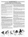
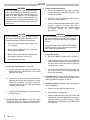
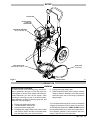

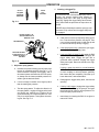
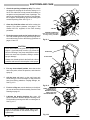


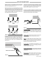

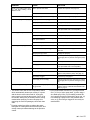


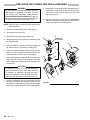
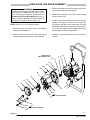
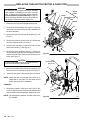


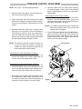
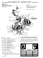
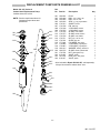
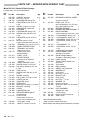
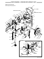

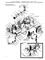
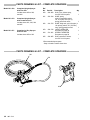
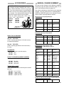


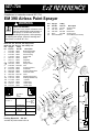
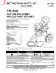

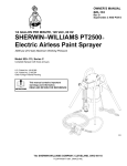
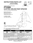


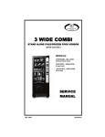
![[Product Monograph Template - Schedule D]](http://vs1.manualzilla.com/store/data/005793815_1-9ff4321a86e1483b72bfcf39a23d58ab-150x150.png)