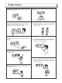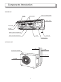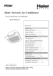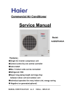
1
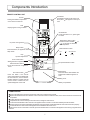
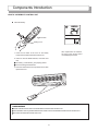
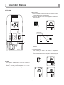
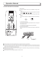
● Thank you for purchasing or distributing Hisense products.
● Please read this manual carefully before using the appliance.
● Please keep this manual in a safe place.
● Specifications may vary slightly to those indicated due to technical
improvements.
Contents
1. FEATURES
1
2. SAFETY NOTICE
2
3. COMPONENTS INTRODUCTION
5
4. OPERATION MANUAL
9
5. MAINTENANCE
15
6. WISE OPERATION
17
7. TROUBLE SHOOTING
18
8. TECHNICAL TABLES AND DIAGRAMS
21
APPENDIX: INSTALLATION
23
RZA-0-1000-908-SM-B
Features
Novel exterior
Excellent selected material, compact structure, arc
streamline, simple line, luxurious and elegant, novel
design, representing international prevalent trend.
Trouble shooting
When it has fault, the microcomputer can self-diagnose
and display the reason of the fault, convenient for
m
a
i
n
t
e
n
a
n
c
e
.
Microcomputer controlled operation
Internal microcomputer with powerful function, easy
operation and use of remote control unit, air
conditioner can automatically adjust the room
temperature and humidity without troubling you, give
you a pleasant enjoyment.
Ultra-mute operation
Excellent flue design, best angle for airflow intake and
outlet, enable the airflow to be quiet and smooth with
m i n i m u m
n o i s e .
Air freshing function
Multi-photocatalyst comprehensive functions, effetely
eliminate the soot, bacteria and peculiar smell in the
indoor are, provide you with a green and healthy space.
Night energy saving mode
This function can automatically change the room
temperature setting, providing you with comfortable
environment, saving energy.
Automatic adjustment of airflow speed and airflow
direction
The airflow of the indoor unit can be set to four modes
of AUTO/HIGH/LOW/MUTE, and the airflow from the air
conditioner can be blown to each corner of the room
through changing the angle of the flap vanes.
12 -Hour ON and OFF Timer
This Timer can be set to automatically turn the unit on
or off at any time within a 12-hour period.
1
Safety
!
!
Notice
WARNING: Operations displaying this symbol may result in fatal injury.
CAUTION: Operations displaying this symbol may result in serious injury.
A. Instructions for installation
B. Instructions for operation
Do not sit directly in the cold air stream from the
appliance, or set excessively low operation
temperature.
Installation only by authorized professionals
through local distributors.
Attention should be paid to power source, supply
capacity, electrical wire or sockets.
R
Never install the appliance in an area near
inflammable gas.
Connect the appliance, using a separate cable and
plug, to a dedicated socket with a capacity not less
than 16A.
Install a correctly rated circuit breaker.
Don't insert articles into the air inlet and keep
children away from the appliance.
The appliance must be earthed. Never earth the
appliance to a gas or water pipe, lighting rod or
phone wire.
Correctly install tubes to avoid water leakage.
Use the correctly rated electrical cable and protect
from damage or heat sources.
2
Safety
Notice
Avoid unnecessarily plugging and unplugging the
appliance.
Never operate the appliance with wet hand.
Keep plants or pets away from the air source.
Be sure that the power plug is clean and completely
inserted to the socket.
Do not clean the appliance by washing with water.
Hold the plug, not the wire, when unplugging the
appliance.
The appliance must only be used for room air
conditioning.
Do not let the appliance under heavy load.
3
Safety
Notice
Keep the room well ventilated, especially in rooms
where burners are used.
Do not place other electrical appliance under the air
conditioner.
Disconnect the appliance when cleaning. Unplug the
appliance when operation of the appliance stops.
Make sure that fan stops before cleaning.
Unplug the appliance in the event of abnormal
operation and contact a distributor or the after-sales
service for repair.
Keep gas burners away from moving air from the
appliance.
Only qualified professionals should move the
appliance for reinstallation. Contact the distributor or
after-sales service for assistance.
Unplug the appliance when operation is suspended
for long periods.
Only qualified professionals should repair the
appliance. Contact the distributor or after-sales
service for assistance.
Regularly check the securing bolts and support rack
of the outdoor unit.
4
Components
Introduction
INDOOR UNIT
Air filter
Air fresh filter
Indoor unit sensor(inside)
Switch button
Front cover
Air inlet
Impeller (up-down adjustment)
Air outlet
Impeller (left-right adjustment)
Power plug
Display panel
OUTDOOR UNIT
Cable
Tubes
Air inlet (rear and side)
Drainage hose
Air outlet
5
Components
Introduction
INDOOR UNIT DISPLAY PANEL
POWER
HI-POWER
TIMER
OPERATING
Each part stands for:
1. Power indicator illuminating means the appliance in operating condition.
2. Timer indicator illuminating means the appliance in timer or sleep condition.
3. Operating indicator illuminating means the compressor in work condition.
4. Hi-power indicator illuminating means the appliance in hi-power condition.
INDOOR UNIT SWITCH PANEL
Indoor unit switch panel is under the front cover, it can be
used while remote control unit is bad or losing.
ON/OFF
6
Components
Introduction
REMOTE CONTROL UNIT
Transmitter
Transmitting signals to the indoor unit,
the symbol
will appear on the top of
LCD.
Sensor
Testing the ambient temperature
of the remote control unit
LCD
Displaying the running condition.
T.SETTING
A
C
HOUR A
ON
Hi-power running button
ON/OFF
H.P.
Sleep button
Press the button, the appliance enter
sleep mode.
Flap
Up-down adjustment
Timer on/off button
Setting the time of appliance on/off.
Set/cancel timer button
Set or cancel the time of appliance
on/off.
A
OFF
TEMP.
On/Off button
Press the button to run, press again
to cease.
Temperature setting button
Press the button marked "
"or
"
" to increase or decrease
the temperature.
Mode selection button
SLEEP
Auto
Fan
cooling
MODE
FLAP
ON
dehumidification
OFF
FAN/MUTE
Fan speed selection button
SET
BATTERY
CLR
RESET
SENSOR
Reset button
Press the button after batteries are
loaded and indication appears on
LCD.
A/C sensor button
Press the button if the remote
control unit is liable to be affected by
the heat resource, such as electric
blanket, radiator or sunlight, this will
use the sensor of indoor unit, the
symbol will appear on the LCD.
Sliding cover
Battery compartment
COMMONSENSE
Remove the batteries in the remote control unit when it is not used for a long period.
Replace the batteries when the indication on the LCD of the remote control unit is faint, or the remote control unit cannot be set
or operated.
Properly dispose of used batteries.
Keep the remote control unit away from cold or hot air, sunlight or heat sources.
Contact the local distributor if the receiver in the appliance does not work in a room illuminated by fluorescent tubes.
Remote control unit must be used within its effective range or the timer and the temperature control will not function properly.
Control will fail if two of the same model appliances are installed in the same room.
If the remote control unit is fixed on the wall, press the On/Off button to ensure that the appliance is receiving a signal from the
device.
7
Components
Introduction
HOW TO USE REMOTE CONTROL UNIT
Install the battery
A
T.SETTING
C
2
RESET button
A
3
A
Sliding cover
1
1. Press the two sides of the cover of the battery
component and slide it downward and remove.
After replacement of batteries,
the LCD on the remote control
unit will display the status.
2. Insert two AAA #7 Alkali batteries, and make sure
that,
The anode (+) and cathode (-) are properly placed.
Do not use Manganese batteries.
3. Press the Reset button with a pointed tool and then
replace the cover.
COMMONSENSE
Please make the remote control unit transmitter aim at the receiver of indoor unit.
There shouldn't have any obstacle between the remote control unit transmitter and the receiver of indoor unit.
Don't throw and break the remote control unit.
8
Operation
Manual
PREPARATION BEFORE RUNNING
Raise the front cover, and then install the air filter.
MANUAL OPERATION (COOLING, DEHUMIDIFICATION, FAN)
Basic operation
1.Before running the appliance, press the "MODE" for selection
one mode of the dehumidification, cooling and fan.
2.Press the "ON/OFF" button to start the appliance.
3.Press the "TEMP." button to set the temperature you wish.
T.SETTING
C
2
ON/OFF
H.P.
TEMP.
3
COMMONSENSE
SLEEP
●A certain period of time is required to reach the desired
temperature since the air of room cycles all the time.
● When appliance works in cooling and dehumidification
MODE
FLAP
mode, if blocked by accumulated water drops, then air
1
ON
SET
BATTERY
OFF
filter should be cleaned and air fresh filter should be
FAN/MUTE
cleaned or replaced.
CLR
SENSOR
RESET
9
Operation
Manual
AUTO RUN
Basic operation
1. Press the "MODE" button for selection of the "AUTO" function
for automatic cessation of the appliance.
2. Press the "ON/OFF" button and the appliance is then set in
automatic mode.
ON/OFF
A
T.SETTING
C
T.SETTING
C
A
A
2
Illuminating
ON/OFF
H.P.
TEMP.
3
POWER
SLEEP
HI-POWER
TIMER
OPERATING
MODE
FLAP
1
ON
SET
BATTERY
OFF
FAN/MUTE
Press again the "ON/OFF" button to cease the operation of the
appliance.
CLR
SENSOR
RESET
3. Temperature Setting
Each press of the "TEMP." will result in a temperature
o
adjustment of 1 C.
A few seconds later, the room temperature will be displayed
on the LCD of remote control unit.
A
T.SETTING
C
NOTICE:
The appliance is designed to control the function of
A
operating mode automaticly, as well as airflow and air
A
direction, according to the temperature in the room
detected by the appliance or the setting. A time lapse of a
A
T.SETTING
A
C
few seconds will occur before alteration of airflow.
10
C
A
A
A
A
Operation
Manual
FAN SPEED AND DIRECTION ADJUSTMENT
Basic operation
When the appliance works, press "FAN/MUTE" change airflow
speed.
Press "FAN/MUTE" each time, indoor unit fan speed can be altered
among
A
,
,
,
.
When the appliance works, press "FLAP" change vertical airflow
direction.
T.SETTING
C
Press "FLAP" each time, fan impeller will appears the following in
turn:
FLAP
6
5
4
3
2 1
1. Vertical airflow adjustment
Fan auto mode: fan impeller sways between 6 and 3 in cooling and
ON/OFF
H.P.
TEMP.
dehumidification mode.
Fan sweep mode: fan impeller sways from top and bottom.
SLEEP
2.Horizontal airflow adjustment
Adjust horizontal airflow by pushing the left-right fan impeller with
hands.
MODE
FLAP
ON
SET
BATTERY
OFF
FAN/MUTE
CLR
SENSOR
RESET
Left-right airflow
fan impeller
When the appliance works in dehumidification mode, fan speed is low and can not be altered.
The remote control unit can be used to adjust the air direction. Manual adjustment may result in conflict between the actual
position and the desired position by the remote control unit. Turn off the appliance with the remote control unit and restart the
appliance after the fan imperller is completely closed.
Water drops may accumulate around the air inlet if the appliance is operated for cooling in humid seasons or for dehumidifying.
Adjust the fan imperller correctly.
Never attempt to touch the rotating fan impeller for whatever reason.
11
Operation
Manual
TIMER SWITCH ON/OFF
Postponed Start Setting
The appliance will start operating after the period set by the timer.
When the appliance is set in the "Cooling" mode, a desired temperature
will be reached after a desired set time (the reservation function).
T.SETTING
C
Postponed cessation setting
Set the time for cessation of the appliance, the appliance will then
stop operating upon expiry of the set period.
ON/OFF
H.P.
TEMP.
SLEEP
MODE
FLAP
ON
OFF
SET
BATTERY
FAN/MUTE
CLR
SENSOR
RESET
1. Press the "ON
/ OFF
"
button. Each press will alter the
hour indication by one.
Maximum number is 12.
A
C
For example: If you wish the
appliance start three hours
later.
The timer switch illuminates when the timer
is set.
T.SETTING
HOUR
ON
A
T.SETTING
C
For example: If you wish the
appliance stop one hour later.
illuminating
HOUR A
OFF
POWER
TIMER
HI-POWER
OPERATING
2. Press the "SET" button to confirm the time setting.
Press the "CLR" button to inactivate the time setting.
12
A
Operation
Manual
SLEEP SETTING MODE/HI-POWER OPERATION/AIR FRESHING
Sleep Setting Mode
This mode can be manually set to save energy while maintaining a
desired well conditioned atmosphere at night.
T.SETTING
C
Press the "SLEEP" button during dehumidifying and cooling.
T.SETTING
C
ON/OFF
H.P.
TEMP.
SLEEP
A
A
MODE
FLAP
ON
SET
BATTERY
OFF
Cancellation of "SLEEP"
Press the "SLEEP" button once.
FAN/MUTE
CLR
SENSOR
RESET
Air freshing
When appliance works, the air fresh filter of indoor
unit can effectively filter, absorb and decompose
harmful ingredient.
Hi-power operation
The appliance set in this mode will produce lower temperature air
than ordinary condition. This function can make you feel
comfortable rapidly in summer.
Press "H.P." button, the appliance start to work in this mode.
Press "H.P." button again, to cancel this mode.
EMERGENCY OPERATION
Open the front cover, the switch panel can be found.
Press the "ON/OFF" button to start the appliance, and in this condition the appliance will automatically select operating mode in
terms of indoor temperature.
Press the "ON/OFF" button again to cease the appliance.
NOTICE:
The operation can be only used while remote control unit is bad or losing. Moreover, don't often press the button.
13
Maintenance
!
CAUTION
Cuts and abrasions may result from contact with the sharp components inside the appliance.
Clean the air filter once very two weeks.
3. Cleaning the air filter
1. Cleaning of indoor unit
Wipe the indoor unit with a dry soft cloth damped
in 40℃ water.
Raise the front cover and take out the air filter.
2. Front cover cleaning
After cleaning the dirt of the air filter, please
wash the air filter by water then dry it.
In terms of the operation shown as picture,
unload the front cover.
2
1
Wipe and dry the front cover with a sponge or
similar substance.
Mild detergent can be used for excessive dirt.
Install the air filter and hold both sides of the
front cover as shown by the arrows.
In terms of the operation shown as picture, load
the front cover.
14
Maintenance
4. Cleaning and replacement of air fresh filter
Raise the front cover and take out the air filter.
5. Long-term cessation
Warm and air the inside to dry the appliance.
B efore unplug the appliance for cessation of
operation, press "ON/OFF" button to cease the
appliance, then pull out the power plug.
Take out the dirty air fresh filter from the air filter.
There are two kinds of air fresh filter, the
photocatalyst health filter can be used again after
washed by water and dried; the electrocstatic air
cleaning filter should be replaced with a new one.
Cl ean the air filter and take out the air fresh filter.
Install the air fresh filter onto the air filter and
close the front cover as shown by the arrows.
Remove the batteries from the remote control
unit.
15
Wise
Operation
Blockage of the air inlet or outlet may reduce the
cooling capacity of the appliance.
Excessively low temperature setting may be
harmful to health and will result in high power
consumption.
Cooling capacity can be reduced by
accumulated dirt on the air filter. Clean the air
filter when noise is heard or water drops
accumulate at the outlet.
Make sure windows and doors are properly
closed. Draft strips are recommended for use in
summer .
Window blind reduces 15% of sunlight and
window strips reduce 50%.
Adjust the wind direction to level for cooling.
Please use the timer reasonably to save
consumption.
Properly set the temperature.
When setting for cooling, the most desirable
difference between inside and outside
temperature is 5℃ . 1℃ increase of the set
temperature will save 10% of power
consumption.
16
Trouble
Shooting
Strange odor
Odors from wall carpet or clothing will be
absorbed and transmitted by the appliance.
Failure of airflow conversion
Airflow cannot be altered when the
dehumidification are started.
Sound of water flow
From circulating refrigerant inside.
Postponed operation
The safety function postpones 3 or 5 minutes
before operation after the appliance is
connected to the power supply.
Strange sound
Caused by shrinkage due to coldness.
Wait
a minute
Ka
17
da
Trouble
Shooting
Make sure any of the following circumstances occurs:
Failure of Operation
Failure of Desired Cooling Capacity
Sleep mode for energy-saving
Excessive people in the room
Power failure
Operation of the appliance will be recovered after
failure of power supply.
Door or window are not closed.
Power is disconnected
Low fan speed is set.
Short circuit or blown fuse
Temperature is set too high for cooling.
Signal from the remote control unit is out of reach
of the indoor unit receiver.
Batteries in the remote control unit are
exhausted or incorrectly inserted.
Air filter is blocked by dirt.
The button "RESET" is not pressed.
Excessive storage around the outdoor unit.
18
Trouble
Shooting
Contact the after-sales service for repair should any of the following events occur (see the Warranty Card).
Strange sound
Burned smell
Water leakage from indoor unit
Hot power plug
Blown fuse or circuit breaker trip
Loosed or corroded support rack
Additional Information
Unplug the appliance for any of the following:
After a long period of operation, the safety device
Long term cessation
starts, and sometimes the appliance cannot be
Lighting and thundering weather
operated.
Maintenance
Water drops may accumulate on the surface of the
Suspicious problem
appliance in a rainy screen or a long period of cooling
or dehumidification
The appliance must be used in a proper area as
Voltage abnormal protection
regulated.
Operation of the appliance will cease when
The air filter must be regularly cleaned to prevent
abnormal voltages are encountered.
water accumulation caused by dirt blockage.
Desired temperature may not be reached for
restriction of ambient temperature or blockage of the
air filter .
19
Technical Tables and Diagrams
O
1. PERMITTED AMBIENT TEMPERATURE FOR THE AIR CONDITIONER IS AS FOLLOWING: +18~+43 C(GB/T 7725-1996).
2. MAIN SPECIFICATIONS OF THE PRODUCT
Model
KF-5002GWE
Rated voltage
AC,
Voltage range
220V
Rated frequency
50Hz
Rated input power
cooling
Capacity
220V-230V
1.92kW
~
5.0kW
cooling
3
Circular airflow(high)
750m /h
3
Refrigerant/quantity
R22/1.85kg
Weight (indoor unit/outdoor unit)
13.0kg/54.0kg
。
8m/80
Max. Remote control distance/angle range
3. REFRIGERANT FLOW DIAGRAM
Indoor unit
Outdoor unit
Wide
service
valve
Compressor
Accumulator
Heat exchanger
Heat exchanger
Wide
tube
O.D.12.7
Narrow
tube
O.D.6.35
Narrow
service
tube
Caplillary
20
Filter
Cooling cycle
Technical Tables and Diagrams
4. ELECTRICAL WIRING DIAGRAM
INDOOR UNIT
YEL/GRN
EVAPORATOR
POWER SOCKET
YEL/GRN
BRN
SENSOR
POWER TRAN.
BLU
TERMINAL PANEL
0
BRN
CONECTION WITH
OUTDOOR UNIT
SENSOR
1
2
3
RED
4
BLU
5
BLK BLK BLK BLK
2 1
2 1
1
1
1
2
SEC
1
2
WHT
WHT
1
2
COM
CM
FLAP1
1
2
3
4
5
1
2
3
4
5
RED
ORG
YEL
PUR
BLU
STEP
MOTOR
FLAP2
1
2
3
4
5
1
2
3
4
5
RED
ORG
YEL
PUR
BLU
STEP
MOTOR
CONTROL BOARD
PRY
1
2
SU
ROOM
COIL
SW
1
1
1
2
FM
PULSE IN
71
71
~
~
31
3 1
3
3
5
5
BLU
RED
YEL
SWITCH PANEL
2
2
BRN
1
2
BLK
BRN
BRN
WHT
COIL
2
2
DISPLAY PANEL
FAN MOTOR
OUTDOOR UNIT
TERMINAL PANEL
CONECTION WITH
INDOOR UNIT
1
YEL/GRN
2
3
4
5
BLK
WHT
RED
GRY
CAPACITOR
PNK
WHT
CAPACITOR
BLK
WHT
R
BRN
C
S
FAN
MOTOR
COMPRESSOR
YEL/GRN
YEL/GRN
21
Appendix:
Installation
1. SUMMARY
1.1 Notice
This operation manual has explicit information for
installation and maintenance in most conditions. Contact
the local distributor or after-sales service for further
information.
1) Wiring notice
Only qualified professionals should carry out wiring of the
appliance.
Disconnect the power supply before completion of wiring,
piping or checking the appliance.
Voltages generated by the appliance is fatal.
Read the electrical schematic diagram and explanation
before installation. Improper installation and earth
connection may result in fatal injury.
C onnect the earth as required by local regulations.
Tightly fasten all the wiring connections to prevent
overheating or fire.
Special power, switches and sockets are required for the
power supply of the appliance.
Electric meter capacity must be larger than or equivalent to
16A.
Remark per EMC Directive 89/336/EEC
To prevent flicker impression during the start of the
compressor (Technical Process) and the adversely influence
caused by the 2nd harmonics of compressor following
installation conditions do apply
1. The power connection for the air conditioner has to be done
at the main power distribution. This distribution has to be of a
low impedance is reached at 32A fusing point.
2. No other equipment has to be connected to this power line.
3. For the detailed installation acceptance please refer to your
contract with the power supplier, if restrictions do apply for
products like washing machines, air conditioners or electrical
ovens.
4. For the details of the power of air conditioner, please refer to
the rating plate of the product.
5. For any question contact your local dealer.
2). Transport
C arefully move the outdoor unit.
3). Installation
----When the appliance is mounted to the ceiling or the wall,
Make sure that the ceiling or the wall is strong enough for the
appliance.
Make a wood or metal frame to support the appliance if
necessary.
----When the appliance is mounted in a room,
Properly insulate the outdoor unit, and make sure there is no
moisture on the appliance or on the floor.
----When the appliance is installed on a damp or uneven area,
Make a flat concrete base and place the base under the
outdoor unit.
----When the appliance is installed in an area of strong winds.
Using firm bolts and metal frames to fix the properly covered
outdoor unit.
----When the appliance (Model Heat Pump) is installed in an
area of heavy snow.
The outdoor unit must be installed in a position above the
snow accumulation.
4). Connection
Use the shortest tubes possible
Using a flaring method
Smear some refrigeration oil between the flared surface and the
connected tube.
Fasten the nuts with a torque wrench to prevent leakage of
refrigerant.
Check for leakage before trial operation.
5). Maintenance
Disconnect the power before checking the electrical
components and the circuits.
Avoid contact with the moving parts of the appliance.
Clea r the site and make sure there is no installation debris left in
the appliance.
6). Other
Keep the room well ventilated during installation.
1.2 Installing instruction
Read the operation manual before installation and keep this
manual in a safe place.
1)Tools
1. Screwdriver
2. Phillips head screwdriver
3. Knife or wire stripper
4. Steel ruler
5. Spirit level
6. Hammer
7. Percussion drill
8. Tube cutter
9. Pipe flarer
10. Pipe bender
11. Adjustable spanner
2) Attachment
(see the packing list)
3) Parts Package
Copper tubes, components and insulation materials for the
outdoor unit.
4) Type of the copper tube and insulation materials
1. Table 1 indicates that tubes should be cut with an additional
length of 30cm-40cm, to reduce the vibration from the outdoor unit.
ITEM
KF-5002GWE
Narrow tube
Outside Diameter
6.35mm
Wide tube
Thickness
0.8mm
Outside Diameter Thickness
12.7mm
0.8mm
2. The insulation materials for the copper tubes should conform to
the required length and the wall thickness should not be less than
8mm.
3. Insulated copper wires should be used for wiring and the
specification should depend on the length.
5) Additional materials for installation
1. white tape
2. nails or clips (as required)
3. putty
4. refrigeration oil
5. clips for fixing refrigerant tubes
22
Appendix:
Installation
2. INSTALLATION LOCATION
2.1 Indoor unit
!
2.2 Outdoor unit
Maintain the required space
The outdoor unit should be installed away from the following:
Heat source and fan exhausting (Figure 3);
Director sunlight;
WARNING around the appliance to
prevent overheat.
The location for installation of the appliance should not be in an
area with the following:
Di rect sunlight
H eat resource
Inflammable gas
Thick oil fog
The appliance should be installed in an area,
Where the inside space can be evenly conditioned, or
Which is strong enough for the appliance, or,
Having the shortest distance for the copper tubes and water
drain hose, and
Having desired space around the appliance for maintenance
and ventilation.(Figure 1)
8
Figure 3
The outdoor unit should be installed in an area with,
Cool temperature;
Good ventilation;
Desired space for air inlet, outlet and maintenance
(Figure 4)
Min. 5cm
Min. 5cm
Min. 5cm
Top obstacle
Figure 1
15
H
Added Refrigerant
(g/m)
7
Valve side
Min. 25cm
Provided Tube(M)
20
Min. 10cm
Air outlet
2m 2m Obstacle
L
Min. 10cm
Air outlet
Air inlet
Tube arrangement
Min. 40cm
4
L: Maximum length of the tube connecting the indoor unit and the
outdoor unit.
H: The height difference between the indoor unit and the outdoor
unit.
Figure 4
Ground
Min.10cm
Air inlet
2
Strong base (10x10cm concrete or alike). The appliance
should be placed not less than 10cm high (Figure 5).
Tube length(L)
Indoor unit
Firm bolts(4)
Height difference(H)
Outdoor
unit
Air inlet
Min. 10cm
Concrete or alike
Figure 2
Ab
* If the length of the tube is exceed 7m, an additional 20g/m of
refrigerant should be added per 1m.
!
WARNING
ou
t4
0c
Abou
t 10c
m
m
Fix the base with firm bolts to reduce vibration and noise.
The indoor unit should not be
installed below a height of 1.8m.
23
Appendix:
Installation
3. INSTALLATION OF INDOOR UNIT
3.1 Take off the back cover
1) Release the clips as shown by the mark " " on the back
cover.
2) Take off the back cover.
2) Unload the bottom cover of indoor unit with flat screw
driver, and according to direction of lining tube, leave the
cutting part of left bottom or right bottom cover with
saw.(figure 10)
3.2Drilling
1) Locate the back cover of the indoor unit on the wall, and
determine the desired place with a spirit level and a ruler.
Before drilling, do not fix the back cover onto the wall.
2) According to direction of the tube ,drilling for tubes according
to the location of the appliance. It is recommended that the
rear right be used for wiring and drilling.
3) Drill a 65mm hole in the wall (Figure 6), make sure the hole is
inclining to the outside .
Indoor
Cutting part
Figure 10
Outdoor
3) Bind the electrical cable drainage hose, refrigerant tube, air
exchange tube together tightly with white adhesive tape;
the electrical cable, refrigerant tube and the electrical cable
are fixed on the back of indoor unit with wedged slab, bend
the refrigeration tube and make the electrical cable and the
air exchange tube through hole of the wall smoothly(figure
11).
Figure 6
!
CAUTION
Before drilling, make sure that
there is no electric cable or pipe
in the area of the wall where the
hole is to be drilled.
Lining cover
3.3 Installation of the back cover
1) check with a spirit level that the back cover is installed
horizontally. (Figure 7)
Back cover
Refrigerant tube
Electrical cable
Figure 7
Air exchange
tube
Figure 11
2) fix the back cover to the wall with the screws provided. (Figure
8). Make sure that the back cover is firmly fixed to he wall.
4) Install the dismantled bottom cover to indoor unit(figure 12).
Figure 8
B
3.4 Install the indoor unit
1) Thread the cable through the hole in the wall, an additional
13cm of slack power cable should remain inside the room.
(Figure 9)
A
C
Figure 12
5) Adjust the position of the indoor unit, fixing it firmly onto the
back cover(figure 13).
Back cover
Lining cover
Electrical cable
13cm
Figure 9
Figure 13
24
Appendix:
Installation
3.6 Wiring connection of the indoor unit
3.5 Wiring
(1)Before wiring, make sure the rated voltage indicated on the
1) Hold pull and open the front cover.
nameplate conforms to the local power voltage.
2) Release the screws and open the wire distribution cover
(2)Wiring should be carried out in accordance with the
(Figure 15).
instructions on the electrical schematic diagram (Figure 14).
Terminal
Panel of
the indoor
unit
Terminal
Panel of
the outdoor
unit
1
1
Wiring distribution
cover
Figure 15
2
2
3
3
3) Connecting cable should be placed along the back of the
indoor unit to the front for connection.
4)Connect the wire distribution terminals and corresponding
terminals .(Figure 16)
Figure 14
!
WARNING
Wi ring for connection of the indoor unit and the outdoor unit
should be conducted in accordance with local regulations.
Wiring connections must be fitted firmly.
The electrical wires should not be in contact with any of the
refrigeration tubes, compressor or other moving parts or
components.
The appliance must be connected to a good earth.
Figure 16
5) Check the connections and then fasten the distribution
cover and replace the front cover finally.
4. INSTALLATION OF THE OUTDOOR UNIT
Properly locate the outdoor unit as described by the Section 2.
If the outdoor unit is to be mounted on the wall ,make sure that
the wall and the support are strong enough for the appliance.
Wiring Connection
1) Release the fixing screws and take off the side cover.
2) Connect the terminals on the heap pump as required in the
Figure 14 and the Figure 17:
3) Always save an extra 10cm length of the electrical cable:
4) Earth the appliance according to related regulations of
electrical engineering:
5) Fix the connected terminals with clips and replace the side
cover if the connection is assured according to the wiring
diagram:
Wiring distribution
cover
Figure 17
25
Appendix:
Installation
5.REFRIGERANT TUBE
5.1 Flaring the tube
(1) Cut the tube with a tube cutter to the desired length
(30.50cm is recommended)
(2) Smooth the edge of the copper tube with a reamer or a file.
Hold the pipe vertically with one end downward to make
sure that no copper scraps fall into the copper tube.
5.3 Heat insulation of the refrigerant tube
All refrigerant tubes must be insulated heat with at least 8mm
thick insulation materials. (Figure 22)
Heat insulation materials
Thickness
of 8mm
Min. 8mm
Copper
tube
After
Before
Figure 22
5.4 Wrapping the tubes
(1) Tie the two refrigeration tubes (including electrical wire if
permitted as regulated), water drainage hose with white
tape.
(2) Wrap half of the tubes outside the room starting from the
end. (Figure 23)
Reamer
Figure 18a
Figure 18b
(3) Put the tube flarer on the copper tube.
(4) Flare the copper tube ( Figure 19)
Clip
Tapered nuts
Copper tube
Covering tubes with
heat insulation materials
Flarer
Figure 19
Figure 23
Note: The flared tube should have:
Smo oth internal surface
Smooth edges
C onsistent length of the tapered surface
5.2 Connection of the tubes
(1) The sealing tube must be used to prevent dust or water
from getting into the tube.
(2) Before connecting the tube, apply some refrigerant oil on
the surface of the flared tube and connections to prevent
air leakage.( Figure 20)
(3) Align the connecting tube and the flared tube, and then
turn the tapered nut to connect tightly. (Figure 21)
Application
of refrigerant oil
Connecting
tube
(3) Fix the wrapped tubes on the wall in clips with a space of
120cm.
Note: Do not tie the tubes too tight as this may reduce heat
insulation. Separate water drainage hose and refrigeration
tubes to prevent formation of water droplets.
5.5 Ending of installation
After completion of wrapping and insulation, seal the hole on
the wall with a suitable sealant.
5.6 Discharge gas
Place appliance A and then B. Air purging method is as
follows:
(1) Turn down the nuts on the wide and narrow tubes.
(2) Loose the nut of the flared wide tube one complete turn
with a spanner.
(3) Turn counterclockwise to open the core of the valve with a
socket screw wrench. Some gas will come out from under
the nut of the flared end of the wide tube. Tighten the nut
10 to 15 seconds later.
(4) Test for leakage at the tube connector with soapy water or
a meter. If there is no leakage, turn counterclockwise to
open the tube core of the valve on the wide tube with a
socket screw wrench.
(5) Tighten the nuts on the wide , narrow tube valves and the
valve cover.
Flared tube
Figure 21
(4) Fasten the nuts with a spanner.
Please contact the technical service for further information.
26