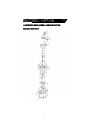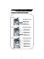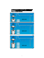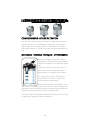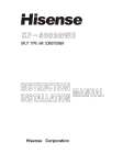
1
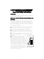
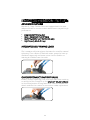
STAGE
REACTION 4
CANISTER FILTER
U.V.
STERILIZER
TRANSWORLD AQUATIC ENTERPRISES INC.
TABLE OF CONTENTS
Important Safety Instructions
3—5
Reaction Parts—Exploded Views
6—9
Introduction
10-12
Getting Started
13-16
Maintenance Procedures
17-21
Specifications
22
Notes
23
2
WARNING
To guard against injury, basic safety precautions should be observed, including the following:
READ ALL SAFETY INSTRUCTIONS BEFORE USE.
DANGER
To avoid possible electric shock, special care should be taken
since water is employed in the use of aquarium equipment. For
each of the following situations, do not attempt to repair yourself: return the appliance to an authorized service facility for service or discard the appliance.
A. If the appliance falls into water, DON’T reach for it! First unplug it and then retrieve it. If the electrical components of the
appliance get wet, unplug the appliance immediately.
B. Carefully examine the appliance after installation. It should
not be plugged in if there is water on parts not intended to be
wet.
C. Do not operate any appliance if it has a damaged cord or
plug, or if it is malfunctioning or if it is dropped or damaged in
any manner.
D. To avoid the possibility of the appliance
plug or receptacle getting wet, position
aquarium stand and tank to one side of a wall
mounted receptacle to prevent water from
dripping onto the receptacle or plug. A “drip
loop”, shown in the Figure at the right should
be arranged by the user for each cord connecting an aquarium appliance to a receptacle. The ”drip loop” is that part of the cord below the level of the receptacle or the connector if an extension cord is used, to prevent
water travel along the cord and coming in contact with the receptacle. (Continued on pg 4)
3
D. (Continued from pg 3)
If the plug or the receptacle do get wet, DON’T unplug the
cord. Disconnect the fuse to the circuit breaker that supplies
power to the appliance. Then unplug and examine for the presence of water in the receptacle.
E. Close supervision is necessary when any appliance is used by
or near children.
F. To avoid injury, do not contact moving parts or hot parts
such as heaters, reflectors, lamp bulbs, and etc.
G. Always unplug an appliance from the outlet when not in
use, before putting on or taking off parts, and before cleaning.
Never yank the cord to pull plug from the outlet. Grasp the plug
and pull to disconnect
H. Do not use an appliance for other than intended use. The
use of attachments not recommended or sold by the appliance
manufacturer may cause an unsafe condition.
I. Do not install or store the appliance where it will be exposed
to the weather or to temperatures below freezing.
J. Make sure an appliance mounted on a tank is securely installed before operating it.
K. Read and observe all the important notices on the appliance.
L. This Appliance has a polarized plug (one blade is wider than
the other). As a safety feature, this plug will fit in a polarized outlet only one way. If the plug does not fit fully in the outlet, reverse the plug. If it still does not fit, contact a qualified electrician.
Never use with an extension cord unless plug can be fully inserted. Do not attempt to defeat this safety feature.
M. This appliance is intended FOR HOUSEHOLD USE ONLY.
Do not use or mount this appliance in such a way that the top
vents are restricted or blocked. These vents are necessary to
avoid over-heating and insure safe operating temperature.
4
O. Make sure that all hose connections are firmly secured be-
fore turning on this filter. Never look directly at the UV lamp,
which may cause discomfort to eyes and skin.
Always turn the switch for the UV off and unplug entire canister
filter before performing any maintenance.
CLEANING
It is important to keep this appliance clean. Always unplug
the appliance before performing maintenance or cleaning of
the exterior of this hood. Wipe exposed surfaces carefully
with a damp terrycloth to remove any dust or mineral deposits which may collect over time. Make sure all surfaces are dry
before re-plugging into an electrical outlet. To prevent
scratching the appliance, use a damp terrycloth when cleaning.
SERVICING
In order to assure proper electrical connections and polarity,
replacement parts and servicing should be performed only by a
qualified electrician.
OPERATION
Please carefully read the entire “Owner’s Manual” for proper
operation procedures before proceeding with turning on this
appliance and adding livestock such as fish, corals, and invertebrates.
SAVE THESE INSTRUCTIONS
5
PARTS EXPLODED VIEW & IDENTIFICATION
Reaction Canisters
6
Reaction Canister 4-Stage Filter
PART
#
EFU- 1
Name
Female Hose Cap
PART
#
EFU- 26
Name
Capacitor
EFU- 2
Male Hose—Threaded
EFU- 27
Pump Motor
EFU- 3
Quick Disconnect Valve
EFU- 28
Main Power Supply
EFU- 4
Inlet Pipe
EFU- 29
Converter
EFU- 5
O-ring
EFU- 30
Underside Frame Cover
EFU- 6
Water Shut Off Lever
EFU- 31
Cover Handle Clamp
EFU- 7
Water Shut off Valve
EFU- 32
Priming LeverCompartment
EFU- 8
Sealer
EFU- 33
Priming Lever—Cover
EFU- 9
Filter Inlet Valve
EFU- 10
O-ring
EFU- 35
EFU- 11
Integrated Self - Priming Lever
EFU- 36
O-ring
EFU- 12
EFU- 13
Filter Cover
Hinge for UV Cover
EFU- 37
Impeller Ceramic Shaft
EFU- 38
Impeller Magnet
EFU- 14
UV Cover
EFU- 39
Impeller Fan Blades
EFU- 15
UV ON/OFF Switch
EFU- 40
Impeller Housing Cover
EFU- 16
UV Ballast
EFU- 41
Impeller Housing O-ring
EFU- 17 Male/female UV ConnectorPlug
EFU- 42
Impeller Housing Cap
EFU- 18
UV Compression Fitting Cap
EFU- 43
Imperller Cap Tab
EFU- 19
UV Compression Fitting
EFU- 44
Return Elbow
EFU- 20
UV Lamp—socket
EFU- 45
UV Exterior Housing
EFU- 21
UV Lamp
EFU- 46
Filter Basket Handle
EFU- 22
UV O-ring
EFU- 47
Filter Basket
EFU- 23
UV Compression Pipe
EFU- 48
Return Gasket
EFU- 24
Quartz Sleeve
EFU- 49
O-Ring
EFU- 25
Transformer
EFU- 50
Filter Body Hinge
EFU- 51
Filter Body Clamp
EFU- 52
Filter Body Handle Clamp
EFU- 34 Priming Lever—Suction Cup
7
Impeller cap
EFU- 53
Filter Body
EFU- 54
EFU- 55
Filter Body Support Base
Rubber Feet
REACTION 4-STAGE FILTRATION DESIGN
EFU-25
Filter Media Set Up
Basket 1
1) Layer white fine Filter Floss
2) Activated Carbon - 500g
.
Basket 2
1) Ceramic Rings - 500g.
2) Layer white fine Filter
. Floss
Filter Media Set Up
EFU-35
Basket 1
1) Layer black coarse sponge.
2) Layer white fine Filter
. Floss
Basket 2
1) Activated carbon - 500g.
2) Layer white fine Filter
. Floss
Basket 3
1) Ceramic Rings - 500g.
2) Layer white fine Filter
. Floss
Filter Media Set Up
EFU-45
Basket 1
1) Layer black coarse sponge
Basket 2
1) Layer white fine Filter
. Floss
Basket 3
1) Activated carbon - 500g.
2) Layer white fine Filter
. Floss
Basket 4
1) Ceramic Rings - 500g.
2) Layer white fine Filter
. Floss
8
What’s Included in the Box
EFU-25
EFU-35
EFU-45
9
COMPREHENSIVE 4-STAGE FILTRATION
Thank you for purchasing the Reaction 4-Stage high capacity
filtration system. This revolutionary canister filter incorporates
high media storing capacity with an innovative UV sterilizer
that polishes water to crystal clarity while keeping pathogens at
bay.
Mechanical - Chemical - Biological - UV Sterilization
Reaction 4-Stage Canister filters utilize
mechanical, chemical, biological filtration,
and UV sterilization for a balanced aquarium.
Water first enters the canister via the intake strainer and is guided through a
large sponge to trap particulate matter.
The water then reaches 500g of activated carbon to remove harmful dissolved organic compounds.
Water is directed over the ceramic rings
that offers a tremendous amount of surface area internally and
externally to grow beneficial aerobic bacteria that breaks down
harmful ammonia and nitrite to less harmful nitrate.
All filtered water then passes through our powerful UV-C lamp
for pathogen and green water elimination.
10
ADVANCED FEATURES
Reaction 4 - Stage Canister Filters are equipped with the most
advanced features to make routine maintenance easy with high
performance.
•
•
•
•
Integrated Self-Priming Lever
Quick - Disconnect Shut-Off Valve
On/Off Switch for UV-C Germicidal Lamp
High Capacity Media Storage
INTEGRATED SELF-PRIMING LEVER
Our innovative self-priming lever eliminates the need for manual
siphoning. Once canister is filled with water, pump the lever up
and down vigorously until water enters the inlet and the remaining air bubbles leave the outlet.
QUICK-DISCONNECT SHUT-OFF VALVE
Instantly creates a watertight seal that stops water from entering
or exiting the filter. Simply lift up the SHUT-OFF VALVE HANDLE
to the vertical position to stop water flow. Grab the handle and
detach and take the canister for convenient media replacement.
11
ON/OFF SWITCH FOR UV-C GERMICIDAL LAMP
This new revolutionary concept integrates a special UV-C lamp
to destroy green water and polish water to crystal clarity. The
convenient ON/OFF switch allows for complete user control.
NOTE: The UV-C switch should be turned off during the cycling
period to encourage the population of beneficial bacteria.
Never look directly at an exposed UV-C lamp as it may cause
irritation to eyes and skin.
HIGH CAPACITY MEDIA STORAGE
The new trend in canister filters is to increase the filter storing
capacity for larger amounts of chemical and biological medias.
This allows for higher water quality due to more media contact
through the initial pass. All filter baskets have convenient handles for removing and loading up all types of medias that can
be easily customized.
Reaction Canister filters
come installed with all necessary media right out of
the box for quick and easy
start-up
12
UNPACKING THE BOX
Carefully unpack your new Reaction Canister Filter and verify
that you have all the parts below.
NOTE: Picture below represents model EFU-25 with (2) media
baskets. Please refer to page 8 & 9 for models EFU-35 & EFU-45.
CHOOSING A LOCATION
Reaction Canister are gravity-fed filter systems. They must be
placed below the water level in order to function properly.
Attach INLET J-TUBE (10) to STRAINER/PREFILTER (11) and
hang inside of aquarium.
• Attach RETURN U-TUBE (5) to CONNECTOR (7) and ELBOW CONNECTOR (6) and RETURN NOZZLE (12) and
hang inside of aquarium.
NOTE: Spray Bar can be attached instead of Return Nozzle as
another return option.
• Insert the INLET J-TUBE (10) and RETURN U-TUBE (5) into
the two pre-cut HOSES (15). Align the other open ends of
the hose to the INLET/OUTLET VALVE (1) and cut hoses if
necessary so there are no kinks or bends.
• Once cutting of the hoses are completed, , measure the distance from the tank to the canister to ensure the hoses are
the right length.
•
13
REMOVING THE COVER
STEP 1 : Unsnap the two
handle clamps outward
and up.
STEP 2: Unsnap the remaining 2 handle clamps outward.
STEP 3: Continue to pull
outward and up until
cover detaches from filter
body.
14
PREPARING THE MEDIA BASKETS
Your filter is factory installed
with the correct sponges, carbon, and ceramic rings to
show proper placement.
It is necessary to remove the
baskets and rinse the activated
carbon bag under the sink for
30 seconds or until the water
runs clear before starting the
filter.
FILLING THE CANISTER FILTER
Once the activated carbon bag has been rinsed, place back into
the filter basket and fill up with aquarium water to 95% of the
capacity of the filter.
Clamp on the cover back to the filter body by repeating the
steps in opposite order.
Always check to ensure you have an air-tight seal and that each
handle clamp is locked in place before turning on the filter.
Note: The QUICK-DISCONNECT VALVE
handle must be in the horizontal position
in order to lock properly.
TURNING ON THE FILTER
Plug the receptacle of the filter into a
grounded 110V outlet. At this time you
should be able to hear the motor running.
Pump the Integrated Priming Lever up and
down vigorously until the air inside the canister filter escapes
out the return hose. Once the filter is running, return the lever
to the down position.
15
ADJUSTING THE WATER FLOW
Reaction Canister Filter’s unique QUICK DISCONNECT-VALVE
offers the option to regulate water flow for your aquarium.
While the filter is running you can slowly raise the handle to reduce the flow rate.
NOTE: It is very important NOT to raise the handle more than
halfway. Raising more than halfway may stop the flow of water
and cause malfunction to the motor and associated parts.
ADJUSTING THE WATER RETURN
Adjust the height or angle of the return hose back into your
aquarium to your specific needs.
If you have chosen to use the RETURN NOZZLE, you can turn
the nozzle to face upwards for more surface tension or downwards for more movement at the bottom of the aquarium.
If you have chosen to use the SPRAY BAR, adjust it so the small
openings in the spray bar are angled at a 45 degrees angle so it
breaks the surface of the water for more gas exchange.
WATER CHANGES
Regular maintenance is the key to a successful thriving aquarium. Maintaining an aquarium can be very easy with a regular
cleaning schedule.
Water changes should be carried out on monthly to bi-monthly
schedule depending on how much bio-load is kept.
25% water changes with gravel vacuuming is essential to keep
dissolved organic carbons to a minimum.
16
ROUTINE MAINTENANCE
Periodic filter media replacement is crucial for the well being of
your livestock. As most mechanical and chemical medias are
exhausted, they slowly lose performance and no longer filter
the water efficiently.
We recommend changing the media located inside the baskets
on a monthly basis.
MAINTENANCE PREPARATIONS
Close the QUICK DISCONNECT VALVE by lifting up on the handle. The handle should be in the vertical position to stop the
flow of water in and out of the filter.
Unplug the filter power cord.
Lift up on the handle of the QUICK DISCONNECT VALVE
and disconnect from the filter body. The water inside the hose
tubes will not leak.
Lift the Reaction Canister Filter from the main body and not the
cover to a sink or drain to perform cleaning and maintenance
husbandry.
Unlock the HANDLE CLAMPS and remove cover carefully.
Drain as much water out of the filter and remove baskets individually.
17
REPLACING THE FINE WHITE FILTER FLOSS
A. White Filter Floss should be changed on a monthly basis to
remove small trapped debris and free floating particulate
matter.
REPLACING THE COARSE BLACK SPONGE
A. Black Coarse Sponge should be changed on a monthly basis to remove medium to large trapped debris and free floating particulate matter.
REPLACING THE ACTIVATED CARBON BAG
A. Activated Carbon adsorbs dissolved pollutants and removes
the yellow discoloration of water and associated odors.
B. Replace Activated Carbon Bag on a monthly basis.
CLEANING THE CERAMIC RINGS
A. The Ceramic Rings are the primary biological support for
keeping toxic ammonia and nitrite at acceptable levels. Generally, the biological media should not be replaced unless detritus
and waste is prohibiting the amount of exposed surface area
available for the beneficial bacteria. Clean ceramic rings with
the aquarium water and NEVER use tap water that can destroy
the bacteria.
B. Replace Ceramic Rings as needed or add extra for higher volume aquariums with large bio-loads.
18
CLEANING/REPLACING IMPELLER
STEP: 1
Remove cover off filter and place
upside down.
You will need a flat head screwdriver.
STEP 2:
Wedge the flat head screwdriver
under the impeller cap tab and lift
up.
STEP 3:
Remove impeller cap tab.
STEP 4:
Disconnect the return elbow from
the UV housing by pulling in a
counter clockwise motion.
STEP 5:
Pull out impeller for cleaning or
replacement. It may be necessary
to also clean out the impeller
housing with a cotton swab for
slime and detritus accumulation.
19
REPLACING UV-C LAMP
The UV-C lamp within the Reaction Canister Filter requires replacement after 9-12 months use. Always disconnect the power
supply and NEVER look directly at the lamp.
Tools Required: Phillips Screwdriver, scissors, pliers
STEP 1:
Unscrew the (6) Phillips screws
from the underside of the cover.
STEP 2:
Unscrew the (2) Phillips screws
from the topside of the cover.
STEP 3:
Pull off the Suction Cup from the
underside of the Priming Lever.
STEP 4:
Unscrew the nut off the Priming
Lever and Pull out the Lever from
the top of cover.
20
REPLACING UV-C LAMP (continued)
STEP: 5
Picture of screw and Priming
Lever.
STEP 6:
Pull apart the internal black plastic
frame from the top frame.
STEP 7:
Cut the clear zip tie with your scissors to allow more slack to remove the UV-C lamp. The wires
should be re-attached with wire
or another zip tie for organization.
STEP 8:
Disconnect the male/female plug
that is connected to the UV-C
lamp.
STEP 9:
Loosen the compression fitting
with pliers and unscrew by hand.
Unsnap UV-C lamp from the
lamp holder and replace.
21
Rated
Canister
Media
Diameter
Capacity
Inlet
Hose
Size
Outlet
Hose
Watts/
Size Watts UV
Item #
GPH
Gallons
Filter
Height
EF-10
159 25 gal
13.93
8.17x8.17 1.92liters 5/8" 5/8" 11
N/A
EF-15
185 50 gal
15.91
8.17x8.17 2.88liters 5/8" 5/8" 13
N/A
EF-20
211 75 gal
17.87
8.17x8.17 3.84liters 5/8" 5/8" 15
N/A
EFU-25
198
100
gal
15.24
11.41 X
11.41
4 liters
5
5/8" 5/8" 23 Watt
EFU-35
250
150
gal
17.52
11.41 X
11.41
6 liters
6
5/8" 5/8" 27 Watt
EFU-45
290
175
gal
19.8
11.41 X
11.41
8 liters
7
5/8" 5/8" 32 Watt
22
Customer Service Information
For additional information or technical assistance
please call us at (310) 672-4099, M-F from 9AM-5PM
(Pacific Standard Time).
23
Transworld Aquatic Ent., Inc
3730 West Century Blvd, Suite 3
Inglewood CA 90303
Phone: 310-672-0480
Fax: 310-672-7261
E-mail: [email protected]
24