1
®
@
J
ModelNo.HRTL61706.1
SedalNo.
'S
SerialNumberDecal
Asa manufacturer,wearecommittedto providingcomplete
customersatisfaction.If you
havequestions,or if partsare
damagedor missing,PLEASE
CONTACT
OURCUSTOMER
SERVICEDEPARTMENT
DIRECTLY.
CALLTOLL-FREE:
Mon.=Fd.,6 a.m.=6p.m.MST
ONTHEWEB:
www.healthriderservice.com
CAUTION
Read all precautions and instructions in this manual before using
this equipment. Save this manual
for future reference.
www°healthrider°com
new products, prizes,
fitness tips, and much more!
TABLE OF CONTENTS
iMPORTANT
PRECAUTIONS
................................................................
3
BEFORE YOU BEGIN ......................................................................
ASSEMBLY ...............................................................................
OPERATION AND ADJUSTMENT ............................................................
HOW TO FOLD AND MOVE THE TREADMHLL ..................................................
5
6
12
20
TROUBLESHOOTHNG .....................................................................
CONDiTiONiNG GUiDELiNES ...............................................................
PART LiST ..............................................................................
22
24
26
ORDERING REPLACEMENT PARTS .........................................................
EXPLODED DRAWHNG ....................................................................
LHMHTEDWARRANTY ..............................................................
HeaHthRider is a registered trademark of HCON HP,Hnc,
2
27
28
Back Cover
iMPORTANT PRECAUTIONS
WAR NmNG:Toreduce
the.s. ofburns,
f re,e ectde
shoe.,
orinjury
topersons,
read
the
following
important
precautions
and information
before operating
it is the responsibility
of the owner to ensure
that all users of 1his treadmill are adequately
informed of aH warnings and precautions.
2,
Use the treadmill
only as described.
3. Place the treadmill on a level surface, with at
least eight feet of clearance behind it and two
feet on each side. Do not place the treadmill
on any surface that blocks air openings. To
protect the floor or carpet from damage, place
a mat under the treadmill,
4. Keep the treadmill indoors, away from moisture and dust. Do not put the treadmill in a
garage or covered patio, or near water.
5. Do not operate the treadmill where aerosol
products are used or where oxygen is being
administered,
6. Keep children under the age of 12 and pets
away from the treadmill at all times.
7. The treadmill shouH be used onny by persons
weighing 300 pounds or less.
8. Never allow more than one person on the
treadmill at a time.
9. Wear appropriate exercise clothes when
using the treadmill. Do not wear loose cJothes
that couJd become caught in the treadmill.
AtHetic support clothes are recommended for
both men and women. A/ways wea/'athletie
shoes. Never use the treadmill
withbare feet,
wearing only atockinqa,or in sandals.
18. When connecting the power cord (see page
12), plug the power cord into a surge suppressor (not ineJuded) and pJug the surge
suppressor into a grounded circuit capable of
carrying 15 or more amps. No other appliance
should be on the same circuit. Do not use an
extension cord.
the treadmill.
11. Use only a single-outJet surge suppressor
that meets aH of the specifications
described
on page 12. To purchase a surge suppressor_
see your IocaJ HealthRider dealer or call the
toll-free telephone number on the front cover
of this manual and order part number 146148,
or see your total electronics store.
12. Failure to use a properJy functioning surge
suppressor could resuJt in damage to the controi system of the treadmill, if the control syso
tern is damaged, the walking beJt may change
speed, accelerate, or stop une×pectedJy,
which may result in a fall and serious injury.
13. Keep the power cord and the surge suppressor away from heated surfaces.
14. Never move the waJking belt while the power
is turned off. Do not operate the treadmill if
the power cord or plug is damaged, or if the
treadmill is not working properly. (See TROUBLESHOOTmNG on page 22 if the treadmill is
not working properly.)
15. Read, understand, and test the emergency
stop procedure before using the treadmill (see
HOW TO TURN ON THE POWER on page 14).
18. Never start the treadmill while you are standing on the walking bent. Always hoJd the
handrails while using the treadmill
17. The treadmill is capabJe of high speeds.
Adjust the speed in small increments to avoid
sudden jumps in speed.
18. The pulse sensor is not a medical device.
Various factors, including the user's movement, may affect the accuracy of heart rate
readings. The puJse sensor is intended only
as an exercise aid in determining
heart rate
trends in general
.....
19.Neverleavethe treadmillunattendedwhileit
23.Inspect
and properly
treadmHJ regularly.
is running. Always remove the key, unplug
the power cord, and switch the reset/off cir=
cuit breaker to the off position when the
treadmill is not in use. (See the drawing on
page 5 for the location of the circuit breaker.)
tighten all parts of the
24.DANGER: Always
unplug
thepower
cord immediately after use, before cleaning the
treadmill and before performing the maintenance and adjustment procedures described in
this manual Never remove the motor hood un-
20. Do not attempt to raise, lower, or move the
treadmill until it is properly assembled. (See
ASSEMBLY on page 6, and HOW TO FOLD
AND MOVE THE TREADMILL on page 20.)
You must be able to safeJy tilt 45 pounds (20
kg} to raise, lower, or move the treadmill
less instructed to do so by an authorized sero
vice representative. Servicing other than the
procedures in this manual should be performed
by an authorized service representative only.
25. This treadmill
is intended
for in-home use
only. Do not use this treadmill in a commercial rental or institutionaJ setting.
21, When folding or moving the treadmill, make
sure that the storage latch is fully dosed.
22. Never insert any object into any opening on
the treadmill.
WARNING: Before
beginning
th sora,yexercise
program,
consult
yo,rphysician.
Th s
is especially important for persons over the age of 35 or persons with pre-existing health problems.
Read aH instructions before using, mCONassumes no responsibility
for personal injury or property
damage sustained by or through the use of this product.
SAVE THESE iNSTRUCTiONS
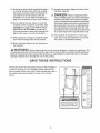
The decaJs shown here have been placed on the treadmill, if
a decal is missing, or if it is illegible, call the toll-free telephone number on the front cover of this manuaJ and order a
free replacement decal Apply the decaJ in the tocation
shown.
_fotect yourself and
_thers f_om risk of serious
_Stand_nly _n_he
_tar_J_0_ _t0ppin_
treadmill
m
-¢h_Lng_
Sp_d in
,H01d_an_,ail_t_
_f_ty _lJ__hJl_
_er_J_g treadmill¸
Fullyen_ag__t_ra_
I_e_t I_v_l _r_r_
fcl_Jn_tre_mJllint_
4
_
_h_l_r_n_n o_
_Y
"_no_k
........
BEFORE YOU BEGIN
Thank you for sebcting the revoUutionary HeaUthRide¢_
PRO H450i treadmill The PRO H450i treadmHUoffers
an impressive array of features designed to make your
workouts at home more enjoyabb and effective, And
when you're not exercising, the unique PRO H450i
treadmHUcan be foUded up, requiring bss than haft the
floor space of other treadmHUs,
ing this manuaU, phase see the front cover of this manuaL To heUpus assist you, phase note the product
modeU number and seriaU number before contacting us,
The modeU number of the treadmill is HRTL61706,1,
The serial number can be found on a decal attached to
the treadmill (see the front cover of this manual for the
location),
For your benefit, read this manua! carefully before
using the treadmill, ff you have questions after read-
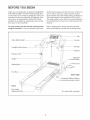
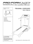
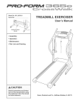
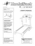
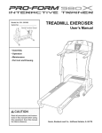
Before reading further, please review the drawing
below and familiarize yourself with the labeled parts,
Fan
Water Bottle Holder*
Console
Handgrip Pulse Sensor
Key/Clip
Handrail
Storage Latch
Upright
Reset/Off
Breaker
Walking Belt
Foot Rail
RIGHT SIDE
Cushioned Walking Platform
for maximum exercise comfort
BACK
Rear Roller
*No water bottle is included
AssembJyrequirestwo persons.Setthetreadmillina cbaredareaandremoveallpackingmaterials,
Donot
disposeof the packingmatedaJsuntil assemMyis completed.
Note:Theunderside
ofthetreadmillwalkingbeltiscoatedwithhigh@erformance
lubricant,Duringshipping,
a
smallamountof lubricantmaybetransferred
tothetopofthewalkingbeltortheshippingcarton,Thisis a normal
conditionanddoesnotaffecttreadmillperformance,
if thereis lubricantontopofthewalkingbelt,simplywipeoff
thelubricantwitha softclothanda mild,non-abrasive
cleaner,
E
Assembly
requires
the included
hex key
_ and your own phillips
screwdriver
Use the drawings below to identify the hardware used during assembly, Note: if a part is not in the parts bag,
check to see if it has been preattached to one of the parts to be assembled. To avoid damaging plastic
parts, do not use power tooJs for assemMy.
< 38
3/4" Screw (23)-6
0
1 1/4" Tek Screw (108)-2
1" Tek Screw (77)-4
Cover Screw (52)-4
©
3/8" Star
Washer (83)-4
Pulse Bar Star
Washer (65)-4
Endcap Screw
(79)-2
2 3/4" Upright Bolt (85)-2
Silver Pulse Bar
Screw (64)-4
1" Upright Bolt (84)-2
Console Screw (67)-4
1 1/4" Bolt (63)-4
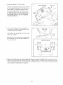
1, Make sure that the power cord is unplugged.
With the help of a second person, carefully tip
the treadmill onto its left side as shown, Partially
fold the Frame (26) so that the treadmill is more
stable, Do not fully fold the Frame until the
treadmill is completely assemMed.
identify the Right Upright (76) which has a
RIGHT sticker, Hold the Right Upright near the
Base (81), insert the Upright Wire (75) into the
Right Upright until the Upright Wire is extending
from the upper end of the Right Upright, Note:
Make sure that the Upright Wire is extending
from the side of the post as shown in the inset
drawing, Remove the tie from the Upright Wire,
Thread a 2 3/4" Upright Bolt (85) and a 1" Upright
Bolt (84) with 3/8" Star Washers (83) into the
Base (81) and the bottom of the Right Upright
(76), Do not tighten the Upright Bolts yet,
76
26
83
SHdea FrontEndcap(80)ontotheBase(81).
tightena EndcapScrew(79)intothe
2. Partiafly
FrontEndcapandthebase,
2
_
79
81
8O
Sfidea WheeU
Housing(86)ontotheBase(81).
AttachtheWheeU
Housingwitha 1"TekScrew
(77)anda BasePad(89)witha 1 1/4"Tek
Screw(108)asshown,
86
AttachanadditionaU
BasePad(89)to theBase
(81)witha 1"TekScrew(77),
WiththeheUp
ofa secondperson,carefuflytip
thetreadmHU
ontoitsrightsideasshown,
Partiafly
feudtheFrame(26)so thetreadmHU
is
morestaMe.Donotfully fold the Frameuntil
the treadmillis completelyassembled.
81
70
HoUd
theLeftUpright(70)againsttheBase(81).
Then,threada 2 3/4"UprightBoUt
(85)anda 1"
UprightBoUt
(84)with3/8"StarWashers(83)into
theBase(81)andthebottomoftheLeftUpright
(70),Donottightenthe UprightBoltsyet.
26
Slidea FrontEndcap(80)ontotheBase(81).
Partiallytightena EndcapScrew(79)intothe
FrontEndcapandtheBase,
Slidea WheelHousing(86)ontotheBase(81).
AttachtheWheelHousingwitha 1"TekScrew
(77)anda BasePad(89)witha 1 1/4"Tek
Screw(108)asshown,
8O
79
81
86
AttachanadditionalBasePad(89)to theBase
(81)witha 1"TekScrews(77),
89
77
ofa secondperson,carefullyraise
5, WiththeheUp
theLeftUpright(70)andthe RightUpright(not
shown)toa vertbaU
position,
5
Removetheknobfromthepin,Makesurethat
thecollarandthespringareonthepin,(Note:if
therearetwocollars,pUace
oneon eachsideof
thespring,)Then,insertthepinintotheLatch
Housing(71),andtightentheknobontothepin,
Seesteps2 and4.Fullytightenthe two
EndcapScrews(79}.
Collar
Pin
6, Slidea Handrail(62)ontothepostonthe Left
Upright(70),Fingertightentwo1 1/4"Bolts(63)
intotheHandrailandthepost;do notfully
tightenthe BoJtsyet.
63
Post
62
AttachtheotherHandrail(62)totheRight
Upright(76)inthesameway,
62
MakesurethattheUprightWire(75)is posio
tionedatthesideofthepostonthe Right
Upright(76)asshown,
65
SetthePulseBar(66)ontheLeftandRight
Uprights(70,76),Attachthe PulseBarwithfour
SilverPulseBarScrews(64)andfourPulseBar
StarWashers(65),Startallfour SilverPulse
BarScrewsbeforefirmly tighteningthem.
63
64
66
Firmlytightenthe four 1 1/4"BoJts(63}.
7O
63
8
While a second person holds the console as°
sembly near the Pulse Bar (66), connect the
Ground Wire (107) on the Pulse Barto the
ground wire from the console assembly,
Connect the wire from the console assembly to
the Upright Wire (75), Make sure to connect
the connectors properJy (see the inset drawing}. The connectors shouJd sJide together
easiJy and snap into place, if the connectors
do not slide together easily and snap into place,
turn one connector and then try again, IF THE
CONNECTORS ARE NOT CONNECTED
Console
Assembly
Ground
Wire
PROPERLY, THE CONSOLE MAY BE DAMAGED WHEN THE POWER mSTURNED ON.
Lay the wires inside the bottom of the Pulse Bar
(66),
66
Set the console assembly on the Left and Right
Uprights (70, 76), Be careful not to pinch any
wires.
Console Assembly
Attach the console assembly to the Pulse Bar
(66) with six 3/4" Screws (23), Start all six
Screws, before tighten them yet.
23
23
23
--76
10, identify the Left Handrail Cover (68), which has
a LEFT sticker on it, Slide the Left Handrail
Cover onto the left Handrail (62) and up against
the console assembly, Tighten two Cover
Screws (52) into the Left Handrail Cover and the
Left Upright (70); be careful not to overtighten
the Cover Screws.
10
70--
Console
Assembl,
68
62
Attach the Right Handrail Cover (74) in the same
way,
52
52
11,LowertheUprights(70,76)asshown,
11
StartthetwoindicatedConsoleScrews(67)into
theLeftandRightUprights(70,76)andtheconsob assembly,
if necessary,
pullbackonthe
consoleassemblyslightlytoalignthehobsin
theUprightswiththoseontheconsoleassembly,Starttheothertwo ConsoJe
Screwsbe_
foretighteningaHfour; do not overtighten
the ConsoleScrews.
ConsoleAssembly
Start
First
StartFirst
7O
76
12,Seetheinsetdrawing,PushtheUprights(70,
76)sidewayssothatthetreadmillFrame(26)is
centeredbetweentheUprights,
12
SideView
70,76
Firmlytightenthe UprightBolts(84,85)on each
sideofthetreadmill,
WiththeheUp
ofa secondperson,carefullyraise
theLeftUpright(70)andthe RightUpright(76)
toa verticalposition
26
View From Above
m
70 /
13, Make sure that aH parts are properly tightened before you use the treadmill, if there are sheets of clear
plastic on the treadmill decals, remove the plastic, To protect the floor or carpet, place a mat under the tread°
mill, Note: Extra hardware may be included, Keep the included hex key in a secure place; the large hex key is
used to adjust the walking belt (see page 23),
10
mfyou purchase the optional chest puJse sensor (see page 19), follow the steps below to install the receiver
included with the chest pulse sensor.
1, Remove the key from the console and unplug
the power cord.
Remove the 3/4" Screw (23) and the Access Door
(100) from the back of the ConsoUe Base (98),
I
2, Connect the wire on the receiver (A) to the indicated wire extending from the Console Base (98),
HoJd the receiver so the small cylinder is oriented as shown and is facing the ConsoJe
Base. Attach the receiver to the pUastb posts on
the Access Door (100) with the two included
small screws,
3, Make sure that no wires are pinched. Reattach
the Access Door (100) with the 3/4" Screw (23),
Discard the other wires included with the receiver,
11
/
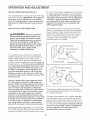
OPERATION
AND ADJUSTMENT
THE PRE-LUBRmCATED WALKmNG BELT
tric shock. This product is equipped with a cord having
an equipment-grounding conductor and a grounding
plug, Plug the power cord into a surge suppressor,
and pJug the surge suppressor into an appropriate
outlet that is properly installed and grounded in
accordance with aH JocaJ codes and ordinances.
Your treadmHUfeatures a waUking beUtcoated with high°
performance Uubrbant, IMPORTANT: Never apply silicone spray or other substances to the waJking
beJt or the walking platform. Such substances will
deteriorate the walking belt and cause excessive
wear.
Important: The treadmill
GFOl-equipped outJets.
HOW TO PLUG IN THE POWER CORD
is not compatible
with
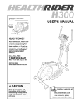
This product is for use on a nominal 120-volt circuit,
and has a grounding plug that looks like the plug illustrated in drawing 1 below, A temporary adapter that
looks like the adapter illustrated in drawing 2 may be
used to connect the surge suppressor to a 2-pole
receptacle as shown in drawing 2 if a properly
grounded outlet is not available,
DANG ER: Improper
connection
of the equipment-grounding
conductor can
resuJt in an increased risk of eJectric shock.
Check with a qualified eJectrician or serviceman if you are in doubt as to whether the
product is properly grounded. Do not modify
the plug provided with the productJif
it wHJ
not fit the outlet, have a proper ouUet
installed by a quaJified eJectrician.
I
¢-1
_
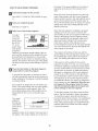
Your treadmill, like any other type of sophisticated
electronic equipment, can be seriously damaged by
sudden voltage changes in your home's power,
Voltage surges, spikes, and noise interference can
result from weather conditions or from other appliances
being turned on or off, To decrease the possibility of
your treadmill being damaged, aJways use a surge
suppressor with your treadmill (see drawing 1 at
the right). To purchase a surge suppressor, see
your tocaJ NealthRider dealer or can the toN-free
teJephone number on the front cover of this manual and order part number 146148, or see your JocaJ
electronics store.
['_
-Grounded
Outlet Box
_
9urge Suppressor
IS_.
_rounded Outlet
Grounding Pin
Grounding Plug"_
2
_rounded Outlet Box
Adapter
Use onJy a single-outlet surge suppressor that is
UL 1449 Jisted as a transient voltage surge suppressor (TVSS}. The surge suppressor must have a
UL suppressed vottage rating of 400 volts or tess
and a minimum surge dissipation of 450 joules.
The surge suppressor must be electrically rated for
120 volts AC and 15 amps. There must be a monitoring Hght on the surge suppressor to indicate
whether it is functioning properly. Failure to use a
properJy functioning surge suppressor could resuJt
in damage to the controt system of the treadmill. If
the control system is damaged, the waJking belt
may change speed, accelerate or stop unexpectedly, which may result in a fail and serious injury.
Surge Suppressor
The temporary adapter should be used only until a
properly grounded outlet (drawing 1) can be installed
by a qualified electrician,
The greenocolored rigid ear, lug, or the like extending
from the adapter must be connected to a permanent
ground such as a properly grounded outlet box cover,
Whenever the adapter is used it must be held in place
by a metal screw, Some 2-poJe receptacle outJet box
covers are not grounded. Contact a qualified electrician to determine if the outlet box cover is
This product must be grounded. If it should malfunc°
tion or break down, grounding provides a path of least
resistance for electric current, reducing the risk of ebc°
grounded
12
before using an adapter.
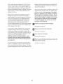
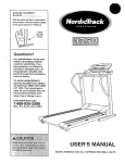
CONSOLE DmAGRAM
/
z
L
L
_J
J
Note: If there is a sheet of clear plastic
on the face of the console, remove it.
FEATURES OF THE CONSOLE
In addition, the console features four preset programs,
Each program automatically controls the speed and indine of the treadmill as it guides you through an effective workout, The console also features four calorie programs that automatically control the speed and incline
of the treadmill to help you burn unwanted pounds during your workouts,
The treadmill console offers an impressive array of
features designed to make your workouts more effective.
When the manual mode of the console is selected, the
speed and incline of the treadmill can be changed with
the touch of a button. As you exercise, the console will
display continuous exercise feedback. You can even
measure your heart rate using the built-in handgrip
pulse sensor or the optional chest pulse sensor (see
page 19).
To use the manuat mode of the console, follow the
steps beginning on page 14. To use a preset
program, see page 16. To use a calorie program,
see page 17.
13
HOW TO TURN ON THE POWER
if you have selected a program, reselect the manual mode by pressing any of the buttons numbered P1 to P8 once or twice until a track appears
in the lower part of the display,
Hug in the power cord (see page 12),
Locate the reset/off
circuit breaker near
the power cord, Make
sure that the circuit
breaker is in the reset
position,
Start the walking
Reset
Position
belt.
To start the walking belt, press the Start button,
the Quick Speed increase button, or one of the
speed buttons numbered 1 to 10,
if the Start button or the Quick Speed increase
button is pressed, the walking belt wiii begin to
move at 1 mph, As you exercise, change the
speed of the walking belt as desired by pressing
the Quick Speed increase and decrease
buttons, Each time a
Stand on the foot rails of the treadmill Find the dip
attached to the key (see the drawing on page 13)
and slide the dip onto the waistband of your
clothes, Next, insert the key into the consob, After
a moment, the display wii[ light, important: in an
emergency situation, the key can be pulled
from the console, causing the walking belt to
slow to a stop. Test the clip by carefully taking
a few steps backward; if the key is not putled
from the console, adjust the position of the
clip.
button is pressed, the
speed setting wiii
change by 0,1 mph; if a
button is held down, the
speed setting will change in increments of 0,5
mph, Note: After the buttons are pressed, it may
take a moment for the walking belt to reach the selected speed setting,
if one of the numbered speed buttons is pressed,
the walking belt wiii gradually increase in speed
until it reaches the selected speed setting,
insert the key into the console.
See HOW TO TURN ON THE POWER above,
To stop the walking belt, press the Stop button,
The time will begin to flash in the display, To
restart the walking belt, press the Start button, the
Quick Speed increase button, or one of the numbered buttons,
Enter your weight if desired.
if you enter your weight
into the console, the
console wiii display a
more accurate estimate
of the number of calo-
;9S
bS
mmmEm
Note: The first time the treadmill is used, observe
the alignment of the walking belt, and align the
walking belt if necessary (see page 23),
B
m
m
ries that you burn, To
enter your weight, press the weight increase and
decrease buttons repeatedly, Note: Once you have
entered your weight, it wiii be saved in memory,
Change the incline of the treadmill
To change the incline of
the treadmill, press the
Power Incline increase
Select the manual mode.
When the
key is inserted, the
manual
mode wiii
be selected,
as desired.
Ir
U
_.cu_
and decrease buttons,
T,ME 9'S
S
Each time a button is
pressed, the incline will
change by 0,5%, Note: After the buttons are
pressed, it may take a moment for the treadmill to
reach the selected incline setting,
IEaMaWM_JMaW
Track
14
Follow your progress with the display.
Measure your heart rate if desired.
When the
manual
mode is sebcted, the
bwer part of
the dispUay
wHUshow a
Note: if you
use the
__
m
handgrip
pulse sensor
and the optional chest
Track
Contacts
pulse sensor
at the same
time, the
console will not display your heart rate accurately,
Before using the handgrip pulse sensor, remove
the clear plastic film from the metal contacts, in
addition, make sure that your hands are clean,
1/4-mile track. As you waUkor run, the indicators
around the track wH]appear in succession until the
entire track appears. The track wH]then disappear
and the indicators wH]again begin to appear in
succession,
The left side of the display wiii show the incline
level of the treadmill, the
elapsed time, and the
distance you have
walked or run, Note:
To measure your heart rate, stand on the foot
rails and hold the metal contacts on the
handrail--avoid
moving your hands. When your
pulse is detected, the heart symbol in the right side
of the display will appear, one or two dashes will
appear, and then your heart rate will be shown.
For the most accurate heart rate reading, continue to hotd the contacts for about 15 seconds.
When a program is selected, the display wiii show
the time remaining in the program instead of the
elapsed time,
The right side of the
display wiii show the
speed of the walking
belt, the approximate
number of calories you
have burned, and your
pace (in minutes per mile), The display will also
show your heart rate when you use the handgrip
pulse sensor or the optional chest pulse sensor,
Turn on the fan if desired.
To turn on the fan at low speed, press the Cool
Breeze Fan button. To turn on the fan at high
speed, press the button a second time. To turn off
the fan, press the button a third time. Note: if the
fan is left on when the walking belt is stopped, the
fan will automatically turn off after a few minutes.
To reset the display, press the Stop button, remove the key, and then reinsert the key.
When you are finished
key from the consote.
Note: The console can
Step onto the foot rails, press the Stop button, and
adjust the incline of the treadmill to the Jowest
setting. The incline must be at the Jowest setting
when the treadmill is fotded to the storage position or the treadmill will be damaged. Next, remove the key from the console and put it in a secure place. Note: If the display remains Jit after
the key is removed, the consoJe is in the
"demo" mode. See page 19 and turn off the
demo mode.
display speed and distance in either miles or
kilometers, To determine
which unit of measure°
ment is selected, hold
down the Stop button while inserting the key into
the console, An "E" for English miles or an "M" for
metric kilometers will appear in the right side of the
display, Press the Quick Speed increase button to
change the unit of measurement, When the desired unit of measurement is selected, remove the
key, Note: For simplicity, aH instructions in this
section refer to miles.
exercising,
remove the
When you are finished using the treadmill,
switch the reset/off circuit breaker to the off
position
15
and unptug the power cord.
the matrix,) The speed settings for the next four
segments will be shown in the columns to the
right,
HOW TO USE A PRESET PROGRAM
insert the key fuity into the consote.
When only three seconds remain in the first segment of the program, both the Current Segment
column and the column to the right will flash and a
series of tones will sound, if the speed and/or incline of the treadmill is about to change, the speed
setting and/or the incline setting wiii flash in the
display to alert you,
See HOW TO TURN ON THE POWER on page
14.
Enter your weight if desired.
See step 2 on page 14.
When the first segment is completed, aiiepeed
eettinde
wiii
me_'e eriecei&,mntothe/eLl,
The
speed setting for the second segment wiii then be
shown in the flashing Current Segment column
and the treadmill will automatically adjust to the
speed and incline settings for the second segment. Note: if all five of the indicators in the
Current Segment column are lit, the e/xeed'eeff/b_:£
maFme_'e obwnwardso that only the highest indicators appear in the matrix.
Select one of the preset programs.
To select
one of the
2
5
SPEED
preset programs, press
_
CALORIE_
the P5, P6,
ATJJmBfWYA_
P7, or P8
_WH#Nmm#i_
fmmm__
PROGRAM
button. After
each preset
program is
selected, the maximum speed setting of the program and the maximum incline setting of the program wHi flash in the dispiay for a few seconds.
The dispiay wHi aiso show how iong the program
wHi Hast.The matrix in the Hewer part of the dispiay
wHi show the first seven speed settings of the program.
The program will continue in this way until the
speed setting for the last segment is shown in the
Current Segment column and the last segment
ends, The walking belt wiii then slow to a stop,
if the speed or incline setting for the current
segment is too high or too low, you can manually
override the setting by pressing the Quick Speed
or Power Incline buttons, Every few times a Quick
Speed button is pressed, an additional indicator
wiii appear or disappear in the Current Segment
column; if any of the columns to the right of the
Current Segment column have the same number
of lit indicators as the Current Segment column,
an additional indicator may appear or disappear in
those columns as well. important: When the current segment of the program ends, the treadmill will automatically adjust to the speed and
incline settings for the next segment.
Press the Start button or the Quick Speed increase button to start the program.
A moment after the button is pressed, the treadmHi wHi automaticaliy adjust to the first speed and
incline settings for the program, Hold the handrails
and begin waiking,
Each program is divided into 30 one-minute segments, One speed setting and one incline setting
are programmed for each segment, Note: The
same speed setting and/or incline setting may be
programmed for two or more consecutive segments,
The speed
setting for
the first segment will be
shown in the
__
To stop the program at any time, press the Stop
button, The time wiii begin to flash in the display,
To restart the program, press the Start button or
the Quick Speed increase button, The walking belt
will begin to move at 1 mph, When the next segment of the program begins, the treadmill will automatically adjust to the speed and incline settings
for the next segment,
PROGRAM
CurrLnt Segment
flashing
Current
Segment column of the matrix in the lower part of
the display. (The incline settings are not shown in
16
Fottow your progress with the display.
NOW TO USE A CALORIE PROGRAM
See step 6 on page 15,
Insert the key into the consote.
Measure your heart rate if desired.
See step 7 on page 15,
See HOW TO TURN ON THE POWER on page
14,
Turn on the fan if desired.
Enter your weight.
See step 8 on page 15,
See step 2 on page 14, Note: Always enter your
weight before using a calorie program; the
speed and incline settings of the program witt
depend on the weight setting that you enter.
When you are finished
key from the consote.
exercising,
remove the
Select a caJode program.
When the program has ended, make sure that
the incline of the treadmill is at the towest set-
To select a
calorie program, press
the P1, P2,
P3, or P4
button, After
each calorie
program is
selected, the
maximum speed setting of the program and the
maximum incline setting of the program wiii flash
in the display for a few seconds, The display will
also show how long the program will last, The matrix in the lower part of the display wiii show the
first seven speed settings of the program,
ting. Next, remove the key from the consob and
put it in a safe pUace,Note: If the display remains
tit after the key is removed, the consote is in
the "demo" mode. See page 19 and turn off the
demo mode.
p,,
When you are finished using the treadmill,
switch the reset/off circuit breaker to the "off"
position and unplug the power cord.
Press the Start button to start the program.
A moment after the button is pressed, the treadmill will automatically adjust to the first speed and
incline settings of the program, Hold the handrails
and begin walking,
Each program is divided into 30, 35, 40, or 45
one-minute segments, One speed setting and one
incline setting are programmed for each segment,
Note: The same speed setting and/or incline setting
may be programmed for two or more consecutive
segments,
The speed
setting for
the first segment wiii be
shown in the
flashing
Current
_lmw
_mlmm
mmm_mmtlfimllm
If#AH_
PROGRAM
Current Segment
Segment column of the matrix, (The incline settings are not shown in the matrix,) The speed settings for the next four segments wiii be shown in
the columns to the right,
17
When only three seconds remain in the first segment of the program, both the Current Segment
column and the column to the right will flash and a
series of tones will sound, if the speed and/or incline of the treadmill is about to change, the speed
setting and/or the incline setting will flash in the
display to alert you,
segment of the program begins, the treadmill wiii
automatically adjust to the speed and incline settings for that segment,
The program will continue in this way until the last
segment of the program ends, The walking belt
wili then slow to a stop, Important: The calorie
goal is an estimate of the number of calories
that you will burn during the program. The actual number of calories that you burn wilt depend on your weight. In addition, if you manually change the speed or incline of treadmill
during the program, the number of caJories
you burn wilt be affected.
When the first segment is completed, allspeed
,_d_/,q_:£
, w?//moYe one coldmn /o the le/./, The
speed setting for the second segment will then be
shown in the flashing Current Segment column
and the treadmill will automatically adjust to the
speed and incline settings for the second segment, Note: if all five of the indicators in the
Current Segment column are lit, the speed settings
may move downward so that only the highest indicators appear in the matrix,
Fottow your progress with the display.
if the speed or incline setting for the current segment is too high or too low, you can manually
override the setting by pressing the Speed and
Incline buttons, Every few times a Speed button is
pressed, an additional indicator wiii appear or disappear in the Current Segment column,
Important: When the current segment of the
program ends, the treadmill will automatically
adjust to the speed and incline settings for the
next segment.
Measure your heart rate if desired.
To stop the program at any time, press the Stop
button, To restart the program, press the Start button or the Quick Speed increase button, The walking belt will begin to move at 1 mph, When the next
See step 8 on page 17,
See step 6 on page 15,
See step 7 on page 15,
Turn on the fan if desired.
See step 8 on page 15,
When you are finished
key from the consote.
18
exercising,
remove the
THE INFORMATION
MODE/DEMO MODE
THE OPTIONAL
The consoUe features an information mode that keeps
track of the totaUnumber of hours that the treadmHUhas
been operated and the totaUnumber of miles that the
waUking beUthas moved. The information mode aUsoaP
bws you to sebct miles or kilometers as the unit of
measurement and to turn on and turn off the demo
mode.
An optional chest pulse sensor adds even more features to the console, The chest pulse sensor offers
hands-free operation, and enables you to use the consob's two heart rate programs, To purchase the optional chest pulse sensor, call the toil-free telephone number on the front cover of this manual
To sebct the information mode, hoUddown the Stop
button while inserting the key into the consob. When
the information mode is sebcted, the following information wHUbe shown in the dispUay:
The bft side of the display
will show the total number of
miles (or kilometers) that the
walking belt has moved and
the total number of hours
that the treadmill has been
CHEST PULSE SENSOR
E
Mile Is _gHours
used, An "E" for English miles or an "M" for metric kilo°
meters wiii appear in the right side of the display, Press
the Quick Speed increase button to change the unit of
measurement,
IMPORTANT: if a "d" appears in the right side of the
display, the console is in the "demo" mode. This mode
is intended to be used only when a treadmill is displayed in a store. When the console is in the demo
mode, the power cord can be plugged in, the key can
be removed from the console, and the indicators in the
display will automatically appear in a preset sequence,
although the buttons on the console will not operate. If a
"d" appears when the information mode is selected,
press the Quick Speed decrease button so the "d"
disappears.
To exit the information mode, remove the key from the
console,
19
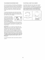
HOW TO FOLD AND MOVE THE TREADMmLL
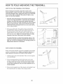
HOW TO FOLD THE TREADMmLL FOR STORAGE
Before foJding the treadmill, adjust the incline to the
towest position, mfthis is not done, the treadmill may be permanently damaged. Next, unplug the power cord. CAUTmON:
You must be abJe to safely lift 45 pounds (20 kg) to raise,
tower, or move the treadmill.
1, Hold the metaJ frame firmly in the location shown by the
arrow at the right. CAUTmON: To decrease the possibility
of injury, do not lift the frame by the plastic foot rails.
Make sure to bend your Jegs and keep your back straight.
As you raise the frame, make sure to Jilt with your tegs
rather than with your back. Raise the frame about halfway
to the vertical position,
-rame
2, Move your right hand to the position shown and hold the
treadmill firmly, Using your left hand, pull the latch knob to
the left and hold it, Raise the frame until the latch pin is
aligned with the hole in the center of the cushion, Slowly release the latch knob, Make sure that the latch pin is fully
inserted in the hote in the center of the cushion.
To protect the floor or carpet from damage, place a mat
under the treadmill
Keep the treadmill out of direct suntight. Do not leave the treadmill in the storage position in
temperatures above 85 ° Fahrenheit.
Latch
HOW TO MOVE THE TREADMmLL
Before moving the treadmill, convert the treadmill to the storage
position as described above, Make sure that the tatch pin is
fully inserted in the hote in the center of the cushion.
1, Hold the upper ends of the handrails, Place one foot against
one of the wheels,
2, Tilt the treadmill backward until it rolls freely on the
wheels, Carefully move the treadmill to the desired
To reduce the risk of injury, use extreme caution
moving the treadmill. Do not move the treadmill
uneven
Handrail
front
location,
while
over an
surface.
Wheel
3, Place one foot against one of the wheels, and carefully lower
the treadmill until it is resting in the storage position,
20
HOW TO LOWER THE TREADMmLL FOR USE
1, HoUdthe upper end of the treadmHUwith your right hand, PuN
the latch knob to the bft and hoUdit, Pivot the frame down°
ward until the catch is past the Uatchpin,
/
Frame
Open
.Latch Knob.
Latch Pin-
2, Hold the meta! frame firmly with both hands, and bwer it to
the floor, CAUTION: To decrease the possibility of injury, do
not lower the frame by gdpping only the plastic foot rails.
Do not drop the frame to the floor. Make sure to bend your
legs and keep your back straight.
Frame
21
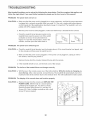
TROUBLESHOOTmNG
Most treadmill problems can be solved by following the steps below. Find the symptom that applies, and
follow the steps listed, mfyou need further assistance, please see the front cover of this manual.
PROBLEM:
The power does not turn on
SOLUTmON: a, Make sure that the power cord is plugged into a surge suppressor, and that the surge suppressor
is plugged into a properly grounded outlet (see page 12). Use only a single-outlet surge suppressor that meets all of the specifications described on page 12. important: The treadmill is not compatible with GFCl-squipped outlets.
b. After the power cord has been plugged in, make sure that the key is inserted into the consols.
C,
Check the reset/off circuit breaker located on the
treadmill frame near the power cord. if the switch
protrudes as shown, the circuit breaker has
tripped. To reset the circuit breaker, wait for five
minutes, and then press the switch back in.
Tripped
PROBLEM:
The power turns off during
use
SOLUTION:
a. Check the reset/off circuit breaker (see the drawing above), if the circuit breaker has tripped, wait
for five minutes and then press the switch back in.
b. Make sure that the power cord is plugged in. if the power cord is plugged in, unplug it, wait for
five minutes, and then plug it back in.
c. Remove the key from the console. Reinsert the key into the console.
d. if the treadmill still will not run, see the front cover of this manual.
PROBLEM:
The incline of the treadmill
does not change correctly
SOLUTmON: a. With the key in the console, press one of the Incline buttons. While the incline is changing, remove the key. After a few seconds, re-insert the key. The treadmill will automatically rise to the
maximum incline level and then return to the minimum level. This will recalibrate the incline system.
PROBLEM:
The disptay of the console
does not function
property
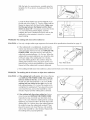
SOLUTmON: a, Remove the key from the console and UNPLUG THE
POWER CORD. With the help of a second person,
carefully tip the Uprights (70, 76) down as shown,
Remove the three Hood Screws (11 ) and two 3/4"
Screws (23), Note: A phillips screwdriver with a shaft
at bast 5" long is required.
22
11
23
With the heUpof a second person, carefully raise the
Uprights (70, 76) as shown, Carefully pivot the Hood
(28) off,
Locate the Reed Switch (39) and the Magnet (6) on
the bft side of the Pulley (7), Turn the Pulley until the
Magnet is aligned with the Reed Switch, Make sure
that the gap between the Magnet and the Reed
Switch is about 1/8", if necessary, bosen the Screw
(11), move the Reed Switch slightly, and then
retighten the Screw, Reattach the Hood, and run the
treadmHUfor a few minutes to check for a correct
speed reading,
PROBLEM:
SOLUTION:
The walking
1/8"11 /
7
[
Top
View
belt slows when walked on
a, Use only a singleooutlet surge suppressor that meets all the specifications described on page 12,
b,
if the walking belt is overtightened, treadmill perforo
mance may decrease and the walking belt may beo
come damaged, Remove the key and UNPLUG THE
POWER CORD, Using the hex key, turn both rear
roller bolts counterclockwise, 1/4 of a turn, When the
walking belt is properly tightened, you should be able
to lift each edge of the walking belt 2 to 3 inches
above the walking platform, Be careful to keep the
walking belt centered, Then, plug in the power cord,
insert the key, and run the treadmill for a few minutes,
Repeat until the walking belt is properly tightened,
Rear Roller Bolts
c, if the walking belt still slows when walked on, please see the front cover of this manual,
PROBLEM:
The waJking belt is off-center
or slips when walked on
SOLUTION:
a, If the waJking beJt is off-center, first remove the key
and UNPLUG THE POWER CORD, If the walking
belt has shifted to the Jeft, use the hex key to turn
the left rear roller bolt clockwise 1/2 of a turn; if the
walking belt has shifted to the right, turn the left
bolt counterclockwise 1/2 of a turn, Be careful not to
overtighten the walking belt, Then, plug in the power
cord, insert the key, and run the treadmill for a few
minutes, Repeat until the walking belt is centered,
b,
If the walking belt slips when walked on, first remove the key and UNPLUG THE POWER CORD,
Using the hex key, turn both rear roller bolts clock°
wise, 1/4 of a turn, When the walking belt is correctly
tightened, you should be able to lift each edge of the
walking belt 2 to 3 inches above the walking platform,
Be careful to keep the walking belt centered, Then,
plug in the power cord, insert the key, and carefully
walk on the treadmill for a few minutes, Repeat until
the walking belt is properly tightened,
23
CONDiTiONiNG
WARNING:
GUiDELiNES
Before
beginning
the
or any exerciseprogram, consuJtyour physi°
cianoThis isespeciallyimportantforindividu_
als over the age of 35 or individuals with pre_
existing health problems.
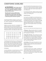
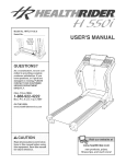
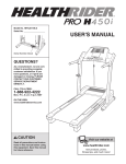
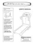
Aerobic
EXERCISE iNTENSiTY
Whether your goal is to burn fat or to strengthen your
cardiovascular system, the key to achieving the
desired results is to exercise with the proper intensity,
The proper intensity level can be found by using your
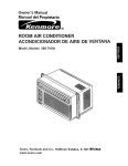
heart rate as a guide, The chart below shows recommended heart rates for fat burning and aerobic exercise,
145 138
130 125
125 120
115
110 105
95
20
40
50
70
30
118 110
60
115
_
103
C_
Exercise
if your goal is to strengthen your cardiovascular sys=
tem, your exercise must be "aerobic," Aerobic exercise
is activity that requires large amounts of oxygen for
prolonged periods of time, This increases the demand
on the heart to pump blood to the muscles, and on the
lungs to oxygenate the blood, For aerobic exercise,
adjust the speed and incline of the treadmill until your
heart rate is near the highest number in your training
zone,
The following guidelines wiii help you to plan your exercise program, For more detailed exercise informa=
tion, obtain a reputable book or consult your physician,
140 130 125
your body
if your goal
of the tread:
number in
For maximum fat burning, adjust the speed and incline
of the treadmill until your heart rate is near the middle
number in your training zone,
The puJse sensor is not a medical device.
Various factors, including your movement,
may affect the accuracy of heart rate readings.
The sensor is intended onty as an exercise aid
in determining heart rate trends in general
165 155 145
ergy, Only after the first few minutes does
begin to use stored fatc,-2/briesfor energy,
is to burn fat, adjust the speed and incline
mill until your heart rate is near the lowest
your training zone,
WORKOUT
GUiDELiNES
Each workout should include the following three parts:
A Warm-up--Start
each workout with 5 to 10 minutes
of stretching and light exercise, A proper warm-up increases your body temperature, heart rate and circulation in preparation for exercise,
Training Zone Exercise--After
warming up, increase
the intensity of your exercise until your heart rate is in
your training zone for 20 to 60 minutes, (During the
first few weeks of your exercise program, do not keep
your heart rate in your training zone for longer than 20
minutes,) Breathe regularly and deeply as you exer=
cise--never hold your breath,
90
80
To find the proper heart rate for you, first find your age
near the bottom of the chart (ages are rounded off to
the nearest ten years), Next, find the three numbers
above your age, The three numbers define your "train=
ing zone," The lower two numbers are recommended
heart rates for fat burning; the higher number is the
recommended heart rate for aerobic exercise,
A CooFdown--Finish
each workout with 5 to 10 min-
utes of stretching to cool down, This will increase the
flexibility of your muscles and will help prevent postexercise problems,
EXERCISE FREQUENCY
Fat Burning
To maintain or improve your condition, complete three
workouts each week, with at bast one day of rest between workouts, After a few months, you may corn=
plete up to five workouts each week if desired, The key
to success is to make exercise a regular and enjoyable
part of your everyday life,
To burn fat effectively, you must exercise at a relatively
low intensity level for a sustained period of time,
During the first few minutes of exercise, your body
uses easily accessible oaris_oiTyc/?3te
o31briesfor en:
24
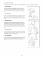
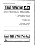
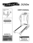
SUGGESTED STRETCHES
The correct form for several basic stretches is shown at the right, Move slowly as you stretch--never
bounce,
1. Toe Touch Stretch
Stand with your knees bent slightly and slowly bend forward from
your hips, Allow your back and shoulders to relax as you reach
down toward your toes as far as possible, Hold for 15 counts, then
relax, Repeat 3 times, Stretches: Hamstrings, back of knees and
back,
2. Hamstring
Stretch
Sit with one leg extended, Bring the sob of the opposite foot toward
you and rest it against the inner thigh of your extended leg, Reach
toward your toes as far as possible, Hold for 15 counts, then relax,
Repeat 3 times for each leg, Stretches: Hamstrings, lower back and
groin,
3. Caff/Achiltes
Stretch
With one leg in front of the other, reach forward and place your
hands against a wall, Keep your back leg straight and your back foot
fiat on the floor, Bend your front leg, ban forward and move your
hips toward the wall, Hold for 15 counts, then relax, Repeat 3 times
for each leg, To cause further stretching of the achilles tendons,
bend your back leg as well, Stretches: Calves, achilles tendons and
ankles,
4. Quaddceps
Stretch
With one hand against a wall for balance, reach back and grasp one
foot with your other hand, Bring your heel as dose to your buttocks
as possible, Hold for 15 counts, then relax, Repeat 3 times for each
leg, Stretches: Quadrieeps and hip muscles,
5. Inner Thigh Stretch
Sit with the sobs of your feet together and your knees outward, Pull
your feet toward your groin area as far as possible, Hold for 15
counts, then relax, Repeat 3 times, Stretches: Quadriceps and hip
muscles,
25
4
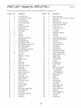
PART LIST--Model
No. HRTL61706.1
Roto7A
To Uocate the parts Hsted beUow,see the EXPLODED DRAWUNG on pages 28 to 31,
Key No.
Qty.
1
2
3
4
5
6
7
8
9
10
11
12
13
14
15
16
17
18
19
20
21
22
23
24
25
26
27
28
29
30
31
32
33
34
35
36
37
38
39
40
41
42
43
44
45
46
47
48
49
50
2
10
1
2
2
1
1
2
4
2
13
2
3
1
1
1
2
2
2
2
2
1
22
1
1
1
1
1
2
2
1
1
1
1
2
2
1
1
1
2
6
2
1
1
1
1
1
1
2
7
Description
Foot Rail Cover
Foot Rail Cover Screw
Left Foot Rail
Frame Pivot BoUt
Front Hatform BoUt
Magnet
Front RolledPulley
Platform Nut
Belt Guide Screw
Belt Guide
Screw
Isolator
Wire Tie
Latch Warning Decal
Walking Belt
Walking Platform
Rear Platform Bolt
Rear Roller Bracket Screw
Rear Roller Bracket
Rear Roller Bolt
Rear Roller Lock Washer
Left Rear Endcap
3/4" Screw
Hex Key
Right Rear Endcap
Frame
Right Foot Rail
Hood
Motor Bolt
Motor Nut
Motor Star Washer
Motor Belt
Drive Motor
Motor Bracket
Motor Tension Bolt
Motor Washer
Lift Frame
Reed Switch Clip
Reed Switch
Lift Frame Spacer
Pivot Nut
Caution Decal
Hairpin Cotter
Motor Pin
Lift Frame Ground Wire
Front Roller Bolt
Filter Wire
Front Roller Bushing
Tie Block
Plastic Tie
26
Key No.
Qty.
51
52
53
54
55
56
57
58
59
60
61
62
63
64
65
66
67
68
69
70
71
72
73
74
75
76
77
78
79
80
81
82
83
84
85
86
87
88
89
90
91
92
93
94
95
96
97
98
99
101
3
5
1
3
1
1
1
1
9
1
2
2
4
4
4
1
4
1
2
1
1
2
1
1
1
1
4
3
2
2
1
1
4
2
2
2
2
2
4
1
1
1
1
1
1
1
1
1
1
1
Description
Belly Pan Screw
Large Belly Pan Screw/Cover Screw
Belly Pan CHp
Reset/Off Circuit Breaker
Power Cord Grommet
Power Cord
Controller Bracket
1/2" Screw
Controller
Small Star Washer
Handrail
1,25" BoUt
SHver PuUse Bar Screw
PuUse Bar Star Washer
PuUse Bar
ConsoUe Screw
Left Handrail Cover
Handrail Cap
Left Upright
Latch Housing
Rear Roller Washer
Latch Pin AssemMy
Right Handrail Cover
Upright Wire
Right Upright
1" Tek Screw
Lift Bolt
Endcap Screw
Front Endcap
Base
Roller Ground Wire
3/8" Star Washer
1" Upright Bolt
2,75" Upright Bolt
Wheel Housing
Wheel Pin
Wheel
Base Pad
Incline Motor
Stop Bracket
Optic Disk
Photo Switch Nut
Photo Switch
Photo Switch Bolt
Key/Clip
Photo Switch Wire
Console Base
Console
Access Door
Key No.
Qty.
101
102
103
104
105
106
107
108
1
2
1
1
1
1
1
2
Description
Console Fan
Fan Screw
Static Decal
Rear Roller
Controller Wire
Front Roller Nut
Console Ground Wire
1 1/4" Tek Screw
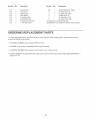
ORDERING
Key No.
Qty.
109
#
#
#
#
#
1
1
1
1
1
1
Description
Incline Motor Bolt, Upper
12" Blue Wire, 2F
12" Blue Wire, M/F
4" Blue Wire, 2F
22" Red Wire, M/F
20" Black Wire, M/F
"#" indicates a non-illustrated part.
Specifications are subject to change without notice.
REPLACEMENT
PARTS
To order replacement parts, see the front cover of this manual. When ordering parts, please be prepared to
provide the following information:
the MODEL NUMBER of the product (HRTL61706.1)
the NAME of the product (HealthRider
PRO H450i treadmill)
the SERIAL NUMBER of the product (see the front cover of this manual)
the KEY NUMBER and DESCRiPTiON
pages 26 to 31 )
of the part(s) (see the PART LiST and the EXPLODED DRAWING on
27
rT'l
X
0
II"1"1
l
Z
4
[
0
co
i
Z
18
0
m
Z
26
,-4
19
0
21
23
m
24
23
o
o
EXPLODED
DRAWING B--Model
No. HRTL61706.1
Rolo7A
11
\
\
\
---.%.
28
31
32
29
11
33 --
13
36
.35
37
41
48
43
44
46
53
_54
59
4O
54
58
55
57
47
29
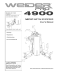
EXPLODED
DRAWING C--Model
No. HRTL61706.1
Rolo7A
_65
23
---107
J
23
66
_65
H
23
67
69
°3
23
i
i
70
i
i
62
J
J
69
71
_---79
76
73
41
83
41
78
_75
85
42
87
i
i
i
109
_89
80
&-108
81
77
78
88
_77
97
86
42 {_8_
84
3O
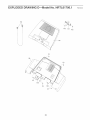
EXPLODED
DRAWING D--Model
No. HRTL61706.1
nolo7A
96
102
23
98
\
\
23
103
31
,,'
101
102
LiMiTED WARRANTY
WHAT IS COVERED--The
material and workmanship,
WHO
IS COVERED--The
entire
original
HealthRider
purchaser
HOW LONG IS IT COVERED--ICON
labor are warranted for one year from
PRO H450i treadmill
or any person
("Product")
receiving
is warranted
the Product
HeaIth&
Fitness, Inc, ("ICON"),
the date of purchase,
warrants
to be free of ail defects
as a gift from the original
in
purchaser,
the drive motor for 10 years,
Parts and
WHAT WE DO TO CORRECT
COVERED
DEFECTS--We
will ship to you, without charge, any replacement
part or
component,
providing the repairs are authorized
by ICON first and are performed
by an ICON trained and authorized
service provider, or, at our option, we wilI repIace the Product,
WHAT IS NOT COVERED--Any
failures or damage caused by unauthorized
service, misuse, accident, negligence,
im_
proper assembly or installation,
alterations,
modifications
without our written authorization
or by failure on your part to
use, operate, and maintain as set out in your User's ManuaI ("Manuai'),
This warranty does not extend to products used
for commercial
or rental purposes,
WHAT YOU MUST DO--Always
retain proof of purchase,
such as your bill of sale; store, operate, and maintain the
Product as specified in the Manual; notify our Customer
Service Department
of any defect within 10 days after discow
ery of the defect;
USER'S
as instructed,
MANUAL--It
return any defected
is VERY
Remember to do the periodic
continued
satisfaction,
HOW TO GET PARTS
IMPORTANT
maintenance
part for replacement
THAT
YOU
requirements
AND SERVICE--Simply
READ
specified
calI our Customer
or, if necessary,
THE
MANUAL
in the ManuaI
Service
the entire product,
before
to assure
Department
operating
proper
for repair,
the
operation
at 1_888_922o4222
Product,
and your
and tell them
your name and address and the seriaI number of your Product, They will tetI you how to get a part replaced, or if neces_
sary, arrange for service where your Product is located or advise you how to ship the Product for service, Before ship_
ping, aIways
your Product
obtain a Return Authorization
Number (RA No,) from our Customer
Service Department;
(save the original shipping carton if possible);
put the RA No, on the outside of the carton
product, Include a letter explaining
vice is covered by warranty,
ICON is not responsible
the product
or Iiable for indirect,
or problem
special
and a copy
or consequential
of your proof
damages
of purchase
arising
securely pack
and insure the
if you believe
out of or in connection
the ser_
with the
use or performance
of the product or damages with respect to any economic loss, loss of property, loss of revenues or
profits, Ioss of enjoyment
or use, costs of removal, installation
or other consequentia!
damages of whatsoever
nature,
Some
itation
states do not ailow the exclusion
may not appIy to you,
The warranty extended hereunder
or fitness for a particular purpose
aIIow limitations
This warranty
to change,
gives you specific
or consequenfiaI
warranty
lasts, Accordingly,
the above
modify or extend the terms of this limited
legai rights and you may have other
iCON HEALTH
Part No, 252194 R0107A
of incidental
damages,
Accordingly,
the above lim_
is in Iieu of any and alI other warranties
and any implied warranties
of merchantability
is limited in its scope and duration to the terms set forth herein, Some states do not
on how long an impIied
No one is authorized
or limitation
& FITNESS,
limitation
may not apply to you,
warranty,
rights which
mNC., 1500 S. 1000 W., LOGAN,
vary from state to state,
UT 84321o9813
Printed in USA © 2007 ICON IP, Inc,