1
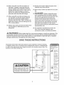
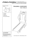
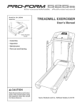
ModelNo.WLTL493040
SedalNo.
'S
WritethesedaU
numberin thespace
aboveforfuturereference,
SedaU
NumberDecaU
mfyou havequestions,or if there
aremissingparts,wewill guaranteecompletesatisfaction
throughdirectassistancefrom
ourfactory.
TOAVOIDDELAYS,PLEASE
CALLDIRECTTOOURTOLLFREECUSTOMER
HOTLINE.
Thetrainedtechnicianson our
CustomerNotLinewill provide
immediateassistance,freeof
chargeto you.
CUSTOMER
HOTMNE:
1°866-699-3756
Mon.-FrL
6 a.m.-6 p.m. MST
Read aH precautions
and !nstrucwwwowesmoocom
this
equipment. Save this mare
ual for future reference.
new products,
prizes,
fitness tips, and much more!
TABLE OF CONTENTS
iMPORTANT PRECAUTIONS .................................................................
BEFORE YOU BEGIN .......................................................................
ASSEMBLY AND PART HDENTHFHCATHON
CHART ................................................
TREADMILL OPERATION ...................................................................
HOW TO FOLD AND MOVE THE TREADMHLL ..................................................
TROUBLESHOOTHNG ......................................................................
EXERCISE GUiDELiNES
...................................................................
PART LiST ...............................................................................
HOW TO ORDER REPLACEMENT PARTS ..............................................
LHMHTEDWARRANTY ...............................................................
Note: An EXPLODED DRAWHNG is attached in the center of this manual
WESLO is a registered trademark of HCONHP,Hnc,
2
3
5
6
10
21
22
24
26
Back Cover
Back Cover
iMPORTANT
PRECAUTIONS
WARN raNG:Toreduce
the.skofburns,
fire,electric
shock,
orinjury
topersons,
read
the
folJowing
important
precautions
and information
1. mtis the responsibility
of the owner to ensure
that aH users of this treadmill are adequately
informed of all warnings and precautions.
2. Use the treadmill
manual
only as described
in this
3. Place the treadmill on a level surface, with at
least eight feet of clearance behind it and two
feet on each side. Do not pJace the treadmill
on any surface that blocks air openings. To
protect the floor or carpet from damage, place
a mat under the treadmill,
4. Keep the treadmill indoors, away from moisture and dust. Do not put the treadmHJ in a
garage or covered patio, or near water.
5. Do not operate the treadmill where aerosol
products are used or oxygen is administered,
8. Keep children under the age of !2 and pets
away from the treadmill at nit times.
7. The treadmill should not be used by persons
weighing more than 250 pounds. Never allow
more than one person on the treadmill at a time.
8. Wear appropriate exercise clothes when
using the treadmill. Do not wear loose clothes
that could become caught in the treadmill.
Athletic support clothes are recommended
for both men and women. Always wear athletic shoes. Never use the treadmill with bare
feet, wearing
only stockings,
or in sandals.
g. When connecting the power cord (see page 10),
pJug the power cord into a surge suppressor
(not included) and plug the surge suppressor
into a grounded circuit capable of carrying 15
or more amps. No other appJiance should be on
the same circuit. Do not use an extension cord.
10. Use onJy a singJe-ouflet surge suppressor that
meets aH of the specifications
described on
page 10. To purchase a surge suppressor, see
your Jocal WESLO dealer or call 1-888-8993758 and order part number 148148.
before operating
the treadmill.
11. FaiJure to use a properly functioning surge
suppressor couJd resuJt in damage to the con=
troJ system of the treadmill, if the control system is damaged, the waJking belt may change
speed or stop unexpectedJy, which may result
in a fall and serious injury.
12. Keep the power cord and the surge suppressot away from heated surfaces.
13. Never move the walking belt while the power
is turned off. Do not operate the treadmill if
the power cord or plug is damaged, or if the
treadmill is not working properly. (See
BEFORE YOU BEGmN on page 5 if the tread............................
14. Never start the treadmill while you are standing on the walking beff. AJways hold the
handrails while using the treadmill.
15. The treadmill is capabJe of high speeds.
Adjust the speed in smalt increments to avoid
sudden jumps In speed.
15. The pulse sensor is not a medicaJ device.
Various factors, including the user's movemeat, may affect the accuracy of heart rate
readings. The pulse sensor is intended only
as an exercise aid in determining heart rate
trends in general
17. Never leave the treadmill
unattended
while it
is running. Always remove the key, unplug
the power cord, and move the reset/off circuit
breaker to the off position when the treadmill
is not in use. (See the drawing on page 5 for
the location of the circuit breaker.}
18. Do not attempt to raise, tower, or move the
treadmill until it is properJy assembled. (See
ASSEMBLY on page 8, and HOW TO FOLD
AND MOVE THE TREADMILL on page 21.)
You must be able to safely mift45 pounds (20
kg) to raise, lower, or move the treadmill.
lg. When folding or moving the treadmill, make
sure that the storage latch is fuJly dosed.
20.When using iFIT.com CDs and videos, an
electronic "chirping"
sound will alert you
when the speed of the treadmit, is about to
change. Always listen for the "chirp" and be
prepared for speed changes, in some instances, the speed may change before the
personal trainer describes the change.
23. in spect and properly tighten all parts of the
treadmill every three months.
24. Never drop or insert any object into any opening,
25.DANG ER: Alwoys
unplug thepower
cord immediately after use, before cleaning
the treadmill, and before performing the main=
tenance and adiustment procedures de=
scribed in this manual Never remove the
21. When using iFmT.comCDs and videos, you
can manually override the speed setting at
any time by pressing the speed buttons.
However, when the next "chirp" is heard, the
speed wHJ change to the next settings for the
CD or video program.
motor hood unless instructed to do so by an
authorized service representative.
Servicing
other than the procedures in this manual
should be performed by an authorized service
representative
only.
22. Always remove iRT.com CDs and videos from
your CD player or VCR when you are not
using them.
26. The treadmi8 is intended for in-home use
only. Do not use the treadmill in any
commercial, rental, or institutional
setting.
WAR NmNG: Sefo,e
beginning
th soranyexercise
program,
oonsult
yourphysio an.
7his
is especially important for persons over the age of 35 or persons with pre-existing health problems.
Read aH instructions before using, mCONassumes no responsibility
for personal injury or property
damage sustained by or through the use of this product.
SAVE THESE mNSTRUCTIONS
The decals shown below have been ptaced on your treadmill, mfa decal is missing
or illegible, please call our Customer Service Department toll-free at 1-866-699-3756
to order a free replacement decal Apply the decal in the tocation shown. Note: The
decals are not shown actual size.
Protect yourself and
others from risk of serious
injury. Read the users
manual and :
side rails when
,Stand only on the
starting or stopping
treadmill,
,Change speed in
small inclements,
,Hold handrails to
provent falling, and
always wear the
salety clJp while
operating treadmill.
*Stop if you feel faint,
dizzy, or short ol
bleath,
mill is movedor
s_ored.
•Reduce incline to its
lowest level before.
folding _readmillinto
storage position1,
KEEPHANDSANDFEETAWAY
FROMTHISAREAWHILETHE
TREADMILL
IS INOPERATION.
not in use,
,Keep clothing,
fingers, and hair
it is moving,
,Always weal
athletic shoes while
opelating treadmill
4
BEFORE YOU BEGIN
Congratulations for purchasing the WESLO _ CADENCE C78 treadmill The CADENCE C78 treadmHU
using the treadmill, if you have questions after reading this manual, call our Customer Service Department
toll-free at 1-866-699°3756, Monday through Friday, 6
a,m, until 6 p,m, Mountain Time (excluding holidays),
To help us assist you, please note the product model
number and serial number before calling, The model
number is WLTL493040, The serial number can be
offers an impressive array of features to heUpyou
achieve your fitness goaUs in the convenience of your
home, From the advanced consob to the cushioned
waUking pUatform, the CADENCE C78 treadmHUis designed to make each workout more effective and enjoyabb, And when you're not exercising, the treadmHU
can be foUded away, taking bss than haUfthe floor
space of conventionaU treadmHb,
For your benefit,
read this manual carefully
found on a decal attached to the treadmill (see the
front cover of this manual for the location),
Before reading further, please familiarize yourself with
the parts that are labeled in the drawing below,
before
Fan
Accessory Tray
Console
Handrail
grip Pulse Sensor
Latch Knob
Key/Clip
Reset/Off Circuit Breaker
Walking Belt
Foot Rail
BACK
Cushioned Walking Platform
RIGHT SIDE
Rear Roller
5
Assembly requires two persons. Set the treadmill in a cleared area and remove all packing materials, Do not
dispose of the packing materials until assembly is completed, Note: The underside of the treadmill walking belt is
coated with high-performance lubricant, During shipping, a small amount of lubricant may be transferred to the
top of the walking belt or the shipping carton, This is a normal condition and does not affect treadmill performance, if there is lubricant on top of the walking belt, simply wipe off the lubricant with a soft cloth and a mild,
non-abrasive cleaner,
Assembty
requires
the incJuded allen wr_
wire cutters -_<,_z>,
rubber mallet _,
and your own phiJJips screwdriver
and adjustable
wrench
For help identifying the assembly hardware, refer to the drawings below, Note: The assembly hardware and other
small parts are packaged in separate part bags, Do not open the part bags untiJ instructed to do so. (The
part bags are not JabeJed according to the order in which they are to be opened.} If a part is not found in
the part bags, check to see if the part has been preassembted.
<szsq}@
3/4" Screw (6)-16
2" Silver Screw (93)-2
1 1/4" Screw (92)-2
1 1/4" Bolt (104)-4
1" Bolt (71)-2
Wheel Bolt (107)-2
D@H@
Internal Star
Washer (72)-4
Wheel Nut (21)-2
1, Open part bag B. identify the Right Upright (82) (the
Left Upright [69] has a large round hob in the location
shown), Lay the Right Upright fiat, Cut the plastic ties off
the lower end of the Right Upright, Next, feed the Wire
Harness (83) into the bottom of the Right Upright and
pull it out of the hob in the top, Note: There may be a tie
on the end of the Wire Harness to help you pull it
through the hob,
Attach the Right Upright (82) to the bracket on the right
side of the Base (109) with two 1 1/4" Bolts (104) and
two Internal Star Washers (72), (Note: it may be helpful
to use a rubber mallet to fully insert the Right Upright
into the bracket,) Do not tighten the BoJts yet. Be
carefut not to damage the Wire Harness.
Attach the Left Upright (69} to the teft side of the
Base (109} in the same way. Note: There is not a wire
harness on the left side,
6
5/16" Star
Washer (127)-2
69
Hole
109
Open part bag C. See drawing 2a, Locate the Wheel
Housings (106), Attach a Wheel (108) to each Wheel
Housing with a Wheel Bolt (107) and a Wheel Nut (21)
as shown, Do not overtighten the Wheel Bolts.
See drawing 2b, insert a Wheel Housing (106) into the
Base (109), (Note: it may be helpful to use a rubber mallet
to fully insert the Wheel Housing,) Press a Base Endcap
(99) onto the end of the Base,
Repeat this step on the opposite
2a
106
106
lO7 %
107
1O8
2b
108
_.
side of the treadmill.
99
106
With the help of a second person, carefully tip the
Uprights (69, 82) down so the treadmill pivots on the
Wheels (108) as shown,
69
Tighten a 3/4" Screw (6) into one side of the Base (109)
and one of the Wheel Housings (106), Attach a long Rear
Base Pad (105) and a short Front Base Pad (100) to the
Base with four additional 3/#' Screws (6) as shown,
Repeat this step on the opposite
100
105
side of the treadmill.
With the help of a second person, carefully raise the
Uprights (69, 82) to the vertical position,
106
6
109
108
105
108
With the help of a second person, hold the Console
Base (85) near the Uprights (69, 82) as shown,
Connect the Wire Harness (83) to the wire harness in
the Right Handrail Bracket (113), Make sure to connect
the connectors properly (see the inset drawing}. The
connectors should slide together easily and snap
into place, if the connectors do not slide together easily
and snap into place, turn one connector and try to connect them again, IF THE CONNECTORS ARE NOT
CONNECTED PROPERLY, THE CONSOLE MAY BE
DAMAGED WHEN THE POWER mSTURNED ON.
insert the wire harness into the Right Upright (82),
Open part bag A. Hold the Handrail Brackets (73, 113)
on top of the Uprights (69, 82), Finger tighten two 1"
Bolts (71) with 5/16" Star Washers (127) into the
Handrail Brackets and the tops of the Uprights as
shown, Press the Handrail Brackets towards the center of the treadmill. Then, tighten both Bolts,
73
85
113
82
HoHd
thePuHse
Bar(125)neartheConsoHe
Base(85),
Connectthe PuHse
Wire(124)onthe PuHse
Bartotheino
dicatedwireontheConsoHe
Base,Theconnectors
shouJdsJidetogethereasily and snap into place. Hf
the connectors do not slide together easily and snap into
pHace, turn one connector and try to connect them again,
Hnsertthe wires into the hoHein the ConsoHe Base,
Have a second person hoHdthe PuHse Bar (125) firmHyon
the ConsoHe Base (85), Attach the PuHseBar to the
ConsoHe Base with two ! 1/4" Screws (92) in the locations shown. Be careful not to damage the Pulse
Wire (!24} or the wire on the ConsoJe Base. Next,
tighten two 2" SHver Screws (93) into the ConsoHe Base
and the PuHse Bar in the Hocations shown, Note: The
correct Screws must be used in the correct loca-
92
125
tions, or the Pulse Bar may be damaged.
Hdentify the Left and Right HandraiHs (68, 81) (see the
end views of the HandraiHs in the inset drawing), The
curved edges of the HandraiHs shouHd be on the outside,
SHidethe Right HandraiH (81) onto the Right HandraiH
Bracket (113), and press the Hipon the front of the Right
HandraiH under the ConsoHe Base (85), (Note: Htmay be
heHpfuHto tip the Right HandraiH and to tap it with a rubber maHHetto correctly position it,) Tighten three 3/4"
Screws (6) into the Right HandraiH as shown, Note: Ht
may be necessary to move the Howerend of the Right
HandraiH sHightHyto aHignthe Hower screw hoHe,
6
68
-Curved Edge
Attach the Left Handrait (68} in the same way.
See assembly
(104).
step 1. Tighten the four 1 1/4" Bolts
(81)
(68)
Press the Latch Knob SHeeve (75) into the Left Upright
(69), Note: Htmay be heHpfuHto use a rubber maHHetto
fuHHyinsert the Latch Knob SHeeve,
Remove the Latch Knob (70) from the Latch Pin (80).
Make sure that the Latch Pin CoHHar(76) and the Spring
(77) are on the Latch Pin. (Note: Hfthere are two Latch
Pin CoHHars,pHace one on each side of the Spring.) Hnsert
the Latch Pin into the Left Upright (69) and tighten the
Latch Knob onto the Latch Pin,
8O
Make sure that aH parts are properJy tightened before you use the treadmill. Note: Extra hardware may
be incHuded, Keep the incHuded aHHen
wrenches in a secure pHace,The HargeaHHenwrench is used to adjust the
waHking beHt(see page 23), To protect the floor or carpet, pHacea mat under the treadmiHL
8
mfyou purchasethe optionaJchestpuJsesensor(seepage20),followthe stepsbelowto installthe receiverandthe shortjumperwireincJudedwith the chestputsesensor.
1, Makesurethatthepowercordis unpJugged.
Remove
theindicated
3/4"Screw(6)andtheAccessDoor(94)from
thebackoftheConsoUe
Back(95),
2, Removethepaperfromtheadhesivepadonthebackof
thereceiver(A),Holdthe receiverso the smallcylinderis nearthe Joweredge of the receiver and is facing the Console (88) as shown. FirmUypress the receiver onto the indicated corner of the Access Door (94),
Connect the wire on the receiver to the indicated wire extending from the ConsoUe,
3, Make sure that no wires are pinched. Reattach the
Access Door (94) with the 3/4" Screw (6), The other wires
included with the receiver may be discarded,
108
TREADMILL
THE PERFORMANT
OPERATION
LUBE TM WALKmNG BELT
an equipment:grounding conductor and a grounding
plug, Ptug the power cord into a surge suppressor,
and plug the surge suppressor into an appropriate
outlet that is properly installed and grounded in
accordance with aH local codes and ordinances.
Your treadmHUfeatures a waUking beUtcoated with
PERFORMANT LUBE TM, a high@erformance Uubrbant,
IMPORTANT: Never apply silicone spray or other
substances to the walking belt or the walking platform. Such substances will deteriorate the walking
belt and cause excessive wear.
Important: The treadmill
GFCl-equipped outJets.
is not compatible
with
This product is for use on a nominal 120-volt circuit,
and has a grounding plug that looks like the plug illustrated in drawing 1 below, A temporary adapter that
looks like the adapter illustrated in drawing 2 may be
used to connect the surge suppressor to a 2:pole
receptacle as shown in drawing 2 if a properly
grounded outlet is not available,
HOW TO PLUG IN THE POWER CORD
DANG ER: Improper
connection
of the equipment-grounding
conductor can
result in an increased risk of electric shock.
Check with a qualified electrician or service=
man if you are in doubt as to whether the
product is properly grounded. Do not modify
the plug provided with the product--if
it wiJl
not fit the outlet, have a proper ouUet
installed by a qualified eJectdcian.
i
_-.l
Your treadmill, like any other type of sophisticated
electronic equipment, can be seriously damaged by
sudden voltage changes in your home's power,
Voltage surges, spikes, and noise interference can
result from weather conditions or from other appliances
being turned on or off, To decrease the possibility of
your treadmill being damaged, always use a surge
suppressor with your treadmill (see drawing 1 at
the right). To purchase a surge suppressor, see
your loca! WESLO dealer or call toll-free 1-866-6993756 and order part number 148148.
-Grounded
Outlet Box
_
Surge Suppressor
_J..
Grounding Pin
_rounded Outlet Box
Adapter
Use onJy a singJe-ouflet surge suppressor that is
UL 1449 tisted as a transient voltage surge suppressor (TVSS). The surge suppressor must have a
UL suppressed voltage rating of 400 voJts or tess
and a minimum surge dissipation of 450 jouJes.
The surge suppressor must be electrically rated
for 120 voJts AC and 15 amps. There must be a
monitoring light on the surge suppressor to indicate whether it is functioning property. Failure to
use a propedy functioning
surge suppressor could
resutt in damage to the control system of the
treadmill. If the controJ system is damaged, the
waJking belt may change speed or stop une×pectedty, which may result in a fall and serious injury.
Surge Suppressor
The temporary adapter should be used only until a
properly grounded outlet (drawing 1) can be installed
by a qualified electrician,
The greemcolored rigid ear, lug, or the like extending
from the adapter must be connected to a permanent
ground such as a properly grounded outlet box cover,
Whenever the adapter is used it must be held in place
by a metal screw, Some 2-poJe receptacle outJet box
covers are not grounded. Contact a qualified electrician to determine if the outlet box cover is
This product must be grounded, if it should maifunc°
tion or break down, grounding provides a path of least
resistance for electric current to reduce the risk of ebc°
tric shock, This product is equipped with a cord having
grounded
10
before using an adapter.
CONSOLE DIAGRAM
PROGRAM
I
DISPLAY
o@oooooooo
@oooooooo@
oooooooooo
Qukk=Fit
Speed
Programs
ooooo@
6
mph
/
20
rain.
o
6
mph
/
30
rain.
o
_3@oO
1.5'S'
...........
- ...........
DISIANCE
f_
rnph
/
30
rain,
o
"
SPEED
Km/HO
I
]I,-,L
,,=-,--,I
!::q°
_,
, i CALORIES
FAT
[,_-,_mu'I ,
q,
4iliP,i!
i.........
i',iffL]]
,',:ii
o!
lJ_
6
mph
/
40
rain.
o
MAI'.UAL
CON
rROL
HEART
@
RATE
TRAENING
ZONES
BNCHNE
Note: If there is a thin sheet of
plastic on the console, remove it.
console,
read the following
Five Quick-Fit speed programs are also offered. Each
program automatically controls the speed of the treadmill as it guides you through an effective workout.
precautions.
, Do not stand on the walking
ins on the power.
The console also features iFIT.com interactive technol-
belt when [urn-
ogy. Having iFIT.com technology is like having a personal trainer in your home. Using the included audio
cable, you can connect the treadmill to your home
stereo, portable stereo, computer, or VCR and play
special iFIT.com CD and video programs (iFIT.com
CDs and videocassettes are available separately).
iFIT.com CD and video programs automatically control
the speed of the treadmill as a personal trainer coaches
you through every step of your workout. High-energy
music provides added motivation. To purchase
iFIT.com CDs or videocassettes,
ca!l toil-free
1-8_6-699-3756.
® Always wear the clip (see the drawing
above} whle operating the treadmill.
- Adjust the speed in small increments
avoid sudden jumps in speed.
to
To reduce the possibilty oI electdc shock,
keep the console dry. Avoid spilng
liquids
on the console and pJace only a sealed
water bottle in the water bottle homer.
With the treadmill connected to your computer, you
can also go to our Web site at www.iFIT.com and access programs directly from the internet. See
wwwJFIT.com for more information.
FEATURES OF THE CONSOLE
The easy-to-use console offers a selection of features
designed to make your workouts more enjoyable and
effective. When the manual mode of the console is selected, the speed and incline of the treadmill can be
changed with the touch of a button. As you exercise,
the console will display continuous exercise feedback.
You can even measure your heart rate using the handgrip pulse sensor or the optional chest pulse sensor
(see page 20).
To use the manual mode of the console, follow the
steps beginning on page 12. To use a Quick-Fit speed
program, see page 13. To use an iFIT.com CD or
video program, see page 18. To use an iFIT.com
program directly from our Web site, see page 19.
11
HOW TO TURN ON THE POWER
Speed buttons. Each time a button is pressed, the
speed setting will change by 0.1 mph; if a button
is held down, the speed setting will change in increments of 0.5 mph. Note: The console can display speed and distance in either miles or kilometers. For simplicity, aH instructions in this
section refer to miles.
Hug in the power cord (see page 10),
Move the on/off switch to the on position.
Locate the reset/off
switch on the treadmHU
near the power cord.
Move the switch to the
reset position.
To stop the walking belt, press the Stop button.
The Time/Pace display will begin to flash. To
restart the walking belt, press the Start button or
the Speed/', button.
Reset
Position
Note: The first time you use the treadmill, inspect
the alignment of the walking belt, and align it if necessary (see page 23).
Stand on the foot rails of the treadmill
Change the incline of the treadmill
Find the clip attached to the key (see the drawing
on page 11 ), and slide the clip onto the waistband
of your clothes. Next, route the cord attached to
the clip under the handgdp pulse sensor, and
insert the key into the consoUe. After a moment,
the dispUays and various indicators wHUHght. Test
the clip by carefully taking a few steps backward untit the key is putled from the console. If
the key is not pulled from the console, adjust
the position of the clip.
To change the incline of the treadmill, press either
of the Incline buttons until the desired incline level
is reached.
Follow your progress
displays.
Insert the key fulty into the console.
See HOW TO TURN ON THE POWER above.
Select the manual mode.
]
indicator will light. If you
have selected a program, press the Manual Control button to reselect
the manual mode.
Press the Start button or the Speed/',
start the walking belt.
with the matrix and the
The matrix--When
the
manual mode or the
iFIT.com mode is selected, the matrix will
show a track representing 1/4 mile. As you exercise, the indicators
around the track will light in succession until the
entire track is lit. The track will then darken and
the indicators will again begin to light in succession.
HOW TO USE THE MANUAL MODE
When the key is inserted, the manual
mode will be selected
and the Manual Control
as desired.
Distance display--This
display shows the distance that you have
walked or run,
Heart Rate display-This display wiii show
your heart rate when you
use the handgrip pulse
sensor (see step 6 on
page 13) or the optional
chest pulse sensor (see page 20).
button to
A moment after the button is pressed, the walking
belt will begin to move. Hold the handrails and
begin walking.
Speed display--This
display shows the speed of
the walking belt.
As you exercise,
change the speed of
the walking belt as desired by pressing the
12
Note: When the Km/H indicator beUow the Speed
dispUay is Ht,the consoUe
wHUdispUay speed and
distance in Hometers;
when the Km/H indicator
wiil be shown, For the most accurate
heart rate
is not Ht, the consoUe wHUdispUayspeed and dis=
tance in miles, To change the unit of measurement, first hoUddown the Stop button and insert
the key into the consoUe, An "E" for English miles
or an "M" for metric kilometers wHUappear in the
Speed dispUay, Press the Speed/', button to
change the unit of measurement, When the de=
sired unit of measurement is seUected, remove the
key and then reinsert it,
To turn on the fan, press the button below the fan,
To turn on the fan at high speed, press the button
a second time, To turn off the fan, press the button a third time, Note: A few minutes after the
CaJodes dispJay--This
display shows the up=
proximate numbers of
calories and fat calories
Step onto the foot rails and press the Stop button,
Adjust the incline of the treadmill to the towest
setting. If this is not done, the treadmill may be
damaged when it is folded to the storage position. Next, remove the key from the console and put
it in a secure place, Move the reset/off switch near
the power cord to the off position and unplug the
power cord,
reading, continue to hotd the contacts
about 15 seconds.
for
Turn on the fan if desired.
walking belt is stopped, the fan will automatically
turn off,
When you are finished
key.
you have burned (see
FAT BURNING on page
24), The display will change from one number to
the other every few seconds, The FAT indicator
will light when the number of fat calories is shown,
exercising,
remove the
Time/Pace display-When the manual mode
or the iFF,com mode is
selected, this display will
show the elapsed time,
When a Quick-Fit speed
program is selected, the display will show the time
remaining in the program,
.owToUsE
AaU CK: SPEED
T
ROGRAM
To reset the displays, press the Stop button, remove the key, and then reinsert the key,
insert the key fully into the console,
Measure your heart rate if desired.
See HOW TO TURN ON THE POWER on page
12,
You can measure your heart rate using either the
handgrip pulse sensor or the optional chest pulse
sensor,
Select a Quick-Fit
speed program.
To use the
handgrip pulse
sensor, first
make sure that
When the key is inserted, the manual
mode will be selected,
To select a Quick-Fit
speed program, press
one of the five program
buttons; the indicator on
the button you press will light, Note: The program
buttons show the maximum speed setting of each
program, the number of minutes each program
will last, and a graph of the speed settings of each
program,
Pulse Sensor
your hands are
clean, Next,
stand on the
foot rails and
hold the hand°
grip pulse sensor, with your hands on the metal
contacts, Avoid moving your hands. When your
pulse is detected, two dashes (- -) will appear in
the Heart Rate display, and then your heart rate
13
When a program is sebcted, the Speed dispUaywHUflash the maxi-
Current Period column are not lit after the speed
settings have moved to the left again, the speed
settings will move back up.
the program for a few
seconds, the Time/
Pace display will show
how long the program will last, and the matrix will
show the first seven speed settings of the pro°
gram.
To change the incline of the treadmill during the
program, press the Incline buttons until the desired incline level is reached.
Press the Start button or the Speed/',
start the program.
The program wiii continue until the speed setting
for the last period is shown in the Current Period
column and the current period ends. The walking
belt will then slow to a stop.
button to
Note: if the speed setting is too high or too low
during the program, you can manually override
the setting by pressing the Speed buttons. Every
few times a button is pressed, an additional indicator will light or darken in the Current Period cop
umn (if any of the columns to the right of the
Current Period column have the same number of
lit indicators as the Current Period column, an additional indicator may light or darken in those
columns as well.) Important: When the current
period of the program ends, the treadmill will
automatically adjust to the speed setting for
the next period.
A moment after the button is pressed, the walking
belt will begin to move. Hold the handrails and
begin walking.
Each program is divided into several time
Current Period
periods of different
lengths. One speed
setting is programmed
for each period. (The
same speed setting
may be programmed for
two or more consecutive
To stop the program, press the Stop button. The
Time/Pace display wiii begin to flash. To restart
the program, press the Start button or the Speed £
button. After a moment, the walking belt will begin
to move at 1 mph. When the next period of the
program begins, the walking belt will automatically
adjust to the speed setting for the next period.
periods.) The speed setting for the first period wiii
be shown in the flashing Current Period column of
the matrix. The speed settings for the next seven
periods wiii be shown in the columns to the right.
When only three seconds remain in the first period
of the program, the Speed display wiii flash, the
Current Period column and the column to the right
wiii flash, and a series of tones wiii sound. When
the first period ends, all speed settings will move
one column to the left. The speed setting for the
second period will then be shown in the flashing
Current Period column, and the walking belt will
automatically adjust to the speed setting for the
second period. Note: if the same speed setting is
programmed for the second period, the Speed display will not flash and the column to the right of the
Current Period column will not flash during the last
three seconds of the current period.
Fottow your progress
with the displays.
See step 5 on page 12.
Measure your heart rate if desired.
See step 6 on page 13.
Turn on the fan if desired.
See step 7 on page 13.
Note: if all of the indicators in the Current Period
When you are finished
key.
column are lit after the speed settings have moved
to the left, the speed settings will move downward
so that only the highest indicators in the columns
appear in the matrix, if some indicators in the
See step 8 on page 13.
14
exercising,
remove the
HOW TO CONNECT YOUR PORTABLE
HOVV TO CONNECT THE TREADMmLL TO YOUR
CD PLAYER, VCR, OR COMPUTER
Note: if your stereo has an RCA-type AUDIO OUT
jack, see instruction A below, if your stereo has a
3.5mm LINE OUT jack, see instruction B. If your
stereo has only a PHONES jack, see instruction
C.
To use iFIT.com CDs, the treadmHUmust be connected
to your portaMe CD pUayer,portaMe stereo, home
stereo, or computer with CD pUayer,See pages 15 and
16 for connecting instructions, To use iFIT.com videocassettes, the treadmHUmust be connected to your
VCR, See page 17 for connecting instructions, To use
iFIT.com programs directly from our Web site, the
treadmHUmust be connected to your home computer,
See page 16 for connecting instructions,
HOW TO CONNECT YOUR PORTABLE
STEREO
A. Plug one end of the audio cable into the jack beneath
the console. Plug the other end of the cable into the
included adapter. Plug the adapter into an AUDIO
OUT jack on your stereo.
CD PLAYER
AUDIOOUT
Note: If your CD player has separate LINE OUT and
PHONES jacks, see instruction A be!ow. If your CD
player has only one jack, see instruction B.
Adapter_
Audio Cable
A, Hug one end of the audio came into the jack beneath the consoUe, Hug the other end of the came
into the LUNE OUT jack on your CD pUayer, Hug
your headphones into the PHONES jack,
B. Plug one end of the audio cable into the jack beneath the console. Plug the other end of the cable
into the LINE OUT jack on your stereo.
B, Plug one end of the audio cable into the jack beneath the console, Plug the other end of the cable
into a 3,5mm Y-adapter (available at electronics
stores), Plug the Y-adapter into the PHONES jack
on your CD player, Plug your headphones into the
other side of the Y-adapter,
C, Plug one end of the audio cable into the jack beneath the console, Plug the other end of the cable
into a 3,5mm Y-adapter (available at electronics
stores), Plug the Y-adapter into the PHONES jack
on your stereo, Plug your headphones into the other
i PHoNEs
_i
Audio
Cable
3,5mm
Y-adapteT-
[.!!0,!!.
¢i
t/ R
¢-"/'_
Audio
_
Cab,e
3,5mm _
Y-adapter
Headphones ---_
15
W
HOW TO CONNECT YOUR HOME STEREO
HOW TO CONNECT YOUR COMPUTER
Note: mfyour stereo has an unused LmNEOUT jack,
see instruction A below, mfthe LmNEOUT jack is
being used, see instruction
B.
Note: If your computer has a 3.5ram LINE OUT jack,
see instruction A. If your computer has only a
PHONES jack, see instruction B.
A, Hug one end of the audio cams into the jack beneath the consorts, Hug the other end of the cams
into the incHuded adapter, Hug the adapter into the
LHNE OUT jack on your stereo,
A, Hug one end of the audio cams into the jack beneath the consorts, Hug the other end of the cams
into the LHNE OUT jack on your computer,
A
i......
B
Audio
! UNEOUT
Q
i
B, Hug one end of the audio cams into the jack beneath the consoHe, Hug the other end of the cams
into a 3,5mm Y-adapter (avaiHabHeat eHectronics
stores), Hug the Y-adapter into the PHONES jack
on your computer, Hug your headphones or speakers into the other side of the Y-adapter,
B, Hug one end of the audio cams into the jack beneath the consorts, Hug the other end of the cams
into the incHudsd adapter, Hug the adapter into an
RCA Y-adapter (avaHabHeat eHectronics stores),
Next, remove the wire that is currently pHugged into
the LHNE OUT jack on your stereo and pHugthe wire
into the unused side of the Y-adapter, Hug the Yadapter into the LHNE OUT jack on your stereo,
B
i
Audio
CaMe
i
i
[_-:::_..,
Audio
,
CaMe
Headphones/Speakers
RCA
Y-adapter
Adapter
Wire removed from
LHNE OUT jack
16
3,5mm
Y-adapter
HOW TO CONNECT YOUR VCR
B, Hug one end of the audio came into the jack beneath the consoUe, Hug the other end of the came
into the incUuded adapter, Hug the adapter into an
RCA Y-adapter (avaHaMe at electronics stores),
Next, remove the wire that is currently plugged into
the AUDIO OUT jack on your VCR and plug the
wire into the unused side of the Y-adapter, Plug the
Y-adapter into the AUDIO OUT jack on your VCR,
Note: if your VCR has an unused AUDIO OUT jack,
see instruction A below, if the AUDIO OUT jack is
being used, see instruction
B. ff you have a TV
with a built-in VCR, see instruction
B. ff your VCR
is connected to your home stereo, see NOW TO
CONNECT YOUR HOME STEREO on page 16.
A, Hug one end of the audio came into the jack beneath the consoUe, Hug the other end of the came
into the included adapter, Hug the adapter into the
AUDUO OUT jack on your VCR,
RCA Y-adapterAudio
Cable Adapter
A_DIO
OUT
iZ__
Audio
Wire removed from--4_
AUDIO OUT jack
Adapter
17
for speed changes. In some instances, the
speed may change before the personaJ trainer
describes the change.
PROGRAMS
if the speed setting is too high or too low, you can
manually override the setting by pressing the
Speed buttons on the console, However, when
the next "chirp" is heard, the speed wH[
change to the next setting of the CD or video
program.
To use iFUT,com CDs or videocassettes, the treadmHU
must be connected to your portabb CD pUayer,portabb
stereo, home stereo, computer with CD pUayer,or
VCR, See HOW TO CONNECT THE TREADMILL TO
YOUR CD PLAYER, VCR, OR COMPUTER on pages
15 =17, Note: IFIT.com CD and video programs wilt
contro! only the speed of your treadmill. To purchase iFIT.com CDs or videocassettes,
call toilfree 1-866-699-3756.
To stop the walking belt at any time, press the
Stop button on the console, The Time/Pace display will begin to flash, To restart the program,
press the Start button or the Speed/', button, After
a moment, the walking belt will begin to move at 1
mph, When the next "chirp" is heard, the
speed will change to the next setting of the CD
or video program,
Follow the steps below to use an iFIT,com CD or video
program,
Insert the key into the consote.
See HOW TO TURN ON THE POWER on page 12,
When the CD or video program is completed, the
walking belt wiii stop and the Time/Pace display
wiii begin to flash, Note: To use another CD or
video program, press the Stop button or remove
the key and go to step 1,
Select the iFIT.com mode.
When the
key is inserted, the
manual
mode wiii be
selected, To
use iFIT,com
CDs or videocassettes, press the large iFIT,com
button; the indicator on the button wiii light,
Note: if the speed of the walking belt does not
change when a "chirp" is heard:
,, Make sure that the iFIT.com indicator
is lit and
that the Time/Pace display is not flashing. If
the Time/Pace display is flashing, press the
Start button or the Speed/', button on the
consote.
Insert the iFIT.com CD or videocassette.
Adjust the voJume of your CD pJayer or VCR.
If the voJume is too high or too low, the consote may not detect the program signals.
if you are using an iFIT,com CD, insert the CD
into your CD player, if you are using an iFIT,com
videocassette, insert the videocassette into your
VCR,
,, Make sure that the audio came is propedy
connected, that it is fully plugged in, and that
it is not wrapped around a power cord.
Press the PLAY button on your CD player or
VCR.
Follow your progress
displays.
A moment after the button is pressed, your personal trainer will begin guiding you through your
workout, Simply follow your personal trainer's
instructions, Note: if the Time/Pace display is
flashing, press the Start button or the Speed J',
button on the console, The treadmill will not respond to a CD or video program while the
Time/Pace display is flashing,
with the matrix and the
See step 5 on page 12,
When you are finished
key.
exercising,
remove the
See step 8 on page 13,
CAUTION: AJways remove iFIT.com CDs and
videocassettes from your CD player or VCR
when you are finished using them.
During the CD or video program, an electronic
"chirping" sound wiii alert you when the speed of
the treadmill is about to change, CAUTION:
Always listen for the "chirp" and be prepared
18
HOWTO USE PROGRAMS
OUR WEB StaTE
Return to the treadmill
DmRECTLY FROM
and stand on the foot
rails. Find the cJip attached to the key and sJide
the clip onto the waistband of your clothes.
When the on-screen countdown ends, the program
wiii start and the walking belt wiii begin to move,
Hold the handrails and begin walking, During the
program, an electronic "chirping" sound will alert you
when the speed of the treadmill is about to change,
CAUTION: AJways listen for the "chirp" and be
prepared for speed changes.
Our Web site at wwwJFUT,com allows you to access
programs directly from the internet, See wwwJFF,com
for details, Note: Programs wilt controt only the
speed of your treadmill.
To use programs from our Web site, the treadmHUmust
be connected to your home computer, See HOW TO
CONNECT YOUR COMPUTER on page 16, in
addition, you must have an internet connection and
an internet service provider, A Hstof specific system requirements is found on our Web site,
if the speed setting is too high or too low, you can
manually override the setting by pressing the
Speed buttons on the console, However, when
the next "chirp" is heard, the speed will
change to the next setting for the program.
Follow the steps bebw to use a program from our
Web site,
To stop the walking belt, press the Stop button on
the console, The Time/Pace display will begin to
flash, To restart the program, press the Start button or the Speed/', button, After a moment, the
walking belt will begin to move at 1 mph, When
the next "chirp" is heard, the speed wilt change
to the next setting for the program,
Insert the key into the consote.
See HOW TO TURN ON THE POWER on page 12,
Select the iFIT.com mode.
When the key
is inserted,
the manuaU
mode wHUbe
selected, To
When the program is completed, the walking belt
wiii stop and the Time/Pace display wiii begin to
flash, Note: To use another program, press the
Stop button and go to step 5,
use a program from
our Web site, press the large iFIT,com button; the
indicator on the button will light,
Note: If the speed of the treadmill does not
change when a "chirp" is heard, make sure that
the iFIT.eom indicator is tit and that the
Go to your computer
connection.
Time/Pace disptay is not flashing. In addition,
make sure that the audio cabJe is properly connected, that it is fully plugged in, and that it is
not wrapped around a power cord.
and start an intemet
Start your web browser, if necessary,
our Web site at www.iFIT.com.
and go to
Follow your progress
displays.
Follow the desired tinks on our Web site to setecta program.
See step 5 on page 12,
When you are finished
key.
Read and follow the on-line instructions for using a
program,
Follow the on-tine instructions
with the matrix and the
See step 8 on page 13,
to start the
program.
When you start the program, an on-screen countdown will begin,
19
exercising,
remove the
THE mNFORMATmONMODE
THE OPTmONAL CHEST PULSE SENSOR
The console features an information mode that keeps
track of the totai number of hours that the treadmHi has
been used and the totai number of miles that the waiking beit has moved, The information mode arise allows
you to switch the console from miles per hour to kilometers per hour,
An optional chest pulse sensor provides hands-free operation and continuously monitors your heart rate while
you exercise on the treadmill, To purchase a chest
pulse sensor, call toll-free 1-888-699-3758,
To select the information mode, hold down the Stop
button and insert the key into the console, When the
information mode is selected, the following information
will be shown:
The Distance display will
show the total number of
miles (or kilometers) that the
walking belt has moved,
An "E" for english miles or an
"M" for metric kilometers will
appear in the Speed display,
Press the Speed/', button to
change the unit of measurement,
The Time/Pace display will
show the total number of
hours that the treadmill has
been used,
To exit the information mode, remove the key from the
console,
2O
HOW TO FOLD AND MOVE THE TREADMILL
HOW TO FOLD THE TREADMILL
FOR STORAGE
Before folding the treadmill, adjust the incline to the
towest position, ff this is not done, the treadmill may be
permanently damaged. Next, unplug the power cord.
CAUTION: You must be able to safely tift 45 pounds (20
kg) to raise, tower, or move the treadmill.
1, HoUdthe treadmHUin the Uocafions shown at the right, To
decrease the possibility
of injury, bend your tegs and
keep your back straight. As you raise the treadmii!,
make sure to tilt with your tegs rather than your back.
Raise the treadmill about halfway to the vertical position,
2, Move your right hand to the position shown and hold the
treadmill firmly, Using your left hand, pull the latch knob
to the left and hold it, Raise the treadmill until the frame is
past the latch pin, Slowly release the latch knob, Make
sure that the frame is securely held by the tatch pin.
To protect the floor or carpet from damage, place a
mat under the treadmill Keep the treadmill out of direct sunlight. Do not Jeave the treadmill in the storage position in temperatures above 85 ° Fahrenheit.
Latch
Pin
j
HOW
TO MOVE
Frame
THE TREADMILL
Before moving the treadmill, convert the treadmill to the storage position as described above, Make sure that the frame
is securely held by the tatch pin.
1. Hold the upper ends of the handrails. Place one foot on
the base as shown.
2. Tilt the treadmill back until it rolls freely on the front
wheels. Carefully move the treadmill to the desired location. To reduce the risk of injury, use extreme caution
while moving the treadmill. Do not move the treadmill
over an uneven surface.
3, Place one foot on the base, and carefully lower the treadmill until it is resting in the storage position,
HOW TO LOWER THE TREADMILL
Base
FOR USE
1, See drawing 2 above, Hold the upper end of the treadmill with your right hand, Pull the latch knob to the left
and hold it, Pivot the treadmill down until the frame is past the latch pin,
2, See drawing 1 above, Hold the treadmill firmly with both hands, and lower the treadmill to the floor,
CAUTION: To decrease the possibility of injury, bend your tegs and keep your back straight.
21
TROUBLESHOOTmNG
Most treadmill problems can be solved by following the instructions
below, if further assistance is
needed, please call our Customer Service Department toll-free at 1-866-699-3750, Monday through Friday,
6 a.m. until 6 p.m. Mountain Time (excluding holidays).
PROBLEM:
The power does not turn on
SOLUTmON: a, Make sure that the power cord is plugged into a surge suppressor, and that the surge suppressor
is plugged into a properly grounded outlet (see page 10), Use only a single-outlet surge suppressor that meets all of the specifications described on page 10, important: The treadmill is not compatible with GFCI-equipped outlets,
b, Make sure that the key is fully inserted into the console,
C,
Check the reset/off circuit breaker located on the frame near the
power cord, if the breaker protrudes as shown, the circuit breaker
has tripped, To reset the circuit breaker, wait for five minutes and
then press the breaker back in,
Off
Reset
PROBLEM:
The power turns off dudng use
SOLUTION:
a, Check the reset/off circuit breaker located on the treadmill frame near the power cord (see 1, c,
above), if the circuit breaker has tripped, wait for five minutes and then press the switch back in,
b, Make sure that the power cord is plugged in, if the power cord is plugged in, unplug it, wait for
five minutes, and then plug it back in,
s, Remove the key from the console and then reinsert it,
PROBLEM:
The disptays of the consote
do not function
propedy
SOLUTION:
a, Remove the key from the console and UNPLUG THE
POWER CORD. With the help of a second person,
carefully tip the Base (109) down as shown, Remove
the four Long Belly Pan Screws (121), Note: A phillips
screwdriver with at bast a 5" shaft is required,
With the help of a second person, carefully raise the
Upright (82) as shown, Carefully pivot the Hood (89)
off,
22
121
i/
39
/i I
Locate the Reed Switch (24) and the Magnet (18) on
the bft side of the Pulley (120), Turn the Pulley until
the Magnet is aligned with the Reed Switch Make
sure that the gap between the Magnet and the
Reed Switch is about 1/8", if necessary, bOSCh the
Screw (25) and move the Reed Switch sHghtUy,
Retighten the Screw, Reattach the Hood, and run the
treadmHUfor a few minutes to check for a correct
speed reading,
PROBLEM:
The walking
SOLUTION:
a, Use only a single-outlet surge suppressor that meets all of the specifications described on page 10,
b,
belt slows when walked on
if the walking belt is overtightened, treadmill performance may decrease and the walking belt may be
permanently damaged, Remove the key and UNPLUG THE POWER CORD, Using the included allen
wrench, turn both rear roller adjustment bolts counterclockwise 1/4 of a turn, When the walking belt is properly tightened, you should be able to lift the edges of
the walking belt 3 to 4 inches off the walking platform,
Be careful to keep the walking belt centered, Hug in
the power cord, insert the key, and run the treadmill
for a few minutes, Repeat until the walking belt is
properly tightened,
PROBLEM:
The walking
belt is off-center
or slips when walked on
SOLUTION:
a, if the walking belt is off-center, first remove the key
and UNPLUG THE POWER CORD, ff the walking
belt has shifted to the left, use the allen wrench to
turn the bft rear roller bolt clockwise 1/2 of a turn; if
the walking belt has shifted to the right, turn the
bolt counterclockwise 1/2 of a turn, Be careful not to
overtighten the walking belt, Plug in the power cord,
insert the key, and run the treadmill for a few minutes,
Repeat until the walking belt is centered,
b,
if the walking belt slips when walked on, first remove
the key and UNPLUG THE POWER CORD, Using
the allen wrench, turn both rear roller bolts clockwise
1/4 of a turn, When the walking belt is correctly tightened, you should be able to lift each side of the walking belt 3 to 4 inches off the walking platform, Be
careful to keep the walking belt centered, Hug in the
power cord, insert the key, and walk on the treadmill
for a few minutes, Repeat until the walking belt is
properly tightened,
23
Rear Roller Adjustment Bolts
EXERCmSE GUIDEUNES
WAFINmNG:
uses easily accessible carbohydrate calories for energy. Only after the first few minutes does your body
begin to use stored fat calories for energy, if your goal
is to burn fat, adjust the speed or incline of the treadmill until your heart rate is near the lowest number in
your training zone.
Before
beg no og
th s
or any exercise program, consult your physic
cian. This is especially important for individu=
ais over the age of 35 or individuals with preexisting health problems.
The pulse sensor is not a medical device.
Various factors, including the user's movement, may affect the accuracy of heart rate
readings. The pulse sensor is intended
only
as an exercise aid in determining heart rate
trends in general.
For maximum fat burning, adjust the speed or incline
of the treadmill until your heart rate is near the middle
number in your training zone.
Aerobic
if your goal is to strengthen your cardiovascular system, your exercise must be "aerobic." Aerobic exercise
is activity that requires large amounts of oxygen for
prolonged periods of time. This increases the demand
on the heart to pump blood to the muscles, and on the
lungs to oxygenate the blood. For aerobic exercise,
adjust the speed or incline of the treadmill until your
heart rate is near the highest number in your training
The following guidelines wiii help you to plan your exercise program. For more detailed exercise information, obtain a reputable book or consult your physician.
EXERCISE iNTENSiTY
zone,
Whether your goal is to burn fat or to strengthen your
cardiovascular system, the key to achieving the
desired results is to exercise with the proper
The proper intensity level can be found by using your
heart rate as a guide. The chart below shows recommended heart rates for fat burning and aerobic exercise.
HEART
RATE TRAINING
AEROBUC
MAX
F'A1 BURN
FAT BURN
Age
WORKOUT GUiDELiNES
Each workout should include the following three parts:
A Warm-up--Start
each workout with 5 to 10 minutes
of stretching and light exercise. A proper warm-up increases your body temperature, heart rate and circulation in preparation for exercise.
ZONES
165
155
145
140
130
125
145
138
130
125
118
110
I03
125
120
115
110
105
95
90
20
30
40
50
60
70
80
Exercise
Training Zone Exercise--After
warming up, increase
the intensity of your exercise until your pulse is in your
training zone for 20 to 60 minutes. (During the first few
weeks of your exercise program, do not keep your
pulse in your training zone for longer than 20 minutes.)
Breathe regularly and deeply as you exercise--never
hold your breath.
To find the proper heart rate for you, first find your age
near the bottom of the chart (ages are rounded off to
the nearest ten years). Next, find the three numbers
above your age. The three numbers define your "training zone." The lower two numbers are recommended
heart rates for fat burning; the highest number is the
recommended heart rate for aerobic exercise.
A CooFdown--Finish
each workout with 5 to 10 min-
utes of stretching to cool down. This will increase the
flexibility of your muscles and will help prevent post-ex-
To measure your heart rate during exercise, use the
handgrip pulse sensor, if your heart rate is too high or
too low, adjust the speed or incline of the treadmill.
EXERCISE FREQUENCY
To maintain or improve your condition, complete three
workouts each week, with at bast one day of rest between workouts. After a few months, you may complete up to five workouts each week if desired. The key
to success is to make exercise a regular and enjoyable
part of your everyday life.
Fat Burning
To burn fat effectively, you must exercise at a relatively
low intensity level for a sustained period of time.
During the first few minutes of exercise, your body
24
SUGGESTED STRETCHES
The correct form for severaU basic stretches is shown at the right, Move sbwUy as you stretch--never
1. Toe Touch Stretch
Stand with your knees bent slightly and
hips, Allow your back and shoulders to
ward your toes as far as possible, Hold
Repeat 3 times, Stretches: Hamstrings,
2. Hamstring
slowly bend forward from your
relax as you reach down to°
for 15 counts, then relax,
back of knees, and back,
Stretch
Sit with one leg extended, Rest the sob of your other foot against the
inner thigh of your extended leg, Reach toward your toes as far as
possible, Hold for 15 counts, then relax, Repeat 3 times for each leg,
Stretches: Hamstrings, lower back, and groin,
3. Calf,,'Achiltes Stretch
With one leg in front of the other, reach forward and place your hands
against a wall, Keep your back leg straight and your back foot fiat on
the floor, Bend your front leg, lean forward, and move your hips toward the wall, Hold for 15 counts, then relax, Repeat 3 times for each
leg, To cause further stretching of the achilles tendons, bend your
back leg as well, Stretches: Calves, achilles tendons, and ankles,
4. Quaddceps
Stretch
With one hand against a wall for balance, reach back and grasp one
foot with your other hand, Bring your heel as close to your buttocks as
possible, Hold for 15 counts, then relax, Repeat 3 times for each leg,
Stretches: Quadriceps and hip muscles,
5. Inner Thigh Stretch
Sit with the soles of your feet together and your knees outward, Pull
your feet toward your groin area as far as possible, Hold for 15
counts, then relax, Repeat 3 times, Stretches: Quadrieeps and hip
muscles,
25
bounce,
PART LiST--Model
No. WLTL493040
R0904A
To bcate the parts Hsted bebw, see the EXPLODED DRAWING attached in the center of this manuak
Key No. Qty.
1
2
3
4
5
6
7
8
9
10
11
12
13
14
15
16
17
18
19
20
21
22
23
24
25
26
27
28
29
30
31 *
32
33
34
35
36
37
38
39
40
41
42
43
44
45
46
47
48
49
50
51
52
53
54
55
2
1
1
2
4
45
1
2
4
1
2
1
2
2
2
2
2
1
2
1
7
2
1
1
1
1
1
1
1
1
1
1
1
1
2
10
2
1
1
1
1
1
1
1
2
1
3
1
1
1
1
1
1
1
2
Description
Key No. Qty.
Foot Rail Cover
Left Foot Rail
Left Front Endcap
BeUtGuide
BeUtGuide Screw
3/4" Screw
Left DecaU HoUder
Cushion Spring
Catch Screw/UsoUator Screw
Warning DeaU
Rear Hatform BoUt
Latch Catch
Spring BoUt(Bottom)
Spring BoUt(Top)
Front UsoUator
Front Hatform Screw
Hatform Pivot BoUt
Magnet
1,5" Console Screw
Motor Pivot Bolt
Wheel Nut
Frame Spacer
Reed Switch Clip
Reed Switch
Reed Switch Screw
Lift Frame
Motor Tension Nut
Motor
56
57
58
59
60
61
62
63
64
65
66
67
68
69
70
71
72
73
74*
75
76
77
78
79
80
81
82
83
84
85
86
87
88
89
90
91
92
93
94
95
96
97
98
99
100
101
102
103
104
105
106
107
108
109
110
Motor Belt
Motor Assembly
Motor Tension Bolt
Motor Tension Washer
Motor Star Washer
Motor Bracket Bolt
Small Screw
Ground Wire
Transformer
Hood
Controller
Power Cord
iFIT,com Wire Nut
iFIT,com Wire
Power Cord Grommet
Static Decal
Reset/Off Switch
Belly Pan Screw
Belly Pan
Photo Switch Wire
Filter Wire
Right Front Endcap
Walking Belt
Walking Platform
Frame
Platform Nut
26
1
1
1
1
2
2
1
1
1
2
2
4
1
1
1
2
4
1
1
1
1
1
1
1
1
1
1
1
1
1
1
1
1
1
1
1
2
2
1
1
1
1
1
2
2
2
3
4
4
2
2
2
2
1
1
Description
Right Foot Rail
Rear Roller
Right Rear Foot
AHen Wrench
Rear Roller Adj, BoUt
Rear Roller Washer
Right Rear Endcap
Left Rear Foot
Left Rear Endcap
Small Endcap Screw
Endcap Washer
Front Endcap Screw
Left Handrail
Left Upright
Latch Knob
1" BoUt
UnternaUStar Washer
Left Handrail Bracket
Latch Assembly
Latch Knob Sleeve
Latch Pin Collar
Latch Spring
Jack
Pin Clip
Latch Pin
Right Handrail
Right Upright
Wire Harness
Left Accessory Tray
Console Base
Incline Clevis Pin
Fan
Console
Fan Housing
Right Accessory Tray
Key/Clip
1 1/4" Screw
2" Sliver Screw
Access Door
Console Back
Tie Holder
Releasable Tie
Plastic Tie
Base Endcap
Front Base Pad
Clevis Pin
Hairpin Cotter
Cage Nut
1 1/4" Bolt
Rear Base Pad
Wheel Housing
Wheel Bolt
Wheel
Base
Incline Stop Bracket
Key No. Qty.
111
112
113
114
115
116
117
118
119
120
121
122
123
124
2
1
1
1
1
1
1
2
1
1
4
1
2
1
Description
Key No. Qty.
Incline Motor Bolt
Incline Motor
Right Handrail Bracket
Right Decal Holder
5/16" Allen Wrench
iFIT,com Cable
Motor Bracket
J-Nut
Front Roller Adj, Bolt
125
126
127
#
#
#
#
#
#
Long Belly Pan Screw
Controller Wire
Rear Roller Star Washer
Pulse Wire
1
2
2
1
1
1
1
1
1
Description
Pulse Bar
Caution Decal
5/16" Star Washer
10" Blue Wire, 2 F
4" Blue Wire, 2 F
4" Black Wire, M/F
4" Red Wire, M/F
12" Green Wire, F/Ring
User's Manual
* Includes all parts shown in the box
# These parts are not illustrated
Specifications are subject to change without notice,
27
EXPLODED
DRAWING--Model
No, WLTL493040
/
//
x
k
x
/
x
/
e_
RO904A
x
S
\
Y
/
co
/
/'
/
• co'_7 /
co
\,,
/
/
/
i
/
/
/
/
/
i
m
x
_-
0
19
85
73
FI
84
II
t18
I
75
77
8O
\\
i
Z
I
i
\
,\
6
\\
\
125
\\
6
0
95
112
6
\
6
/
124
I
93
I)
92
i
\
Z
0m
6
36
i
126
83
\
• 103
6
6
/
109
\
0
6
0
126_
6
106
l
107
?-
36
0
CO
0
ORDERmNG REPLACEMENT
PARTS
To order repUacement parts, call our Customer Service Department toll-free at 1-866-699-3756, Monday through
Friday, 6 a,m, until 6 p,m, Mountain Time (excluding holidays), When ordering parts, phase be prepared to give
the following information:
The MODEL NUMBER of the product (WLTL493040)
The NAME of the product (WESLO _ CADENCE C78 treadmHU)
The SERIAL NUMBER of the product (see the front cover of this manuaU)
The KEY NUMBER and DESCRPTUON of the desired part(s) (see the PART LUSTon page 26 and the EXPLODED DRAWING in the center of this manuaU)
LIMITED WARRANTY
iCON HeaUth & Fitness, Unc,dCON), warrants this product to be free from defects in workmanship and
materiaU, under normaU use and service conditions, for a period of ninety (90) days from the date of purchase, This warranty extends onUyto the original purchaser, ICON's obligation under this warranty is limited to replacing or repairing, at ICON's option, the product through one of its authorized service centers,
All repairs for which warranty claims are made must be pre-authorized by ICON, This warranty does not
extend to any product or damage to a product caused by or attributable to freight damage, abuse, misuse, improper or abnormal usage or repairs not provided by an ICON authorized service center; products used for commercial or rental purposes; or products used as store display models, No other warranty beyond that specifically set forth above is authorized by ICON,
ICON is not responsible or liable for indirect, special or consequential damages arising out of or in connection with the use or performance of the product or damages with respect to any economic loss, loss
of property, loss of revenues or profits, loss of enjoyment or use, costs of removal or installation or other
consequential damages of whatsoever nature, Some states do not allow the exclusion or limitation of incidental or consequential damages, Accordingly, the above limitation may not apply to you,
The warranty extended hereunder is in lieu of any and all other warranties and any implied warranties of
merchantability or fitness for a particular purpose is limited in its scope and duration to the terms set
forth herein, Some states do not allow limitations on how long an implied warranty lasts, Accordingly, the
above limitation may not apply to you,
This warranty gives you specific legal rights, You may also have other rights which vary from state to state,
ICON HEALTH & FITNESS, INC., 1500 S. 1000 W., LOGAN, UT 84321-9813
Part No, 217206 R0904A
Printed in USA © 2004 iCON IP, Inc,