1
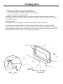
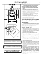
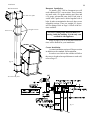
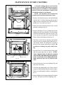
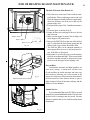
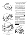
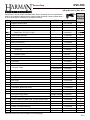
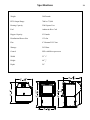
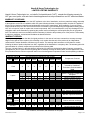
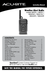
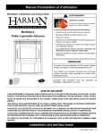
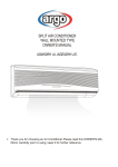
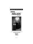
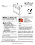
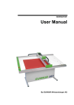
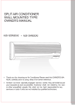
Installation & Operating Manual
The Harman DVC-500 Coal Stoker
R15
SAFETY NOTICE
Please read this entire manual before you install and use your new room heater. Failure
to follow instructions may result in property damage, bodily injury, or even death.
SUITABLE FOR INSTALLATION IN MOBILE HOMES.
IF THIS HARMAN STOVE IS NOT PROPERLY INSTALLED, A HOUSE FIRE MAY RESULT. FOR YOUR SAFETY,
FOLLOW INSTALLATION DIRECTIONS.
CONTACT LOCAL BUILDING OR FIRE OFFICIALS ABOUT RESTRICTIONS AND INSTALLATION INSPECTION
REQUIREMENTS IN YOUR AREA.
Contact your local authority (such as municipal building department, fire department, fire
prevention bureau, etc.) to determine the need for a permit.
do not use makeshift components or other compromises during installation or service.
save these instructions.
R1
#3-90-08311
2
LISTED SOLID FUEL BURNING ROOM
HEATER - MODEL: “DVC 500”
Serial Number:
WHI-
W/N 03625
TESTED TO: ASTM E1509, and parts of UL127
TEST DATE: July, 1996
APPROVED FOR USE IN MANUFACTURED HOMES.
DO NOT REMOVE THIS LABEL.
pREVENT HOUSE FIRES: kEEP DOORS AND HOPPER LID CLOSED DURINg OPERATION.
INSTALL AND USE ONLy IN ACCORDANCE wITH MANUFACTURER’S INSTALLATION AND OPERATINg
INSTRUCTIONS. CONTACT LOCAL bUILDINg OR FIRE OFFICIALS AbOUT RESTRICTIONS &
INSTALLATION INSPECTION REqUIREMENTS IN yOUR AREA. SEE THE INSTALLATION MANUAL
AND CHECk wITH yOUR LOCAL CODES FOR SPECIAL INSTRUCTIONS wHEN PASSINg THE VENT
THROUgH A COMbUSTIbLE wALL OR CEILINg.
UNIT MUST bE PLACED ON A NON-COMbUSTIbLE FLOOR OR FLOOR PROTECTOR ExTENDINg 16”
TO THE FRONT, 8” TO THE SIDES AND 3” TO THE REAR. MINIMUM 24 gA SHEET METAL.
DIRECT-VENT - USE ONLy HARMAN DVC-VENTINg COMPONENTS FROM THE APPLIANCE
THROUgH THE OUTSIDE wALL. USE ONLy 4” TyPE L OR PL PELLET
VENT ON THE OUTSIDE OF HOME.
DO NOT CONNECT TO A CHIMNEy. DO NOT CONNECT THIS UNIT
TO A CHIMNEy OR FLUE SERVING ANOTHER AppLIANCE.
FUEL: ANTHRACITE RICE COAL ONLy. THE EPA PROHIbITS THE
USE OF ANy OTHER FUEL, ExCEPT FOR COAL IgNITION.
INpUT RATING: 6 POUNDS PER HOUR.
4”
Pellet
Vent
ELECTRICAL RATING: 2.5 AMPS, 120 VOLTS, 60 HERTz.
REPLACE gLASS wITH ONLy 5 MM CERAMIC.
Harman Venting
Components Only.
INSpECT AND CLEAN ExHAUST VENTING SySTEM
FREqUENTLy.
MINIMUM CLEARANCES TO
COMBUSTIBLES:
UNIT TO SIDE WALL 18”
UNIT TO REAR WALL 3”
STOVE TOp TO CEILING - 24”
CORNER INSTALLATION - 9”
FLOOR pROTECTION:
FRONT - 16”
SIDES 8”
REAR 3”
9”
46”
18”
8”
8”
9”
16”
42”
Date of Manufacture:
2010 2011 2012 JAN FEB MAR APR MAY JUN JUL AUG SEP OCT NOV DEC
Manufactured by: Harman Home Heating 352 Mountain House Road, Halifax PA 17032
# 3-90-08210
5.5” x 7.5” adhesive
backed
metal
This
appliance
is alsolabel.
approved
for installation into a shop.
3
INDEX
Warnings
4
5
Assembly
6
Installation
7
DVC500 Microprocessor Control
15
Introduction
Operation
17
Maintenance
19
Fuel
23
Wiring Diagram
25
Control and Safety Sensors
26
Parts
27
Specifications
30
Troubleshooting
31
Please read this entire manual before you install and use your new
room heater. Failure to follow instructions may result in
property damage, bodily injury, or even death.
SUITABLE FOR MOBILE HOME INSTALLATIONS.
SAVE THESE INSTRUCTIONS
Harman Home Heating
352 Mountain House Road
Halifax, PA 17032
harmanstoves.com
WARNINGS
4
Carbon Monoxide (CO) Awareness
Carbon monoxide, referred to as CO, is a
colorless, odorless gas that is produced during
combustion of coal and other fuels. CO fumes
are toxic and can be fatal.
The DVC 500 is a closed loop system specially designed to prevent the escape of CO and
other combustion products from the stove.
Even though this stove is designed to be as
safe as possible, it is important that you install
a CO detector. This is true for oil, gas, or wood
burning products as well.
CO detectors are very sensitive and may
sound an alarm for fumes other than CO or CO
from sources other than the stove such as car
or lawn mower exhaust.
If the alarm sounds
1. Increase ventilation by opening windows
or doors.
2. Make sure the stove doors and hopper lid
are closed and latched.
3. Check stove for electrical power and normal
operation.
4. Check for false alarm.
(Never sleep in the same room with any coal burning stove.)
Wet Coal
Freshly delivered coal is watered down to eliminate dust when loading and unloading. Wet rice
coal does not flow as well as damp or dry coal.
We do not recommend burning wet coal; however, we realize if it's the only coal you have,
it is better to burn it than be cold. If you must
burn wet coal, the feed rate must be increased
in order to get the same size fire. As the wet
coal in the hopper dries out, the feed rate must
be decreased. Loading wet coal once or twice a
year will not damage your stove as long as it is
hot and burning. The damage is caused when the
hopper has wet coal in it when the stove is cold.
This will cause rust and corrosion and it is totally
the operator’s fault. Usually after the coal dries
for three or four days, depending on conditions,
it will flow very well and feed properly. Feed
rate will be the same as with dry coal.
Always Empty Hopper
Always empty the hopper when not burning
for more than a week. When left standing
for long periods with wet coal, the pusher
block will rust and corrode, causing it to
seize. If the stoker is then turned "on",
damage to the pusher assembly and feed
motor could result. This will be considered
neglect and will void the warranty on those
parts. Always check to see that moving
parts are free before using, if the unit has
not been burned for a period of time. This
can best be determined by watching the
cam block and pusher arm inside the right
rear side door.
Never use gasoline, gasoline-type lantern fuel, kerosene, charcoal lighter fluid, or similar liquids to start or “freshen up” a fire in this heater. Keep all such liquids well away from the heater
while it is in use.
INTRODUCTION
5
This remarkable design by Harman features the
Verti-flow Direct Vent Stoker System.
This unique, high efficiency unit uses only
outside air for combustion.
Micro-processor controls provide for an automatic wide range of heat output from 7,000 to
75,000 BTU .
With a big 93 pound hopper capacity, this unit
can burn on high approximately 16 hours or extend
for over 96 hours on low.
A Room Sensor connected to the micro-processor automatically adjusts the feed rate to compensate
for changes in temperature.
The ash pan is large enough to hold the ash
from one hopper full of coal at any setting.
The DVC 500 is the most advanced coal
stove ever put into production. However, there
are places where it should not be installed. If the
end of the flue pipe is:
1. Less than 8 feet from an air intake.
2. On the side of the house where a window is
left open for sleeping.
3. Less than 5 feet from a door.
4. Less than 7 feet above and 3 feet away from a
public walkway.
5. Less than 3 feet above ground level.
6. Between two buildings less than 10 feet apart.
It is recommended that the end of the flue
pipe terminates at least 12 inches away from the
side of the building in order to minimize any fly
ash build-up.
Mobile home installations should be done in
accordance with the Manufactured Home and
Safety Standard (HUD), CFR 3280, Part 24.
DAMP COAL SHOULD NOT BE
LEFT IN THE HOPPER OF A COLD
STOVE.
Assembly
1. Install the hopper latch as shown at left.
2. Install 3 firebricks on the cast iron angle behind
the grate as shown.
3. Cement in grates as shown below. This may
already be done at the factory.
3 Bricks
Grate
Inserts
fig. 3
6
Viewing glass
7
The glass in your Harman stove is a special ceramic glass.
• Do not abuse the glass by striking or slamming the door.
• Never burn the appliance if the door glass is cracked or broken.
• Replace only with Harman supplied glass.
Soot and/or fly-ash may accumulate on the viewing glass, and will ocassionally need to be cleaned.
Clean the glass with a soft cloth and mild glass cleaner. Do not spray cleaner on hot glass, and avoid the
use of abrasive cleaners.
Glass replacement
Carefully remove all remaining glass and gasket materials prior to replacing the glass.
Lay the door face down on a flat surface. Remove the glass retainers and screws. Apply the gasket
material to the face of the new glass. Lay the glass into the door, making sure that the glass is contained
within the channels and raised areas of the door itself. Lay the glass retainers into position and install the
screws. Tighten each screw evenly to avoid making any stress points.
HINGE PINS
DOOR
BRASS HANDLE
GLASS
PAW BOLT
HANDLE BOLT
GLASS GASKET
SET SCREW
WOOD HANDLE
4 GLASS RETAINER CLIPS
4 GLASS
RETAINER
BOLTS
INSTALLATION
Tips On Installation
Before the positioning of the unit can be decided a few questions should be considered?
1. Can the unit be vented properly and installed
safely?
2. Will exhaust be vented where fumes can build
up or be drawn into lower levels of the structure
3. Will fumes and fly ash affect the exterior of the
structure or surrounding structures?
4. Are there any local regulations governing the
use and placement of the unit?
5. Are there any structural reasons why the unit
cannot be placed where you want?
6. How close is the electrical outlet?
fig. 6
Follow the guidelines to the left regarding
clearances to combustible materials.
Floor Protector
This stove should be placed on a non-combustible floor protector extending 16 inches to the front,
8 inches to the sides, and 1 inch to the rear.
Straight Through Wall
fig. 7
DO NOT INSTALL A FLUE DAMPER IN THE
EXHAUST VENTING SYSTEM OF THIS UNIT
DO NOT CONNECT THIS UNIT TO A CHIMNEY FLUE SERVING ANOTHER APPLIANCE.
INSTALL VENT AT CLEARANCES SPECIFIED BY THE MANUFACTURER
1. When positioning of the unit has been decided,
use measurements on Page 10 for cutting the hole
through the wall. Don’t forget to figure the thickness of the floor protector used.
2. Cut at least a 9" x 9" hole through the wall.
3. Remove the side doors / rear cover assembly
(6 black screws, 5/16" socket or straight screwdriver)
4. Place the unit in front of the hole approximately
1/2" closer to the wall than the length of the wall
termination. (From outside of wall to back of unit
where termination bolts up)
5. Take the wall termination outside and slide it into
the hole until it mates to the rear of the unit. Go
inside and install the bolts and tighten, making
sure the gasket is in place and the flue pipe section is level.
6. Reposition the unit inward until the stainless steel
intake section comes against the outside wall
surface. NOTE: If the wall is over 8" thick you
will need a longer wall termination. The standard
termination will provide 3" of wall clearance
behind the stove, with a 8" wall. Therefore, with
a 5" thick wall, it will provide 6" of clearance
behind the stove.
8
Installation
WARNING:
DO NOT INSTALL IN MOBILE
HOME SLEEPING ROOM
CAUTION:
THE STRUCTURAL INTEGRITY OF THE
MOBILE HOME FLOOR, WALL, AND
CEILING/ROOF MUST BE MAINTAINED.
9
7. Check the exterior of the termination for best fit
and screw to exterior and caulk with high grade
exterior caulking.
8. Complete any other exterior flue piping necessary, using 4" pellet venting.
9. Back inside, place the 2 halves of the interior
wall trim plate over flue pipe. Using the black
pop rivets, fasten together, then slide it against
the wall and fasten it to the wall.
10. Replace the side door / rear cover assembly
with 6 black screws.
11. Complete the unit assembly and test.
Wall Trim Plate
Gasket
Wall
Termiation
Standard Wall
Termination
Wall Trim Plate
fig. 9
Open
fig. 8
Installation
10
Installation
11
Basement Installation
To install a DVC 500 in a basement you will
need additional DVC vent sections. These sections
are made with a 316-grade stainless steel liner and
a 20 gauge galvaneeled outer shell. Each joint is
sealed with a gasket and is bolted together with 4
bolts. In order to maintain the best seal, there are no
adjustable sections. There are straight, 45 degree,
and Tee fittings. Refer to Page 14 for all of the sections available.
Wall Termination
Tee with cover plate
Joint covers
Straight sections
Never use venting other than Harman DVC
venting inside the building. It is the only vent
certified for this appliance.
Refer to page 12 & 14 to calculate which sections will be needed for your installation.
Corner Installation
A corner installation requires a 45 degree section
in addition to the standard wall termination.
In order to cut a hole in the wall that will allow
the stove to be placed an equal distance to each wall,
refer to Page 13.
fig. 10
Tee with cover plate
D
fig. 11
Installation
12
Installation
13
Installation
Harman Direct Vent Coal Flue Pipe Venting System
1" Clearance to Combustibles
Exterior Termination for wall
thickness up to 8 inches
9-5/8"
Gasket
45°
12"
1-10-08314
1-10-08313
3-44-06256
1-10-08310
"T"
13"
9"
6"
1-10-08315
8-3/4"
1-10-08317
1-10-08321
Joint Cover
8"
12"
1-10-08316
47"
1-10-08320
37"
11"
1-10-08326
27"
1-10-08319
10"
1-10-08324
Exterior Termination for wall
thickness up to 16 inches
1-10-08323
1-10-08322
Spacer 3/16"
1-10-08318
Exterior Termination for wall
thickness up to 12 inches
20"
1-10-08312
16"
1-10-08325
Maximum Horizontal Run is 48 Inches - (4 ft.)
1-10-08311
14
Operation
ESP CONTROL
Power Light
Indicates power is "on" to
the control.
15
Feed Adjuster
Sets the maximum feed
rate, 1 to 5
Test
Runs all motors at
full speed for two
minutes to check
operation. After
two minutes the
feeder stops and the
distribution blower
alternates from high
to low every four
seconds to remind
you that you are still
in "Test Mode".
Status Light
Will be lit in either Stove
or Room Temp Mode when
pointer is not within "off"
position band except after
normal shut down. Blinks
to indicate errors listed
below.
Ash Removal position
See page 19
Indicates power to
Distribution Blower
Indicates power to
Combustion Blower
Distribution Blower
speed adjustment range.
Indicates power to the
Feed Motor.
Indicates power to the
Draft Motor.
Temp Dial
Allows you to adjust the room temperature
in Room Temp Mode using the outer scale
marked in degrees Fahrenheit. It also allows
you to adjust the stove temperature while
in Stove Temp Mode using the inner scale
marked from 1 to 7.
fig. 12
DDM Port
Allows service technician to
attach diagnostic meter when
troubleshooting or verifying
proper operation.
Mode Selector
Allows you to choose between Room Temp
Mode, Stove Temp Mode, or OFF. Also
allows you to vary the Distribution Blower
speed by turning the knob to the "high" or
"low" side of each mode.
Status Light Error Messages:
2 Blinks: Indicates that there is insufficient negative
pressure in the firebox. This begins a shut-down process
described in more detail on Page 31.
The most common cause of the 2 blink status is leaving the
ash door open without turning the Feed Adjuster to "Ash
Out". For other causes of a 2 blink status see Page 32.
This requires a Manual Reset*.
3 Blinks: Indicates that the ESP (Exhaust Sensing Probe)
has gone out of range a specified number of times. If
the stove seems to be performing normally, perform a
Manual Reset*.
4 Blinks: Can occur only in Room Temp Mode and indicates Room Sensing Probe has failed or is not installed.
If a Room Sensing Probe is then installed, the status light
will automatically reset.
5 Blinks: Indicates a lack of communication between the
circuit board and the TCP (Temperature Control Probe).
This requires a manual reset*.
* Manual Reset: Disconnect power cord for a few seconds
and reconnect. If error still occurs call your Dealer.
16
Hopper Lid Latch
ESP Control
Glass Door
Latch Handle
Side Panel Latch
Ash Door
Latch Handle
Operation
Testing Operation:
Turn the Feed Adjuster to "Test" mode, (fig.
13.) This will cause all motors to run 100% for 2
minutes. The lights on the control panel will be lit
for each motor. If you leave it on "test" the blowers
will cycle as an audible reminder.
fig. 13
Starting Fire:
1. Fill the hopper with dry coal. NOTE: Remove
all coal from hopper ledge. (fig 17)
2. Fill burn-grate area from firebrick to front of
grate with about one inch of (DRY) coal.
3. Plug into 120 volt AC outlet and turn control to
"OFF". Turning to "OFF" and then back to the
desired mode resets the control.
4.Turn Feed Adjuster to the # 3 position, fig. 14.
5. Make a valley in the coal at the top of the burn
grate. Fill valley with fire starting material (coal
starter, crushed charcoal, wood pellets).
6.Turn Mode Selector to Room Temp or Stove
Temp as desired.
7. Turn the Temp Dial to the desired setting.
8. Light the fire and make sure that all doors and
the hopper lid are closed. As the ESP senses the
correct temperature, the Feed Motor will start.
Test Position
fig. 14
#3 Feed Adjustment setting
5
1
2
Shutdown Procedure:
To kill the fire or stop burning the stove, turn
the Mode Selector knob to the "OFF" position. This
will stop the feeder and the fire will burn out. When
the stove cools to about 95 degrees Fahrenheit, all
motors will stop. The unit can then be unplugged.
NOTE: It is always best to let the stove run out of
coal to shut it down rather than use the "OFF"
position. This is because there is no moisture
left in the hopper from the coal. Always run the
stove out of coal to shut it down when the heating
season is over or if the stove will not be used for
several days.
Restarting Fire After Shutdown:
All ash and partially burned coal must be cleaned
out from behind grates down under firebrick until
fresh coal is seen. Follow "Starting Fire" procedure
above.
fig. 15
17
Operation
Fig. 16
18
Keep coal off
ledges
Fig 17
When to use "Stove Temp Mode"
This setting will produce medium heat with the Distribution Blower on "low".
In "Stove Temp Mode" the control will regulate
the fire to match a constant exhaust temperature,
based on the #1 thru 7 settings on the inner portion
of the temp dial. Heat output and fuel consumption
will remain constant. This makes it possible to tell
how long a hopper full of coal will last. The distribution blower speed can be varied according to the
position of the mode selector, between "low" and
"high", fig. 16.
When to use "Room Temp Mode"
This setting will produce a room temperature of 70 degrees with the Distribution Blower at "medium" speed.
This setting will produce continuous maximum heat output
with the Distribution Blower at full speed.
In "Room Temp Mode" heat output is controlled
automatically by use of the Room Sensing Probe.
When the Room Sensing Probe calls for heat, the
stove will increase output. When the Room Sensing Probe is getting close to the set temperature,
the stove will begin to level off output and keep the
fire burning at just the right temperature to maintain
that setting. If the temperature in the room exceeds
the set point, the stove will idle on a low burn until
more heat is needed.
High output is determined by the Feed Rate.
The maximum Feed Rate should be set for 1 1/2" to
2" of ash in front of the fire.
In "Room Temp Mode" fuel consumption is
sacrificed for exact room temperature. Therefore,
as it gets colder, more coal will be burned automatically.
The distribution blower speed can be varied
according to the position of the mode selector.
DAILY MAINTENANCE
Fig. 18
Ash Out Position
If the feed adjuster is left in
the "Ash Out" position the
fire will burn out.
Ash Removal
With each hopper of coal that is burned, approximately one ashpan full of ashes must be removed.
(fig. 19) It may take from one to four days for the ash
pan to get full, depending on the burn rate.
Failure to remove the ashes will result in a
blocked grate and the fire will not burn properly.
Remember, the ashpan will be hot, so always wear
protective gloves.
Ash Removal Setting:
The "Ash Out" position on the feed adjuster knob
is for ash removal (fig. 18). This position stops the
Combustion Blower, the Feeder Motor, and slows the
Distribution Blower so the doors can be opened. This
is to limit exhaust fumes from leaving the unit.
Don't forget to turn knob back to previous feed
number setting after completion of ash removal.
Removing Ash While Unit Is Burning:
WARNING
OPENING THE VIEWING DOOR OR
ASH DOOR WITHOUT TURNING THE
FEED ADJUSTER TO THE "ASH OUT"
POSITION MAY CAUSE COMBUSTION
GASES AND FLY ASH TO ESCAPE.
fig. 19
CAUTION: Ash pan handle will be hot,
wear gloves.
Make note of the position of the Feed Adjuster
knob so it can be returned to the same position when
you are finished removing the ashes.
Turn the Feed Adjuster knob to "Ash Out",
this is the ash removal setting, Fig 18. This setting
turns off the Combustion Blower and Feeder Motor
but does not turn off Draft Motor. Now the ash door
can be opened with minimal exhaust leakage. If ash
removal takes more than 4 minutes, the Distribution
Blower will start to cycle up and down to indicate
the Feed Adjuster knob was left in the "Ash Out"
position. This is not a problem if you remember to
return the Feed Adjuster to its previous setting when
completed. If left in the "Ash Out" position, the
fire will burn out.
Ashes should be placed in a metal container with a tight fitting lid. The closed container of ashes should be placed on a
noncombustible floor or on the ground, well away from all
combustible materials, pending final disposal. If ashes are
disposed of by burial in soil or otherwise locally dispersed,
they should be retained in the closed container until all cinders
have thoroughly cooled.
19
WEEKLY MAINTENANCE
Empty Fines Tray
The small Fines Tray in the side of the stoker
should be removed and emptied
To remove the Fines Tray, first open the door
on the left rear of the stove. Next, loosen the thumb
screws holding the Fines Tray Cover, fig# 20. Next,
turn the cover 90 degrees and slide out the Tray as
shown. If the Tray has over- flowed, use a vacuum
cleaner to reach into the opening and remove the
excess material.
Cleaning Glass While Unit Is Burning:
Caution: The glass and door frame will be
hot, gloves must be worn.
Turn the temperature control to lowest setting
and allow the stove to cool down. Have all cleaning
supplies ready and close by. Take note at which # the
Feed Adjuster is set, fig 14. Turn Feed Adjuster knob
to "Ash Out". (This is the ash removal setting.) This
setting turns "off" the Combustion Blower and Feeder
Motor but does not turn "off" the Draft Motor. Now
the viewing door can be opened with minimal exhaust
leakage. Use a safety razor in handle and scrape the
inside of the glass with the blade almost flat to the
surface, Fig 21. If further cleaning is necessary, the
window can now be cleaned with liquid cleaner and
a non synthetic cloth. CAUTION: Do not spray
cleaner directly on Hot Glass. If the cleaning takes
more than 4 minutes, the Distribution Blower will start
to cycle up and down to indicate the Feed Adjuster
knob was left in the "Ash Out" (ash removal setting).
This is not a problem, just remember to return the
Feed Adjuster to its previous setting when completed.
FINES TRAY COVER
FINES TRAY
Fig 20
Fig 21
Soot and Fly Ash
The products of combustion will contain small
particles of fly ash. The fly ash will collect in the
exhaust venting system and restrict the flow of the
flue gases. Incomplete combustion, such as occurs
during startup, shutdown, or incorrect operation of
the room heater, will lead to some soot formation
which will collect in the exhaust venting system.
The exhaust venting system should be inspected
at least once every year to determine if cleaning is
necessary.
20
MAINTENANCE: EVERY 3 MONTHS:
Never Block Air Outlets on top of stove, above door.
A 3-month cleaning will give you a base line
as to how often your DVC500 needs to be cleaned.
Cleaning intervals will differ in each installation
because of the ash and moisture content of the
coal and the amount of coal burned.
NOTE: Unit should be off & cooled down
enough to perform these maintenance items:
1.Remove Ash Pan then remove ash shield behind
Ash Pan, fig.22. Lift the shield up and forward in
order to remove it from the stove. This will expose
the Blower Cover and Latch, fig.23.
Tabs
Ash Shield
2.Rotate the Latch counterclockwise to the vertical
position as shown in fig. 24.
3. Remove the Blower Cover by tilting the left side
slightly forward. Next, slide the Cover left and out
of the slot that holds the right side in place. The
Cover can now be removed to expose the Draft
Blower Wheel and Exhaust Outlet, fig. 25.
Fig 22
4. The blower wheel, blower housing, and exhaust
outlet can now be cleaned with a brush and vacuum cleaner. NOTE: The ESP probe is located at
the rear of the exhaust outlet shown in fig 28. Be
careful not to damage the probe when cleaning.
Latch
Fig 23
Blower Cover
5.Open the Fines Cover on the bottom of the feeder
under the grates and clean, see fig.26. ATTENTION: MAKE SURE COVER IS CLOSED
AND TIGHTENED BEFORE RELIGHTING
UNIT. UNIT WILL NOT OPERATE PROPERLY WITH CLEAN OUT COVER LEAKAGE.
6.Check the flue pipe for excess buildup of fly ash
and clean if necessary.
7.Clean the glass thoroughly, use a safety razor to
scrape the sulfur buildup from the surface of glass.
Then clean with standard window cleaning fluid,
fig.21.
Rotate Latch
Fig 24
8.Inspect all gaskets for damage and turn the control
to "test", for motor test before relighting a fire.
21
END OF HEATING SEASON MAINTENANCE:
The End Of Season Shut Down List.
1. Allow the stove to run out of coal in order to extinguish the fire. This saves having to remove the coal
from the hopper manually and most importantly,
drives the moisture out of the stove that may be
present in the coal.
2. Perform all the steps of the 3 month maintenance
list.
3. Clean the glass as shown in fig.21.
4. Empty the fines tray and inspect the area for rust
and corrosion
5. Make sure the hopper is empty. Wet or damp coal
in the hopper will promote rust.
6. Remove the FSS Tube from the rear of the firebox
(fig.27) and clean the brass fitting going into the
firebox with a pipe cleaner. Reconnect tube.
7. The FSS line filter can be changed annually to
insure proper flow, however, it may only be necessary if the filter is discolored.
8. Remember to cover the flue pipe over the summer
to block out rodents and birds. Place a note inside
the unit to remind yourself or others not to forget
to uncover the flue pipe before lighting a fire.
Exhaust Outlet
Blower Wheel
Blower Cover
Fig. 25
fig. 26
GRATE CLEAN-OUT COVER
Prevent Rust
Summertime moisture and high humidity are
your stove's enemy. A clean stove will have less
fly ash and fines to absorb moisture and cause rust
and corrosion. Allowing wet coal to remain in the
hopper of a cold stove will promote the formation of
rust and corrosion. Some owners choose to spray a
light coating of oil on all internal workings and the
firebox as a rust inhibitor.
Annual Service
It is recommended that your DVC500 is serviced
annually by your trained Harman dealer. The best time
for this service is during a non-use period. You may
choose to combine this service with the end of season
maintenance.
FSS Tube
FSS Line
Filter
Fig. 27
22
Motors
23
Feed Motor
3-20-60906
Combustion
Blower
1-10-08332
Distribution
Blower
3-21-22647
Draft Motor
3-21-08639
Fig. 28
Fuel
The DVC500 is designed to burn Anthracite
Rice Coal, which is approximately 3/8" long and
wide by 3/16 thick. Anthracite coal is considered
either White Ash or Red Ash.
White Ash Coal will have 13 to 14,000 btu's
per lb. White ash coal usually has less ash and will
burn longer.
Red Ash coal is usually about 12,000 btu's per lb.
and is higher in volatiles. Higher volatiles makes the
coal easier to light and produces a more yellow flame.
At a very low burn rate the TCP (Temperature
Control Probe) may be activated with Red Ash coal,
especially if the hopper lid is open or leaking. The
TCP senses the temperature of the feeder and feeds
coal if the temperature rises too much. This prevents
the fire from reaching the coal in the hopper. Red Ash
Coal may form klinkers (fused together ash) which
may cause grate blockage in severe cases.
ESP Probe
3-20-00744
Anthracite Coal can be purchased in bags or in
bulk. If you buy in bulk, try to have the coal delivered
before temperatures reach the freezing level. This is
because salt may be added to the coal to keep it from
freezing on the truck. This will not affect burning but
will promote rust and corrosion.
Some Coal Companies wash their coal better
than others to remove fines and dirt. This makes air
flow through the coal better and produces less fly ash.
Whether bagged or in bulk, the coal must be
dry before loading it into the stove. At a minimum,
open bags a few days in advance to allow drying.
Buy your bulk coal mid summer to allow plenty of
time for drying.
Good, clean, White Ash Coal is the fuel of
choice, "however" Red Ash Coal will also burn well.
As long as it is Anthracite.
24
Grate System Assembly Or Replacement:
grate insert
Fig. 29
Fig.30
grate angle
grate holder
The DVC500 grate system is composed
of four pieces: the grate holder, (2)-63 hole
grate inserts, and grate angle. The grate angle
is bolted to the grate holder with (2) 3/8 x 1 1/4
bolts. Before installing the grate holder, 3/8"
round gasket must be checked in the groove on
the bottom side of the grate holder, as shown
in Fig 31. Check to be sure the gasket has not
been damaged.
The grate holder must be installed through
the top door opening after the feeder has been
installed.
Fig.31
bottom groove
Fig.32
Locate the flange at the rear of the grate
holder into the slot on the feeder as shown
below. Bolt the front end down with the 1/4 x
20 allen bolt and nut provided. The rear end
will be locked in place by the flange. Before
tightening the bolt, be sure the grate holder is
back as far as possible and centered side to side
on the feeder opening.
Install grate inserts as shown at left. Seal
joints with high temp furnace cement caulking as
shown in Fig 30. Insert first grate and squeeze
into caulking. Caulk other grate insert, Fig 29,
on edge that joins grate already in place. Insert
caulked grate in remaining space and squeeze
together to make middle joint as tight as possible. Clean any caulking that has pushed out
from the joints on top of grates. Let caulking
cure before firing.
Install firebricks
as shown
Fig.33
gasket
IMPORTANT
Be sure the grate holder is centered and back
as far as possible.
Maintenance Schedule
25
It is recommended that End of Season Cleaning and the Annual Service are coordinated to happen at the
same time for best results.
Wiring Diagram
HARMAN DIRECT VENT COAL STOKER( DVC 500 C ) WIRING DIAGRAM
(RED TWISTED)
ESP
CONTROL
BOARD
TO ROOM SENSOR
BLACK
SPLICE
3
4
5
6
78
9
10
11
GREEN
GROUND
WHITE
BLACK
RED
WHITE
BLUE
WHITE
GREEN
GREEN
X
1-10-163
ORANGE
WHITE
TCP
Stove
YELLOW&WHITE
FSS 1-10-163
FIREBOX STATIC
SENSOR
DISTRIBUTION BLOWER
BLACK
BLACK
WIRE CONNECTORS
18-3 RUBBER CORD
COMBUSTION BLOWER
BLACK
BLACK
PART NO. 3-89-08193 Rev A
BLACK
WHITE
GREEN
BLACK
WHITE
GREEN
18-3 RUBBER CORD
FEEDER MOTOR
BLUE&BLACK
MALE / FEMALE
DRAFT MOTOR
TCP PROBE
1
WHITE
POWER CORD
(RED TWISTED)
YELLOW TAPE ON ENDS
FUSE
ROOM
SENSOR
ESP PROBE
300 WATTS -- 2.5 A. --
120 VOLTS A.C. 60 HZ.
26
Control and Safety Sensors
ESP
The ESP (Exhaust Sensing Probe) is a temperature
sensing probe located in the exhaust outlet. The ESP
works with the Control to perform all burn rate functions as well as high and low limit control.
ESP
X
1-10-163
TCP
Stove
FSS 1-10-163
FIREBOX STATIC
SENSOR
This sensor is located in the control box behind
the control board. It is preset and is non-adjustable.
TCP
Room Sensor
The Room Sensor is a small temperature sensor placed
where you would normally put a thermostat. The
Room Sensor is extended to the stove with normal
thermostat wire. The Room Sensor works with the
ESP and the Control to provide the right size fire.
FSS
The FSS (Firebox Static Sensor) is an electronic
pressure sensor reading the firebox pressure. The
FSS works with the ESP Control to adjust the draft
blower speed to compensate for wind and changing
house pressures.
TCP
The TCP (Temperature Control Probe) is located
on the left side of the feeder. The TCP works with
the Control to reduce the feeder temperature if the
temperature begins to rise.
dvC-500
Service Parts
beginning manufacturing date: N/A
Ending manufacturing date: Active
direct vent Coal Stoker
1-70-08600-1 (black), 1-90-08600-1 (black w/door)
1
2
3
4
5
6
7
8
9
10
14
13
11
12
Part number list on following page.
02/11
dvC-500
Service Parts
beginning manufacturing date: N/A
Ending manufacturing date: Active
IMPORTANT: THIS IS DATED INFORMATION. When requesting service or replacement
parts for your appliance please provide model number and serial number. All parts listed
in this manual may be ordered from an authorized dealer.
ITEm
dESCrIPTION
COmmENTS
Stocked
at depot
PArT NumbEr
1
Hopper Lid Swell Latch
3-31-191410
2
Hopper Lid Assembly
1-10-08212A
3
Door Kit Assembly
Door Kit Assembly (Gold)
Classic Black
No longer available
Glass, Rect 12-7/16” X 17-5/8”
1-00-08600-1
1-00-08600-4
3-40-08214
Y
1-10-01000
Y
4
Grate Holder Assembly
5
Grate Inserts
6
Wooden Handle with screws
1-00-00122
7
Ash Door Assembly
1-10-08205A
Qty. 2 Req.
Ash door Latch Hardware
8
Y
4-00-08307D
1-00-38223
Y
Y
Control Box Assembly - W/Board & Pressure Switch
Control Box
1-10-06486
Circuit Board (Requires D-Shaft Knobs)
1-00-05889
Y
Pressure Switch
1-00-163
Y
9
Hopper Assembly
1-10-08207A
10
Combustion Blower - W/Flange
1-10-70219720
Y
11
Draft Motor
3-21-08639
Y
12
Distribution Blower
3-21-22647
Y
13
Thermister Probe
Pre 008065076
1-00-00744
Y
Post 008065076
3-20-00844
Y
14
Feed Motor - 4 rpm
3-20-60906
Y
3-30-6007-25
Y
1/4”-20 x 2 1/2” Phillips Round Head Zinc Pltd Machine Screw
Pkg of 25
Ash Lip Trim
3-43-4722386
Ash Pan
1-10-08177
Y
Ash Shield
2-00-06423B
Y
Brass Elbow
3-40-00121
Brick Set
1-00-00382
Combustion Blower Inlet Cover
1-10-08552W
Combustion Blower Seal
3-44-06417
Y
Combustion Inlet Cover Retainer Assembly
1-10-08553S
Y
Door (frame only) (Gold)
Door (frame only)
No longer available
Cast
Y
1-10-05165
4-00-05165
Double Paddle Fan Blade 4-3/4” (old tilt out draft motor)
3-20-502222
Y
Double Paddle Fan Blade 5” (new style draft motor)
3-20-502221
Y
Feeder Assembly
1-10-08197A
Feeder Cam Block Assembly
1-10-00102A
Filter, In line for DVC
3-40-35125
Fine Tray
2-00-06387S
Y
Additional service part numbers appear on following page.
02/11
dvC-500
Service Parts
beginning manufacturing date: N/A
Ending manufacturing date: Active
IMPORTANT: THIS IS DATED INFORMATION. When requesting service or replacement
parts for your appliance please provide model number and serial number. All parts listed
in this manual may be ordered from an authorized dealer.
ITEm
dESCrIPTION
COmmENTS
Gasket, Flue Pipe
Pkg of 3
Stocked
at depot
PArT NumbEr
3-44-06256-3
Y
Gasket, Glass, 1/4” Round
1-00-2312
Y
Gasket, Hinge Seal
2-00-06416
Y
Gasket, Hopper Lid
3-44-06415
Y
Gasket, Round 1/2” (Load Door)
20 Ft
1-00-1086204
Y
Glass Clip
Pkg of 4
2-00-05202-4
Y
#10-24 x 3/8” Alloy Steel Black Oxide Button Head Cap Screw
Pkg of 100
3-30-3011-100
Y
Gold Air Grill Trim
3-43-08157
Handle Assembly
1-00-08176
Hercules Grate Cement
12 oz. Tube
Y
3-42-08308
Paw Bolt
4-31-08055
Y
Pillow block Bearing
3-31-06238
Y
Pusher Block, Aluminum
3-50-06438
Y
Room Sensor
3-20-00906
Y
Silicone foam 1/16” - grey (hopper lid)
3-44-08551
Y
Silicone Tubing For In Line Filter
1-00-5113574
Y
Silicone, Red Sponge W/PSA (Old Units)
3-44-08215
Y
Pre 008065076
3-20-08272
Y
Post 008065076
3-20-00844
Y
Qty. 2 Req.
2-00-06326
TCP Probe (Yellow Thermister Probe)
Termination Trim Collar
Tile frame assembly 12 X 6
No longer available
Tilit Draft Motor
1-00-08617
3-21-42940
Y
Tile Pack
Brushed Stainless Steel Plate 12 X 6
Ceramic Tile 12 X 6 (No longer available)
Slate Tile 12 X 6
Deer
1-00-06732-2
Pheasants
3-43-120601
Deer
3-43-120602
Mallards
3-43-120603
Old Mill
3-43-120604
Cottage
3-43-120605
Eagle
3-43-120606
Bridge
3-43-120607
Bear
3-43-120608
Lighthouse
3-43-120609
Trout
3-43-120610
Floral
3-43-06731-11
Horse Riders
3-43-06731-12
Deer
3-43-06731-2
Lighthouse
3-43-06731-9
02/11
Specifications
Weight
500 Pounds
BTU Output Range
7000 to 75,000
Heating Capacity
2200 Square Feet
Fuel
Anthracite Rice Coal
Hopper Capacity
93 Pounds
Distribution Blower Size
135 cfm
Flue
4" Harman DVC Vent
Wattage
295 Watts
Control ESP with Micro-processor
Width
25 3/4"
Height
40 3/4"
Depth
29"
30
2 Blink Status Details:
DVC 500-C
Firebox Static Pressure
Safety Protocol
After 72 minutes, if the safety switch has not sensed
another pressure loss, the unit will automatically go
back up to Stage 1.
The status light will continue to blink (2 blinks)
The DVC-500 operates with a negative pressure
throughout Stage 1 and Stage 2.
firebox as a safety feature. The control continuously
If the safety switch senses a loss of negative presadjusts the draft motor speed to maintain a safe firesure anytime during the Stage 2 Protocol, the unit
box negative static.
automatically goes to the Stage 3 Protocol.
NOTE: Observe the intensity of the Draft Motor
Stage 3:
light on the control panel in comparison with the
During stage 2, if another loss of negative pressure
Feed Motor light when it is on. When the appliance
is sensed;
and venting system are clean, the indicator light is
much dimmer than the others. This is because there The status light will continue to blink 2 blinks.
is lower voltage flowing to the draft motor. As ashes The Distribution Blower will be cycling "high" to
build up, the light will get brighter because the draft "low" as an audible warning.
motor needs to run faster in order to maintain the The Combustion Blower and Feeder Motor will
negative pressure in the firebox. When the indicator shut off.
light for the draft motor appears as bright as the rest When the unit reaches Stage 3 these motors will not
of the lights, it is a good indication that it's time to restart.
clean the appliance and the venting.
The Draft Motor will continue to run at maximum
voltage, but the fire will go out.
If the circuit board is flowing full line voltage to the
Draft Motor, and the negative pressure in the firebox [At any time, the 2 blink status can be reset by
is too low, the following safety protocol will begin. disconnecting the power to the unit for a few
seconds.]
Stage 1
When the safety switch senses a loss of negative
pressure in the firebox for more than 68 seconds the
following happens:
The combustion blower will reduce in speed.
During this cool down period the feeder is allowed
to opreate. If needed, the feeder can opreate for up
to 3 minutes.
After 72 minutes, if the safety switch has not sensed
another pressure loss, the unit will automatically go
back to the control board setting.
If the safety switch senses a loss of negative pressure anytime during the STAGE 1 Protocol, the unit
automatically goes to the STAGE 2 Protocol.
Stage 2:
If Stage 1 has already begun and the negative pressure is lost:
The status light will start to blink ( 2 blinks ).
The combustion blower and feeder motor will shut
off. These motors will remain off for a 5 minute cooldown period. After five minutes, those components
will restart at a reduced feed rate ( 30 seconds max.)
for 72 minutes.
CAUTION
Resetting a 2 Blink Status likely indicates
that service is required.
Clean the appliance and the venting system
thoroughly. If the error persists, contact
your dealer for more advanced service.
31
DVC-500 Firebox Static Pressure Safety Protocol
Causes And/Or Reasons For (2-blink) Shutdown:
The DVC-500 operates with a negative pressure 12. Poor or improper flue termination, other than
firebox as a safety feature. Any loss of this negative those shown in the owners manual.
pressure will start the safety protocol, ( A two blink
13. Too high of negative pressure in the area being
status warning )
heated. This is usually caused by the area being too
The following list of potential reasons for warnings tight and using many exhausting appliances ( range
hood, clothing dryer. exhaust fans, etc.). Often this
is in order of most likely to least likely to occur:
1. Opening the viewing door or the ash door for condition can be caused by heavy and gusting winds
long periods of time without turning the feed adjuster hitting the outside, creating a negative pressure inside.
This internal to external pressure difference may
knob to the "ASH OUT" position.
cause the unit to go in and out of Stage 1.
2. Blocked or partially blocked flue pipe. This is
generally a slow buildup and may only cause the unit 14. Faulty computer circuit or disconnected wiring
to go in and out of Stage 1. Although as the condition between control board and safety switch.
worsens, the unit will continue to step down until it
15. Faulty safety switch (not field adjustable).
goes out.
3. Draft motor fan blades dirty. This is generally a 16. Draft motor failure - there is electricity to the
slow buildup and may only cause the unit to go in and motor but it will not turn.
out of Stage 1. Although as the condition worsens, the
[At any time, the 2 blink status can be reset by
unit will Continue to step down until it goes out.
disconnecting the power to the unit for a few
4. Draft motor fan cover plate not installed or not seconds.]
in proper position. (Behind ash pan)
5. Gasketing problems with the viewing or ash
removal door.
6. Grate clean-out cover not closed properly,
Fig.26.
7. Grate inserts are extremely loose or out of alignment, fig. 30.
8. Coal ash building up behind the ash pan to a
point where the ash door is sprung and not sealing
when latched.
9. Transparent tubing from firebox to sensing switch
is off or blocked with fly ash.
10. Poor seal on the hopper lid (usually caused by
coal under hopper lid edge gasketing after fueling).
11. Fines tray cover not closed properly, fig. 20.
32
33
Hearth & Home Technologies Inc.
LIMITED LIFETIME WARRANTY
Hearth & Home Technologies Inc., on behalf of its hearth brands (”HHT”), extends the following warranty for
HHT gas, wood, pellet, coal and electric hearth appliances that are purchased from an HHT authorized dealer.
WARRANTY COVERAGE:
HHT warrants to the original owner of the HHT appliance at the site of installation, and to any transferee taking ownership
of the appliance at the site of installation within two years following the date of original purchase, that the HHT appliance
will be free from defects in materials and workmanship at the time of manufacture. After installation, if covered components manufactured by HHT are found to be defective in materials or workmanship during the applicable warranty period,
HHT will, at its option, repair or replace the covered components. HHT, at its own discretion, may fully discharge all of its
obligations under such warranties by replacing the product itself or refunding the verified purchase price of the product
itself. The maximum amount recoverable under this warranty is limited to the purchase price of the product. This warranty
is subject to conditions, exclusions and limitations as described below.
WARRANTY PERIOD:
Warranty coverage begins on the date of original purchase. In the case of new home construction, warranty coverage
begins on the date of first occupancy of the dwelling or six months after the sale of the product by an independent,
authorized HHT dealer/ distributor, whichever occurs earlier. The warranty shall commence no later than 24 months
following the date of product shipment from HHT, regardless of the installation or occupancy date. The warranty period for
parts and labor for covered components is produced in the following table.
The term “Limited Lifetime” in the table below is defined as: 20 years from the beginning date of warranty coverage for
gas appliances, and 10 years from the beginning date of warranty coverage for wood, pellet, and coal appliances. These
time periods reflect the minimum expected useful lives of the designated components under normal operating conditions.
Warranty Period
Parts
Labor
1 Year
2 years
HHT Manufactured Appliances and Venting
Gas
X
X
Wood
X
X
X
3 years
Pellet
EPA
Wood
Coal
X
X
X
X
X
X
X
X
X
Components Covered
Electric Venting
X
X
All parts and material except as
covered by Conditions,
Exclusions, and Limitations
listed
Igniters, electronic components,
and glass
Factory-installed blowers
Molded refractory panels
X
Firepots and burnpots
5 years
1 year
7 years
3 years
10
years
1 year
X
Limited
3 years
Lifetime
X
X
X
X
X
90 Days
X
X
X
X
X
X
X
X
Castings and baffles
X
X
Manifold tubes,
HHT chimney and termination
Burners, logs and refractory
Firebox and heat exchanger
X
X
All replacement parts
beyond warranty period
See conditions, exclusions, and limitations on next page.
4021-645C 12-29-10
Page 1 of 2
WARRANTY CONDITIONS:
•
•
•
•
34
This warranty only covers HHT appliances that are purchased through an HHT authorized dealer or distributor. A list of
HHT authorized dealers is available on the HHT branded websites.
This warranty is only valid while the HHT appliance remains at the site of original installation.
Contact your installing dealer for warranty service. If the installing dealer is unable to provide necessary parts, contact
the nearest HHT authorized dealer or supplier. Additional service fees may apply if you are seeking warranty service
from a dealer other than the dealer from whom you originally purchased the product.
Check with your dealer in advance for any costs to you when arranging a warranty call. Travel and shipping charges
for parts are not covered by this warranty.
WARRANTY EXCLUSIONS:
This warranty does not cover the following:
• Changes in surface finishes as a result of normal use. As a heating appliance, some changes in color of interior and
exterior surface finishes may occur. This is not a flaw and is not covered under warranty.
• Damage to printed, plated, or enameled surfaces caused by fingerprints, accidents, misuse, scratches, melted items,
or other external sources and residues left on the plated surfaces from the use of abrasive cleaners or polishes.
• Repair or replacement of parts that are subject to normal wear and tear during the warranty period. These parts
include: paint, wood, pellet and coal gaskets, firebricks, grates, flame guides, light bulbs, batteries and the discoloration of glass.
• Minor expansion, contraction, or movement of certain parts causing noise. These conditions are normal and complaints related to this noise are not covered by this warranty.
• Damages resulting from: (1) failure to install, operate, or maintain the appliance in accordance with the installation
instructions, operating instructions, and listing agent identification label furnished with the appliance; (2) failure to
install the appliance in accordance with local building codes; (3) shipping or improper handling; (4) improper operation, abuse, misuse, continued operation with damaged, corroded or failed components, accident, or improperly/
incorrectly performed repairs; (5) environmental conditions, inadequate ventilation, negative pressure, or drafting
caused by tightly sealed constructions, insufficient make-up air supply, or handling devices such as exhaust fans or
forced air furnaces or other such causes; (6) use of fuels other than those specified in the operating instructions; (7)
installation or use of components not supplied with the appliance or any other components not expressly authorized
and approved by HHT; (8) modification of the appliance not expressly authorized and approved by HHT in writing;
and/or (9) interruptions or fluctuations of electrical power supply to the appliance.
• Non-HHT venting components, hearth components or other accessories used in conjunction with the appliance.
• Any part of a pre-existing fireplace system in which an insert or a decorative gas appliance is installed.
• HHT’s obligation under this warranty does not extend to the appliance’s capability to heat the desired space. Information is provided to assist the consumer and the dealer in selecting the proper appliance for the application. Consideration must be given to appliance location and configuration, environmental conditions, insulation and air tightness of
the structure.
This warranty is void if:
•
•
•
The appliance has been over-fired or operated in atmospheres contaminated by chlorine, fluorine, or other damaging
chemicals. Over-firing can be identified by, but not limited to, warped plates or tubes, rust colored cast iron, bubbling,
cracking and discoloration of steel or enamel finishes.
The appliance is subjected to prolonged periods of dampness or condensation.
There is any damage to the appliance or other components due to water or weather damage which is the result of, but
not limited to, improper chimney or venting installation.
LIMITATIONS OF LIABILITY:
•
The owner’s exclusive remedy and HHT’s sole obligation under this warranty, under any other warranty, express or
implied, or in contract, tort or otherwise, shall be limited to replacement, repair, or refund, as specified above. In no
event will HHT be liable for any incidental or consequential damages caused by defects in the appliance. Some states
do not allow exclusions or limitation of incidental or consequential damages, so these limitations may not apply to you.
This warranty gives you specific rights; you may also have other rights, which vary from state to state. EXCEPT TO
THE EXTENT PROVIDED BY LAW, HHT MAKES NO EXPRESS WARRANTIES OTHER THAN THE WARRANTY
SPECIFIED HEREIN. THE DURATION OF ANY IMPLIED WARRANTY IS LIMITED TO DURATION OF THE
EXPRESSED WARRANTY SPECIFIED ABOVE.
4021-645C 12-29-10
Page 2 of 2
Service & Maintenance Log
Date Of Service
Performed By
Description Of Service
35
Proudly Printed On 100% Recycled Paper