1
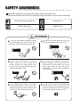
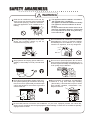
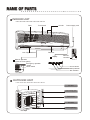
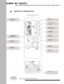
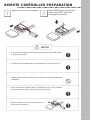
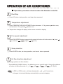
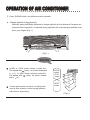
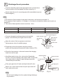
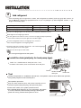
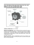
SPLIT AIR CONDITIONER
WALL MOUNTED TYPE
OWNER'S MANUAL
AGW52RH U.I./AGE52RH U.E.
Thank you for choosing an Air Conditioner.Please read this OWNER'S MANUAL carefully prior to using, keep it for further reference.
CONTENTS
P
Contents ................................................................... 1
2
Safety Awareness.................................................................2
Name or Parts ......................................................................4
Operation procedure
Remote Controller's Preparative Before Operation........................6
Operation Explanations of Air Conditioner..................................
7
Service and Maintenance of the Air Conditioner.....................12
12
14
Fault Confirmation and Analysis ...........................................14
16
Performance Parameters ....................................................16
17
Installation Explanations ......................................................17
SAFETY AWARENESS
Read and understand thoroughly this safety awareness before use.
The items indicated here are very important safety precautions, which must be followed.
Must connect grounding line
Absolutely no
Must unplug plug
Must be done
WARNING
Do not pull power cable. Hold plug to unplug
when removing power, or part of the line in
the power cable may break and cause fire.
Do not let cool air blow directly at you for long
time.Possible health problems may occur.
Do not connect at the middle of the power
cable or extend it. Do not use multi - hole
sockets. Possible fire electric shock may
occur for poor connection,bad insulation and
excessive allowable current.
Do not plug power cable when in operation.
(Spark may appear, and cause fire.) Pull the
power plug out from the outlet or cut off the
power supply when you don't use the air
conditioner for a long time. (Accumulated dirt
will cause fire.)
Do not damage power cable, or do joining
work.By putting stuffs on the power cable,
heating it or do joining works,a possible short
circuit may cause fire and electric shock.
Provide a power outlet to be used exclusively
for each unit, and a power supply disconnect
and circuit breaker and current fuse protector
should be provided in the exclusive line.
SAFETY AWARENESS
WARNING
Clean the air conditioner with a soft and dry
cloth. Do not use chemical solvent,insecticide,
Inflammable-spraying material or which damage the appearance of air conditioner for cleaning.
The appliance shall be installed in accordance
with national wiring regulations.
The appliance must not be installed in the laundry.
The appliance must be installed 2.3m above
the floor.
An all-pole disconnection device which has at
least 3mm separation distance in all pole shall
be in corporated in the fixed wiring according
to the national rule.
Do not put burning appliances at the place
where can be blown directly by the air,
insufficient burning may occur.
Do not install the air conditioner in where leak
flammable gas. If there is electrical leakage
accidentally from air conditioner, it is easy to
cause fire or explosion ,as is very dangerous.
Stop operation and unplug power cable immediately if abnormality is found ( burned smell
etc ).
Do not use for special purposes. Do not use to
store precision equipment,food,painting etc, which are required humidity and temperature, for
their quality may be affected.
Close doors and windows ( better using contains )while operating air conditioner for a long
time,if room air is quite turbid,you should open
a door and window for a moment to get some
outdoor fresh air.
Do not operate air conditioner at COOL/DRY
mode for a long time under high humidity
( above 80%), if door/window is open or under
high humidity condition, condensation may
drop from the unit.
Do not install, service or move the Air Conditioner on your own. Improper process can cause fire,
electric shock, the falling unit can injure people or water leakage. Contact our air conditioner specially
engaged service center.
NAME OF PARTS
INDOOR UNIT
Filter
Front panel
Air inlet
Power supply cord
SWING
MANUAL
Left / Right deflector
Deflector
OPERATION
MODE
OFF
ON
TIME
CANCEL
Display
Remote
controller
I/O
SET
FAN SPEED SLEEP
Manual operation
(open the Front panel)
Emergency operation
switch
Check switch
Time indicator
Sleep indicator
Run indicator
OUTDOOR UNIT
Air inlet
Connecting pipe
Drain hose
Air outlet
Drain opening
NAME OF PARTS
REMOTE CONTROLLER
Signal ejecting window
SWING
BUTTON
OPERATION
DISPLAY
MANUAL SWING
BUTTON
OPERATION
MODE BUTTON
TIME OFF
BUTTON
TIME ON
BUTTON
TEMPERATURE
ADJUSTMNT
BUTTON
TIME CANCEL
BUTTON
RUN/STOP
BUTTON
TIME SET
BUTTON
FAN SPEED
BUTTON
SLEEP
BUTTON
RESET PIECE
NOTICE
cool only type hasn't HEAT mode
5
REMOTE CONTROLLER PREPARATION
Open back cover, put in batteries.
Short RESET piece with forceps.
(Short two RESET piece after
changing the batteries.)
NOTICE
•
If the remote controller can't be operated normally, short two RESET piece,
it will operate normally.
•
The signal can be reached within six metres directly in front of indoor unit.
•
Handle remote controller carefully. Do not drop, throw and get wetted. Avoid
malfunction.
•
When the button is pressed, indoor unit will beep once or twice, indicating
the receiving of the signal. If no beep is heard, press again.
•
Remove batteries if Remote controller has not
been used for a long time.
6
OPERATION OF AIR CONDITIONER
Operation procedure-Control under the Remote controller
1
Run/Stop
Press I/O button, start operation, and stop when repressed.
2
1
Temperature adjustment
Press TEMPERATURE ADJUSTMENT button,decreases 1 C by press
and increase 1 C by press
button once.
button once,
Temperature change will display in the remote controller's display.
3
Fan speed adjustment
Press FAN SPEED button,change the fan speed of indoor unit in the order of
( medium )
( high )
( auto ).
4
( low )
Sleep selection
Press SLEEP button, set sleep operation, and cancel when repressed.
5
1
Air flow direction adjustment
Change up/down air flow direction
1 Press MANUAL SWING button, the deflector move a specific angle. Change the deflector
of indoor unit follow the order of
NOTICE
(1)
(2)
In DRY or COOL mode , air blows downward in
(3)
(4),
(4)
(5) (Fig.2)
(5) for one hour,
it changes to horizontal blowing automatically to prevent dropping.
OPERATION OF AIR CONDITIONER
2 Press SWING button, the deflector start to opreate..
Change right/left air flow direction
Manually swing Left/Right deflector,to change right/left air flow direction.Complete adjustment before operation, if adjusted during operation,the auto swinging deflector may
pinch your fingers.(Fig. 1)
( Fig.1 )
ADVICE
In DRY or COOL mode, advise to make the
Fan speed with (auto), air blows downward
in (1). In HEAT mode, advise to make the
Fan speed with
(auto), air blows downward in (4).
Control with remote controller to adjust up/down air flow direction, avoid turning deflector
with hand to avoid injury.
COOL
mode
DRY
mode
(1)
(2)
(3)
HEAT
mode
(4)
(5)
( Fig.2 )
OPERATION OF AIR CONDITIONER
61
Operation mode adjustment
Cool only type has not HEAT mode .
1 AUTO mode
When started, operation mode will turn into COOL or DRY or HEAT mode as per room
temperature, if operation stops for two hours, it restarts in the same mode set as before
operation was stopped. Once operation mode is set,it will not be influenced even if room
temperature has changed.Press MAUNAL SWING button or SWING button to change
up/down air flow direction.
Per Room
Temperature (RT)
above 26 C
25-26 C
23-25 C
below 23 C
Cooling only type
Mode
Cool
Per Setting Temperature
24 C
Dry
RT-2
RT-2
Heat pump type
Mode
Cool
Dry
Heat
Per Setting Temperature
24 C
RT-2
RT-2
26 C
2 COOL mode
Press MAUNAL SWING button or SWING button to change up/down air flow direction.
Press FAN SPEED button to change the fan speed of indoor unit. Press TEMPERATURE
ADJUSTMENT button to change the setting temperature.
3 DRY mode
Press MAUNAL SWING button or SWING button to change up/down air flow direction.
Press FAN SPEED button to changes the fan speed of indoor unit.
4 FAN mode
Press MAUNAL SWING button or SWING button to change up/down air flow direction.
Press FAN SPEED button to change the fan speed of indoor unit.
5 HEAT mode(heat pump type)
Press MAUNAL SWING button or SWING button to change up/down air flow direction.
Press FAN SPEED button to change the fan speed of indoor unit. Press TEMPERATURE
ADJUSTMENT button to change the setting temperature.
ADVICE
1 HEAT mode: Healthy warmness lies in the difference with outside temperature! The
setting temperature for heating shall not be too different from outside temperature.
Though it varies with area, set temperature to between 20 C- 24 C , Heating effect
becomes inferior when ambient temperature is below 5 C .
OPERATION OF AIR CONDITIONER
71
Timer operation
Timer operation ON
1 Press button
ON
when air conditioner stops ,
of
on the
¡flicker
±
¡ ±Remote
Controller display.
OFF
Press button
when air conditioner operates ,
Remote Controller display.
2 Press button
ON
OFF
of
¡ ± flicker on
¡ ±the
ON
or
to enter time setting . press button
or
the timer will increase 1 hour, the time will display on remote controller .
3 Press button
to fix setting time .
Remote Controller display.
or
SET
OFF
one time,
will be stop flicker on the
Timer operation OFF
If you want timer operation goes off, press button CANCEL Untill set time
¡ ° ¡ and
±¡ °
or
will disappear on the remote controller display.
¡±
NOTICE
1.If power sets off, time must be set again, otherwise, timer operation is not right.
2.If the air conditioner has been in time on or time off, but you want change the time, you must
cancel the primary condition then can set new time condition, otherwise, error will occur.
3.After having chosen the time mode, if you press the
SET
once incautiously, the setting time
will count time anew automatically as primary setting time, and the display time will not change.
So if you want air conditioner operate as primary setting time, you must set time anew .
Operation procedure-Control under the Emergency operation switch
In case the batteries in the remote controller are
wore out, or remote controller is at fault, use emergency operation switch.
(Cool only type)
Every time the switch is pressed, it changes in
sequence of COOL
STOP.
(Heat pump type)
Every time the switch is pressed, it changes in
sequence of COOL
HEAT
STOP.
Emergency run operation procedure as the following:
Setting temperature
Fan speed
Deflector
24 C
High
Swing
SERVICE AND MAINTENANCE
Air Conditioner no use for a long time.
1
Start fan only for 3-4 hours to completely dry the inside of the indoor unit.
Set COOL mode or HEAT mode,
and select the highest setting temperature, then fan turns.
Want to use the Air Conditioner
1
ION
ERAT
Clean filters and replace them to original position.Clean indoor unit with soft
clothe.
Do not use gasoline, benzene, thinner,
grinding powder, detergent,insecticide
etc. to clean units as they can hurt the
units.
OP
FAN
2
Turn off air conditioner, unplug the
power plug,otherwise, the accumulated dirt may cause fire.
2
3
Take the batteries out of the remote
controller.
3
Inlets and outlets of indoor and outdoor units shall not be covered/blocked.
Ground wire shall not be loose.
Put in batteries, and plug the power
plug.
SERVICE AND MAINTENANCE
Deodorization filter, Air cleaner, Filters must be cleaned termly.
Open front panel only after air conditioner stops completely.
Filters should be cleaned once every two weeks.
Clean deodorization filters and air cleaner.
1 Take out filters.
1 Take out filters first, then take out
2 Clean filters with a vacuum cleaner
2 Clean deodorization filter, air clean-
3 Clean filters with clean water, then
3 Clean filters with clean water, then
or by typing them gently. ( If they are
very dirty, wash them in warm water
below 45 C dissolved with neutral
scouring agent.)
dry them in cool air.
4 Insert them at original position, then
push down and close front panel.
deodorization filter and air cleaner.
er with warm water below 45 C
dissolved with neutral scouring agent.
dry them in cool air.
them at original position, then
4 Insert
push down and close front panel.
FAULT CONFIRMATION AND ANALYSIS
If problems can not be corrected after doing below items, please
stop the air conditioner, contact our air conditioner specially engaged service centre nearest to you to get help.
Is there a fault ?
Air conditioner does
not operate at all.
Remote controller is not
available and does not
display.
It is not running
after I/O button
is pressed.
Cooling and heating
efficiency is not good.
Fault analysis
Does power fail ?
Is plug out ?
Does power fuse or switch off ?
Is voltage higher than 253 V or lower than
207V?
Is time set suitable?
If disturbed abnormally or operation modes
changed too frequently, sometimes the remote controller would lose function. Please
plug out and plug in again, it may be ok.
If remote controller displays unclear or displays all symbols, please change batteries.
This is a way to protect compressor as per
microprocessor instructions. Please wait 3
minutes.
Does temperature set suitably ?
Are filters dirty?
Are inlets and outlets of outdoor unit blocked?
Does sleep function start during daytime?
Does indoor fan speed set low ?
Are doors and windows closed ?
Air will not immediately
blow out at the start
of HEAT mode.
It is processing information, air will only blow
out when sufficiently warm. Please wait.
FAULT CONFIRMATION AND ANALYSIS
Is there a fault ?
Indoor unit fan stops
for about 10
minutes during
heating.
Fault analysis
It is defrosting of the outdoor unit coil.It should
complete this process in about 10 minutes at
most.( It freezes when outdoor temperature is
low and humidity is high. )
Issues cracking sounds
The friction sounds caused by expansion and
contraction of front panel resulting from temperature changes.
You can hear the
sound of running
water
It is the sound of expanding refrigerant inside
the air conditioner.
Sound of accumulated water dropping on the
heat-exchanger.
Melting sounds of frost on heat-exchanger.
Indoor unit issue
pooosh
sound and click
sound.
Click sound of fan or compressor when switching ON/OFF.
pooosh sound of refrigerant inside the air
conditioner.
There is odd odor
in the air that air
conditioner blow out.
Outdoor unit leaks
water.
Air conditioner recycles should have absorbed
odors from wall, carpet , furniture and cloth
closet out into the air.
During cooling, connecting pipe or pipe connector is cooled to form condensates.
During heating or defrosting , melting water
and water vapor will run out.
During heating, water on heat-exchanger will
drop.
PERFORMANCE PARAMETERS
Model
Function
Power
Rated cooling/heating capacity (BTU)
Standard input power (W)
Standard input current(A)
Air flow volume(m 3 /h)
Dehumidifying capacity (L/h)
Protection class
Water-proof
Climate type
Refrigerant (R407C) charge amount(g)
18000BTU
indoor
outdoor
heat pump type
230V ~, 50Hz
18100(cool)/19700(heat)
2010(cool)/2340(heat)
9.8(cool)/10.6(heat)
750
2.5
I
IP20(Indoor) IP24(Outdoor)
T1
2000
Net weight (Kg)
43
14.5
56
46
Dimension(mm)HXWXD
315x1020x178
690x860x370
Noise dB(A)
1 The indicated noise value is from laboratories test before leaving factory.
2 The rated cooling capacity and rated heating capacity value is tested under below conditions
cooling operation
indoor
27 C(DB)
19 C(WB)
outdoor
35 C(DB)
24 C(WB)
NOTICE
heating operation
indoor
outdoor
20 C(DB)
15 C (WB)
7 C(DB)
6 C(WB)
3 All above should be changed without notice.There are latest and accurate specifications on the name plate of
your air conditioner.
4 Working temperature range:
Maximum cooling Minimum cooling Maximum heating Minimum heating
Indoor side DB/WB( C)
32/23
21/15
27/--
20/--
Outdoor side DB/WB( C)
43/26
21/15
24/18
-5/-6
5 If air conditioner working voltage exceeds 230V 10%.it operates abnormally.
6 Wiring diagram of air conditioner(indoor unit/outdoor unit)are attached to the unit.
7 If the power cable or connecting cable is damaged ,it must be replaced by the manufacturer or its service agent
or similar qualified person in order to avoid a hazard.
INSTALLATION SKETCH
Installation sketch
105m
m
above
155mm
above 24mm
above
Confirm installation place with
the marker of indoor unit installation board.
1
2 3 4
Notice:do not put the
drain hose high.
G
above 7mm
7
H
F
C
B
D
Configuring pipe can be
installed to back, right,
underside, or left-back
side.
front
back
right
left
back
underside left-back
above 100mm
6
5
abov
e 10
Cover connecting pipe with
heat-isolating material.
0mm
a
mm
100
e
v
bo
9
a
e 50
bov
0mm
E
A
abo
ve 3
50m
m
the thickness of heatisolating material is
8mm.
Put the wood block with the thickness above 20mm between the
wall and conncting pipe, or cover
connecting pipe with bonding tape
of 7 or 8 layers, when install connecting pipe on the wall that is
metallic net or thin armor plate.
INSTALLATION ACCESSORIES
Before installation, inspect the following accessories:
Indoor unit accessories
Quantity
Installation accessories
Quantity
1
A
Connecting pipe screws
4
5
B
Bonding tape
1
Expansion rubber plug
5
C
Clamp
3
4
Expansion bolt
2
D
Cement nail
5
5
Battery
2
E
Drain hose
2
6
Remote controller
1
F
Opening cap
1
7
Felt
1
G
Wall-hole cover
1
8
Adiabatic underlay
1
H
Indoor wall-hole cover
1
9
connecting cable+signal wire
1+1
I
putty
1
10
Deodorization filter+air
cleaner
1+1
J
Airproof oil
1
1
Mounting plate
2
Tapping screw ST4
3
25
Installation Instructions
1
Location of indoor unit
Cooled or heated air should be blown
to every art of the room.
Maximum height between indoor/outdoor units is 5m.
Mount on firm wall to avoid any vibration.
Avoid direct sunshine.
Easy to drain condensate water.
Do not make any interference caused
by the fluorescent lamp to the remote
controller's signal.
Minimum distance between air conditioner and home appliance( TV/ Radio
etc. ) is 1m.
2
Location of outdoor unit
Airflow can not be blocked.
Good ventilation, low dust,avoids rain
or direct sunshine.
Operation noise or air blowing out will
not affect neighbors' comfort.
Firmly mounted on rack,which will reduce noise and vibration.
Avoid places close to inflammable
gas leakage.
Unit must be mounted firmly when
installed high up.
Not to be affected by strong wind.
INSTALLATION
INDOOR UNIT
1
Secure the mounting plate
The mounting plate should be attached to the structural part of wall (post etc.).
fasten string at the central hole
at least 60mm
245mm or more
from sidewall
175mm or more
from sidewall
mounting plate
The holes at solid arrow position must be secured to avoid the shake of mounting plate.
When the expansion bolts are used, two holes ( 11 20 or 11 26 ) that the distance
between them is 450mm should be adopted.
NOTICE
2
° ²× °Ë µÃ ÷
plumb
Drill on the wall
right rear piping
Left rear piping
28mm
12mm
Center
Center
65mm
65mm
12mm
12mm
Confirm the position of holes, and drill holes of
3
65mm on the wall.
Wiring
Electrical box cover
Screw
1 Open the front panel;
2 Remove the screw from electrical box cover, pull the
electrical box cover away from the unit and set aside.
3 Remove the screw from fastener, pull the fastener
away from the unit and set aside.
4 Connect the cable.
5 Replace the fastener and electrical box cover.
Indoor unit
terminal
Diagram
Fastener
Screw
Pull the connecting cable's
wire in completely
Connecting cable
Indoor unit terminal
Connecting cable
INSTALLATION
41
Installation drain hose
liquid pipe
1 NOTE:
The drain hose must be arranged beneath the copper pipe.
The drain hose must not be hunched or bended.
Do not wrap the drain hose by pulling it.
When the drain hose must be through the house, it should be
wrapped by the special heat insulated materials.
The copper pipe and the drain hose must be wrapped by felt
strip. Heat insulated pad should be used in the place that the
pipe contact the wall.
gas pipe
drain hose
adiabatic
underlay
felt
2 ROUTE OF PIPE
If pipe came out of the right side of the indoor unit, cut part
1
1 on the unit;
If pipe came out of the lower-right side of the indoor unit, cut part "2" on the unit;
If pipe came out of the left side of the indoor unit, cut part 3
on the unit.
3
2
3 REFIT OF DRAIN HOSE
If pipe comes out of the left side of the indoor unit,the drain hose
must be refit, otherwise water leakage may occur.
Refit methods: Interchange the position of drain hose and drain
rubber bib, the right diagram is un-refit position.
Clearance is not allowed after refit, it would lead to water leak.
51
Drain
Drain cap
Installation indoor unit
After setting the clamping cover of piping in the
hooks in the direction shown by the arrows and
in the order shown by and to fix it temporarily,
then tighten the piping cover fixing screw to fix
it securely.
Insert the piping through a hole in the wall, and
hook the Indoor unit onto the upper position of
installation plate (engage the two hooks of the
rear top of the indoor unit with the upper edge
of the installation plate)
61
Tapping
Piping
Drain hose
Piping cover
fixing cover
Clamping cover of piping
Arrangement of drain hose
To eject the condensate water easily, the drain hose should be declined downward.
The arrangement in diagram2-5 is wrong.
decline
downward
decline
downward
standing
water
dip hose in water
air
water
leak
(Fig. 1)
water
leak
(Fig. 2)
(Fig. 3)
50mm or less
from floor
(Fig. 5)
(Fig. 4)
drain hose
If the drain hose connected with the indoor unit is short, it may
be extended by the hose in the accessory box.
When the drain hose must be through the house, it should be
wrapped by the special heat insulated materials.
hose(ID 15cm)
PVC hard
INSTALLATION
71
Seal of wall hole and fasten of pipe
Use putty to seal the
wall hole.
Use clamp ( pipe fastener ) to secure
the pipe at specified
position.
get rid of unwanted part
clamp
airproof with putty
clip the connecting pipe with clamp
screw
indoor unit
OUTDOOR UNIT
1
Wiring
Connect diagram
Outdoor unit terminal
N234
Connecting
cable
Connecting
joint
Indoor unit terminal
Connecting
Red
cable
White
Blue
Yellow/Green
Blue Brown
Yellow
N234
Outdoor unit terminal
Heat pump type
WARNING
Model
The connecting cables must be clipped together.
Special cable must be used to connect indoor unit and outdoor
unit. It should be ensured that the terminals are not influenced by
external force. Poor connect may cause fire.
The electric box cover must be mounted and secured in position,
otherwise fire or electrical shock may occur because of dust or
moisture.
18000BTU can be connected only to a supply with system impendance
no more than 0.160 . In case necessary, please consult your supply
authority for system impendance information.
Power Supply Wiring length(m) Power line max.length(m)
2
Control ine length (m)
Cross section area(mm )
2.5
2.5
0.75
18000BTU
2.1
10
10
21
Delay fuse(A)
25
Flaring the pipe end
Oblique
Cut the pipe using a pipe cutter.
Remove burrs at the tip of the pipe cut.
Insert a flare nut into the pipe and modify flare.
Outer diameter(mm)
Burr
Reamer
Raughness
Burr
31
Discharge the air procedure
Connect assembly pipe to the appropriate valve on the indoor
unit and outdoor unit and tighten the flare nut(as fig.1).
Screw down the nut of connecting pipr with wrench(the torque as
follow diagram )
(Fig.1)
NOTICE
1.The number of bent position of the pipe in the indoor unit should not exceed 10.
2.The number of bent position of the pipe in the indoor unit and the outdoor unit should not
exceed 15.
3. The radius of bent position should more than 10cm.
PIPE
DIAMETER OF PIPE
MIN.THICKNESS
TORQUE(N m)
Liquid pipe
6.35mm ( 1/4
)
1.0mm
13.7---17.6
Gas pipe
12.7mm ( 1/2
)
1.0mm
49.0---56.4
Connect charging hose(low pressure) of manifold
gauge to the service port of gas shut-off valve.
Open the valve of the low pressure and close
high pressure valve of manifold gauge.
liquid connecting pipe
liquid shut-off valve
Allen wrench
gas shut-off
gas connevalve
cting pipe
Valve nuts
Service port
Purge the air from the system using the vacuum
pump until its pressure(low pressure side) is below 12Pa.
Service port cap
(Fig.2)
Close the low pressure valve and remove the charging
hose from service port .
Manifold gauge
Use Allen wretch to turn the valve cork of liquid side
for 90 in counter-clockwise, and close it after 10 seconds.
Low pressure
Use soapy water to check for gas leakage especially
valve
fromservice port and flare.
Pressure meter
High pressure
valve
Charging line
Fully open gas shut-off valve and liquid shut-off valve.
Mount the valve nuts and service port cap to shut-off
valve and service port .
Vacuum
pump
Service port
NOTICE
Do not let air leakage into the system during discharge
air procedure.
(Fig.3)
INSTALLATION
41
Add refrigerant
If the connecting pipe is longer than 7 meters, add refrigerant as needed. (Cool only type) add amount A=
(Lm-7m) 15g/m ; (Heat pump type)add amount A= (Lm-7m) 50g/m. (A: add refrigerant amount , L: the
length of connecting pipe)
the length of connecting pipe (m)
7
8
9
10
15
(Cool only type)add amount (g)
0
15
30
45
120
(Heat pump type)add amount (g)
0
50
100
150
450
The limit of tubing length is 15 and the limit of elevation difference is 7m.
Discharge air as foregoing method.
Turn the gas shut-off valve to close, connect charging hose(low pressure)
to the service valve, then open gas shut-off valve again.
Connect refrigerant bottle to charging hose, convert it,
then fill liquid refrigerant as foregoing table.
Close the gas shut-off valve, disconnect the manifold gauge,
and open gas shut-off valve again.
R407C
Tighten nuts and cap of each valve.
NOTICE
Do not let gas refrigerant into the system.
Service port
Install the drain joint(only for heat pump type)
Install the double-channel drain joint in the hole
of outdoor unit's bottom, then connect drain hose and joint.
Bottom
Test
double-channel
drain joint
Drain hose
Having accomplished air installation and leak test , test operation must be done. Before test operation,
wiring safety inspect must be carefully done.
Test operation procedure:
Only can check switch be done, and remote controller can not.
1.Connects system with power plug, and open front panel.
2.Press check switch, then system operates as test.
3.If the indicate lamps light first, go out in succession, the system
is normal, otherwise, there has lamp flashing indicating that
system has wrong. Please check system for once.
Via Varese,90
21013 Gallarate(VA)
Italy
Phone:+39 0331 755 111
Fax:+39 0331 766 240
www.argoclima.com