1
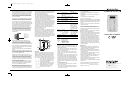
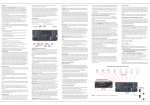
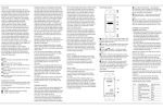
AB2 Owner’s Manual
1/25/08
4:25 PM
Page 1
Introduction
Thank you for choosing this Harman Kardon® product.
With your purchase of a new AB 2 Amplified In-Wall Module
you will be able to extend the flexibility of your home entertainment system so that it delivers sound to another room
in your home. Custom-designed for use exclusively with
Harman Kardon A-BUS® -equipped products and ABH series
hubs, the AB 2 enables you to send a separate source to the
remote room and power most speakers – without the need for
an additional amplifier – through one single Category 5/5e cable.
The keypad and built-in IR sensor, compatible with the included
remote and Harman Kardon AVR and second-zone remotes,
offer control over source selection and operation, local volume
and system power.
To fully enjoy the benefits of remote keypad control, please take
a few minutes to read this owner’s manual. It contains important
information that will guide you through the correct and safe
installation of your Amplified In-Wall Module. If you do not have
experience installing in-wall electrical and telecommunications
components, consult a qualified low-voltage contractor or
custom installer.
If you have any questions about this product, its installation or
its operation, please contact your retailer or custom installer.
They are your best source of product information.
Features
■ Simple connection to any A-BUS-equipped Harman Kardon
product or ABH series hub
■ 8-Key button control for source selection, transport control,
volume up/down and mute
■
■
■
■
Built-in IR sensor for control of compatible sources; remote
included
Decora®-style wall plate (not included) blends perfectly with
other in-wall electrical controls
Mounts in standard electrical junction boxes or plaster rings
Uses standard Category 5/5e cable
Important Safety and Installation Information
Low-voltage wiring systems must be properly installed to minimize the possibility of accidental contact with hazardous power
and lighting wiring. Never place audio or remote control wiring
near bare power wires or lightning rods, antennas, transformers,
steam or hot water pipes, or heating ducts. Never run low-voltage
wire in any conduit, box, channel, duct or other enclosure
containing power or lighting circuits of any type. In addition to
ensuring proper separation between any AC power wiring and
the Category 5/5e cable used for A-BUS, avoid running the
A-BUS cable in parallel to any AC wiring. Always maintain at
least the minimum separation between AC wiring and the A-BUS
cable or ANY low-voltage cable that is required by the NEC
(National Electrical Code) or any applicable local building codes
or regulations.
Make sure to follow all instructions when preparing wiring for
use with the AB 2 module. Failure to do so may result in a
potential safety hazard, including possible danger to persons
and/or equipment.
If you will be running the cable through a ventilation riser or
plenum, use plenum-rated cable to comply with NEC and local
electrical codes. Failure to do so may result in a potential fire
or safety hazard.
Always observe the appropriate safety codes for concealed
wiring. Be extremely careful not to cut through or drill into
concealed wiring or pipes. Make a small inspection opening
before cutting or drilling.
Dust or dirt can cause special problems on wiring contacts.
Be sure all contacts are clean, and that all parts are installed
correctly to protect them from dust and dirt.
Your Harman Kardon AB 2 Amplified In-Wall Module has been
custom-designed for use with Harman Kardon A-BUS-equipped
products; it is also compatible with many other A-BUS-compatible
systems. Do not connect it to any other device.
The AB 2 is only to be installed by qualified personnel and as
per the requirements of all applicable state and local building
codes, as well as NEC requirements. Check with your local
authorities as needed to ensure that all wiring inside walls is
installed in compliance with the proper standards. Failure to
do so may present a potential safety hazard.
If you have any doubt about your ability to work with electrical
and telecommunications wiring, you are advised to hire a
licensed electrician or custom installer to install this product.
What Is Included
• Two self-starting, universal-head machine screws for mounting
• Remote control
You are responsible for providing a Decora-style wall-plate,
available in a variety of colors at your local hardware retailer.
You must also provide the speakers and a sufficient length of
Category 5/5e (or better) UTP (unshielded twisted pair) cable
and an RJ-45 modular plug. The wiring scheme is the standard
TIA T568A configuration. The maximum length should not
exceed 100 feet to avoid degrading the signal. Further information on the correct wiring configuration is provided in Step Two.
Front-Panel Controls
Wall-Plate Screw Hole
Mounting Screw Slot
AVR Tuner/DMP Control
CD Source Control
Power Off/Mute
Skip Up/Down
DVD Source Control
Installation Planning
The AB 2 may be installed in any location appropriate for
standard in-wall electrical components. You are responsible for
selecting and properly installing an appropriate electrical junction
box or plaster ring. Check the fit of the box or ring with the
AB 2 before installation.
Since the AB 2 uses a built-in infrared sensor to receive commands,
avoid installing it near potential sources of interference, including
plasma video displays, dimmer-controlled lighting, bright sunlight,
and reflective surfaces such as mirrors or blank walls. Temporarily
place the AB 2 in the proposed location to test the integrity of
IR signals.
The AB 2 should be installed in a convenient place where it
may be operated manually, or by using a remote control from
any place in the room. The AB 2 may be mounted close to
other wall switches, but it should NEVER be installed in the same
gang box as any product (e.g., light switch or dimmer) where
AC line voltage is present.
Consider the distance from the AB 2 module to the speakers,
particularly when they are in-wall or in-ceiling mounted. Be certain
that there are no solid walls or load-bearing structures that
would prevent the speaker wires from reaching their location.
The cable used to connect the AB 2 to the A-BUS-equipped
receiver or hub should be Category 5/5e (or better). Be certain
that any local building or electrical codes mandating the use
of plenum or riser wiring are taken into account. The speaker
wiring should be in-wall rated as required, and may not exceed
14 AWG. To simplify wiring, you may use two-pair CL-3 rated
in-wall wiring and run a single cable from the AB 2 to both locations. One pair will be used to connect the first speaker and the
other will continue to the second speaker.
NOTE: To ensure proper performance, the cable length
between an A-BUS source component and the AB 2
should not exceed 100 feet.
Speaker Selection
The AB 2 is compatible with in-wall or in-ceiling speakers that
have an efficiency rating of 88dB or greater, and a minimum
speaker impedance of six ohms.
Volume Up/Down
MP3 Source Control
IR Sensor
Status LED
Mounting Screw Slot
Wall-Plate Screw Hole
Wall-Plate Screw Holes – Use these screw holes to attach
your Decora-style wall plate to the AB 2.
Mounting Screw Slots – Use the supplied machine screws
to attach the AB 2 to an electrical junction box or plaster ring
through these slots.
Volume ⁄/ ¤ Buttons – Press these buttons to raise or
lower the volume of the speakers connected to the AB 2.
Temporarily mute the system by tapping the Power Off button.
To unmute the system and return to the previous volume level,
tap the Power Off button again.
IR Sensor – This sensor receives signals from the included
remote control, the main or second-zone remote supplied with
some Harman Kardon multizone receivers, or a source remote,
and uses them internally or passes them on to other components.
When a command is received, the Status LED blinks and the
AB 2 sounds a tone through the speakers connected to it in
acknowledgement of the command. The operating range of
the infrared system is up to 60 feet in ideal lighting conditions,
and up to 15 feet in bright sunlight.
Status LED – The LED behind the red window indicates the
system’s status.
Press and hold this button to select The Bridge/DMP as the
multiroom source. If a compatible iPod (not included) is docked in
The Bridge, it will begin playing. The Bridge is a Harman Kardon
accessory that is sold separately. It may be connected to a
The Bridge-Ready Harman Kardon product.
CD Source Control – When the AB 2 is used with a Harman
Kardon ABH 4000 or other compatible multizone A-BUS hub,
and when a CD player is connected to Source 2 of the hub,
tap this button to select the CD player as the source and begin
play (if the player was not already playing). Tap the button again
to pause play. If audio is not heard within a few moments of
the first tap, tap the button again, as the CD player may have
already been playing and would have interpreted the command
as a Pause.
If this button was previously tapped to start play, press and
hold the button to skip to the next disc (assuming the player is
a multidisc unit).
DVD Source Control – When the AB 2 is used with a Harman
Kardon ABH 4000 or other compatible multizone A-BUS hub,
and when a DVD player is connected to Source 3 of the hub, tap
this button to select the DVD player as the source and begin play.
If this button was previously tapped to select the DVD player as
the source, press and hold the button to begin play.
MP3 Source Control – When the AB 2 is used with a Harman
Kardon ABH 4000 or other compatible multizone A-BUS hub,
and when an MP3 player is connected to Source 4 of the hub,
tap or press and hold this button to select the MP3 player as
the source.
Power Off/Mute – Tap this button to mute the AB 2. Tap it
again to resume hearing audio. Muting the AB 2 does not affect
the source, which will continue playing.
If the AVR’s tuner or The Bridge is the current source, or if the
AB 2 is connected directly to the AVR, press and hold this
button to turn off the AVR’s multiroom system. If any other
source has been selected and the AB 2 has been connected
to a hub, press and hold this button to power off the hub.
Skip Up/Down – Tap this button to skip up, and press and
hold it to skip down. The precise behavior depends on the
current source:
• AVR Tuner: Preset up or down; no effect on The Bridge
• CD: Track skip up or down
• DVD: Next or previous chapter
• MP3: No effect
Speaker-Terminal Block – The wire used to connect the
AB 2 to your speakers is connected to this terminal block.
Insert the wire in accordance with the color coding shown and
then tighten the screw. The maximum wire size is 14 AWG.
Installation and Connection
IMPORTANT SAFETY NOTES:
• Before beginning the installation process, make certain
that all electronic products in the system are turned off
and disconnected from their A/V power connection.
This avoids the possibility of accidental activation,
which could possibly damage the equipment or cause
personal injury. Do not turn on the equipment until
instructed to do so.
• Be certain to observe all appropriate safety measures
when installing any wiring, including, but not limited to,
the use of eye protection when required, and attention
to the required distances between low-voltage wiring
and high-voltage AC mains wiring.
Step One: Run a Category 5/5e cable from the receiver
or hub location to the module.
Run a splice-free Category 5/5e cable from the location where
the AB 2 module will be installed to the location where the
A-BUS-equipped product or hub is placed. Leave sufficient
wire at each end for ease of installation. Any extra wire may
be trimmed back during the installation. You will need to have
access to the rear of the AB 2 after the module is connected,
but before the module is secured into the wall box.
Step Two: Prepare and install an RJ-45 plug at the
receiver end of the system.
The connection and cable termination at the receiver or hub end
of the installation is a standard RJ-45 connector using the TIA
T568A configuration.
Connect an RJ-45 plug to the end of the wire as follows.
Looking at the connector with its clip on top and the wires
coming out of the connector toward you, numbered from right
to left, the typical pin colors are as follows:
Striped Wire Pairs
Signal
1
Green and White
Left Channel Ground
2
Green
Left Channel
3
Orange and White
Right Channel Ground
4
Blue
IR
5
Blue and White
Status
6
Orange
Right Channel
Output-Level Trims
7
Brown and White
Ground
Input-Cable
Connection Block
8
Brown
+24V DC
Speaker-Terminal Block
• When the LED is at full brightness, the system is operational.
AVR Tuner/DMP Control – Tap this button to turn on an
A-BUS-equipped Harman Kardon A/ V receiver’s (AVR’s)
multiroom system and select the tuner as the multiroom
(remote-zone) source. Each additional tap changes the tuner band.
Output-Level Trims – Use these trim pots prior to final installation to match the output level of the AB 2 to your speakers.
Pin #
Rear-Panel Connections
• When the LED is not lit, the AB 2 is not connected to a
powered A-BUS-equipped component or hub.
• The LED will blink when it is receiving an infrared command
code from a compatible remote control.
Input-Cable Connection Block – Using standard IDC punchdown tools, connect the Category 5/5e cable linking the AB 2
to the receiver or hub to this connection block in accordance
with the color code printed on the circuit board.
Note that one wire in each pair is always a solid color, and the
other is either white or striped. Make sure that the twisted pairs
of wires consist of those attached to pins 1 and 2, pins 3 and
6, pins 4 and 5, and pins 7 and 8.
4:25 PM
Page 2
When making the connections at each end of the cable, strip
the outer insulation jacket about 1-1/2" to 2" from the end. The
cable is constructed of four twisted pairs of wires, as indicated
above. Flatten the wire ends to prepare them for insertion into
the connector. Fully insert the wire into the connector, being
certain to check the color codes of the pin assignments one
last time. Carefully crimp the connector, making sure that each
wire is securely fastened.
Step Three: Connect the Category 5/5e cable to the AB 2.
Once the wire is run to the remote location where the AB 2
will be installed, connect the Category 5/5e cable to the AB 2.
Prior to making the connections, strip the outer jacket of the
Cat. 5/5e cable 1-1/2" to 2" from the end, taking care not to nick
the inner conductors. Next, separate the four twisted pairs within
the cable and then untwist the ends of each pair about 1/2."
All terminations are made at the Input-Cable Connection
Block. Connect the wires using standard 110 Insulation
Displacement Connector (IDC) tools and procedures. DO NOT
use screwdrivers to insert the wire into the IDC connection
points. Make certain that there are no shorts between any of
the individual wires, as this may cause damage to the AB 2.
From left to right, the connections are made as indicated in
the figure below.
Brown
Brown and White
Blue
Blue and White
Green
Green and White
Orange
Orange and White
the trim control down in the opposite direction until the clipping
stops. This is the correct level for your specific A-BUS-equipped
product and the AB 2. Before proceeding further, lower the
volume back to normal listening level.
Step Five: Connecting the AB 2 to the A-BUS-equipped
product.
After making certain that the connections to the speaker cable
and Cat. 5/5e cable have been made properly, plug the RJ-45
jack at the receiver end of the cable into the A-BUS jack on the
back of the A-BUS-equipped product.
Next, turn on the receiver or other source and turn on the
Multiroom system. As a confirmation that the system connections
have been made, the Status LED will light. When the AB 2
is turned on by pressing a source selector or using a remote
control to issue an IR command, the red LED on the Power Off
key will light, and a green LED will indicate the current source.
Step Six: Adjust the output levels.
This step sets the level adjustments for the AB 2. Once this
process is complete, all further volume settings are made with
the Volume Up/Down Buttons on the AB 2, the included
remote, or any compatible third-party remote.
With the Multiroom system activated and a source playing, press
the Volume Up Button for 20 seconds so that the AB 2’s
volume is set at its maximum. Next, adjust each of the OutputLevel Trims until the output begins to clip. At this point, back
Tap/ABR Remote
Press and Hold
(AB 2 only)
AVR
First press turns on
Selects The Bridge as
system and plays tuner;
the source and begins
additional presses change play
tuner band
Step Seven (Optional): Switch keypads.
You may switch keypads to better reflect the source devices
connected to the ABH 4000 or other multizone hub. The Power
Off/Mute, Skip Up/Down and Volume Up/Down keys remain the
same, but the source names change from AVR to TN (tuner),
CD to SAT, DVD to VID, and MP3 to The Bridge icon.
CD
Turns on system and issues Disc Skip
Play/Pause command
DVD
Play
To switch keypad sets, remove the AB 2’s white front panel by
gently pressing the four clips that secure it to the back of the metal
chassis. Be gentle so as not to inadvertently break off the clips.
Turns on system and
begins play
MP3
Turns on system and
begins play
Play
The entire keypad set may be removed and replaced, with the
small holes on the sides of the keypad frame fitting over the
corresponding pins on the back of the AB 2 front panel.
Power Off Mute
When replacing the front panel, orient it so that the red lens
fits over the red LED on the chassis.
Step Eight: Install the AB 2.
Place the AB 2 in the junction box or plaster ring, making sure
that any loose wire is carefully secured inside the wall or box,
and that there are no shorts between any of the connections.
Using the supplied mounting screws, attach the AB 2 to the
junction box or plaster ring through the Screw Slots. Attach a
Decora-style wall plate (not included) through the AB 2’s Screw
Holes. Although any color Decora wall plate may be used with
the AB 2, the AB 2 itself should not be painted.
Step Four: Connect the speaker cable to the AB 2.
Connect speaker wires to the AB 2 module using the colorcoded chart on the Speaker Terminal Block as a guide.
Observe the positive (+) and negative (–) polarity indications,
and avoid having the wire strands from one cable touch another.
Loosen the retaining screws on the Speaker Terminal Block
and insert the wire into the appropriate slots. Tighten the retaining screws to secure the wire.
Selector
Front
Panel
SpeakerTerminal
Block
OutputLevel Trims
Cover
Plate and
2 Screws
(not included)
Input-Cable
Connection
Block
1/8" x 3/4"
Machine
Screws (2)
(included)
J-Box
Wallboard
Operation
When the AB 2 is properly connected to the system and the
system is in standby mode (power is present but the A-BUSequipped product is powered off), the Status LED will light to
indicate that the system is ready to be turned on. When the
AB 2 is turned on, the red LED under the Power Off key will
light, and a green LED will light under the current source’s key.
Tap a source selector or use the ABR remote
to turn on the AB 2 and begin play. Some
source selectors offer additional commands,
as indicated in the table below.
NOTE: Some receiver models may require
you to manually turn on their multiroom
system before the AB 2 can be used.
Consult the owner’s manual for the
receiver for more information.
Powers system off
(if AVR is current
source, turns off AVR’s
multiroom system; if a
device connected to
the ABH hub is current
source, turns off hub)
Skip Up/ If source is:
Down
• AVR – Preset Up
(AB 2 only) • CD – Track Skip Up
• DVD – Next Chapter
• MP3 – No effect
If source is:
• AVR – Preset Down
• CD –Track Skip Down
• DVD–Previous Chapter
• MP3 – No effect
Volume Up Volume Up
Increases volume
Volume
Down
Volume Down
Decreases volume
System Off
(ABR
Remote
only)
If Source 1 is playing,
Not applicable
turns off an A-BUSequipped product; if
another source is playing,
AVR remains on and
ABH 4000 is turned off
The keypad itself offers local volume control and muting, and
limited source control. For more sophisticated control over the
AVR and source devices, point a remote at the IR sensor and
enter the desired command.
To turn off the AVR’s multiroom system, select the AVR as the
source and press and hold the Power Off key. The AVR’s main
listening area will not be affected.
If the AB 2 is connected to an ABH hub, turn off the hub by
selecting any source other than the AVR. Then press and hold
the Power Off key.
NOTE: Play/pause functionality may vary by model for CD
and DVD players. System power-off functionality may vary
for remotes other than the one included with the AB 2.
The operation of your AB 2 with a Harman Kardon AVR’s
second-zone remote may vary from model to model. Not
all features will work with all models. Functions requiring
“press and hold” are not available when a remote control
is used.
Troubleshooting Guide
• The source is turned on, media is loaded, and the Multiroom
mode is properly activated.
• Any needed volume-level adjustments on the receiver are
properly made.
• The volume control on the AB 2 is turned up and the AB 2
is not muted.
• The output-level trims are properly adjusted.
• Speaker connections are correct.
If the receiver or other components do not respond to commands
from the AB 2 or a remote pointed at the AB 2, make certain that:
• The A-BUS-equipped product’s Multiroom system has been
turned on.
• The Cat. 5/5e cable is properly connected to both the AB 2
and the receiver or hub.
• There is a proper connection between the A-BUS-equipped
product and any additional IR-controlled components.
• The remote is properly programmed to operate the receiver
and other components.
Other notes on using the AB 2 and other A-BUS products with
Harman Kardon A-BUS-equipped products:
• When using the AB 2 with Harman Kardon A-BUS-equipped
products, you may connect only one AB 2 at a time unless
an optional, external powered A-BUS hub is used.
• If A-BUS hubs or other A-BUS accessories not specifically
designed for use with Harman Kardon products are used,
their operation may be slightly different than with the AB 2.
AB 2
1/25/08
Amplified In-Wall Module
AB2 Owner’s Manual
• When experiencing problems during installation, connect one
source and one AB 2 to the A-BUS hub to confirm the hub
is working correctly. Then add sources and modules to the
hub one at a time to discover the source of the problem.
IMPORTANT NOTE: Turn off and unplug all power before
changing connections.
Specifications
• Wire type required: Category 5/5e (or better) cable in
compliance with any applicable local building code or NEC
requirements for in-wall, riser or plenum use.
• Wiring protocol: TIA wiring specification for T568A at the
A-BUS-equipped product end. Connections at the AB 2 are
specified on the AB 2.
• Connection terminals: IDC type for Category 5/5e cable;
screw terminal type for speaker connections.
• Speaker wire: Maximum AWG 14, in compliance with any
applicable local building code or NEC requirements for
in-wall, riser or plenum use.
• Speaker impedance: Suitable for connection to speakers
with nominal 6 ohms to 8 ohms impedance.
• Speaker sensitivity: Optimized for speakers with sensitivity
above 88dB.
• Infrared compatibility: 38kHz and 56kHz, with talkback
If you cannot hear any sound from the speakers connected to
the AB 2, make certain that:
• Dimensions (H x W x D): 4-1/4" x 1-3/4" x 2-1/4"
(108mm x 45mm x 57mm)
• The Cat. 5/5e cable is properly connected to both the AB 2
and the receiver or hub, and that the AVR, the hub and any
source devices have power.
• Weight: 0.25 lb (0.11kg)
250 Crossways Park Drive, Woodbury, New York 11797
516.255.HKHK (4545) Fax: 516.682.3583
© 2008 Harman International Industries, Incorporated. All rights reserved.
Printed 1/08
Part No. AB-2-OM
Harman Kardon is a trademark of Harman International Industries, Incorporated,
registered in the United States and/or other countries. Designed to Entertain is
a trademark of Harman International Industries, Incorporated.
A-BUS is a registered trademark of LeisureTech Electronics Pty Ltd.
Decora is a registered trademark of Leviton Manufacturing Company, Inc.
iPod is a trademark of Apple Inc., registered in the U.S. and other countries.
Features, specifications and appearance are subject to change without notice.