1
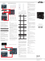
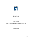
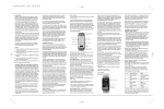
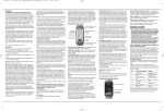
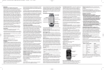
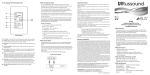
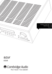
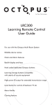
Introduction
Thank you for choosing Harman Kardon! The ABH 4000 Expansion Hub
will enable you to extend the capabilities of an A-BUS®-based multiroom
system to four zones and up to eight or more rooms, with a Harman Kardon®
AB 2 amplified module as the control point. A few simple connections to a
Harman Kardon A-BUS-equipped product, or a source device’s multiroom,
tape or line-level output, will enable you to add the power and simplicity of
A-BUS to your home.
We strongly recommend that you read this instruction sheet carefully before
installing your new ABH 4000. If you do not have experience installing in-wall
electrical and telecommunications components, you are advised to consult
with a qualified low-voltage contractor or custom installer.
If you have any questions about this product, its installation or its operation,
please contact your retailer or custom installer. They are your best source
of product information.
The ABH 4000 will add to your listening pleasure by distributing sound throughout your home with the level of performance for which Harman Kardon has been
famous for more than fifty years.
and connectors that will be attached to the ABH 4000 so that severe angle
bends of connecting cables are avoided.
be convenient to connect this output to the compatible IR input of an A/V receiver
without A-BUS.
The wiring used to connect the ABH 4000 to the A-BUS-equipped product and
A-BUS modules in remote rooms may be Category 5 or higher wiring. Consider
any specific electrical or building code requirements for riser or plenum use. The
system speaker wiring should also be in-wall-rated as required, and may not
exceed 2 square millimeters. To simplify wiring, use two pairs of (4 x 14)
CL-3-rated in-wall wiring and run a single cable from each amplified A-BUS
module to both locations. One pair will be used to connect the first speaker and
the other will continue to the second speaker.
IR Indicator: This LED will flash to confirm that an IR signal is being passed
through the ABH 4000. This signal may originate from a remote A-BUS module
in any of the four zones.
What Is Included
Your ABH 4000 should be packed with the following items. If any of the below
are missing, please contact Harman Kardon customer service.
• ABH 4000 Expansion Hub
• One Power Supply
• One AC Power Cord
• RJ-45 Connection Jumper Cable
Audio Inputs
Routed IR
Outputs
A-BUS
Outputs
Audio Outputs
• Simple connection to any A-BUS-equipped Harman Kardon receiver and
many other A-BUS products
• Analog audio inputs and outputs, along with IR outputs, enable use with
non-A-BUS products as well
• Adds A-BUS capability to multiroom systems with only a single Category 5
cable run to each remote module
Control Link Input: Connect this jack to the Control Link Output on another
ABH 4000 to expand the total number of rooms in your system.
• Allows for up to four separate zones, each distributing an independent
source device
NOTES:
• Two banks available, allowing up to two rooms per zone
• Expandable to up to 16 zones using additional ABH 4000 hubs
• Twelve-volt trigger output may be used to power on source devices
A-BUS
Inputs
Trigger
Output
Common
IR Output
Status IR Indicator
Indicator
Control
Link Output
Control
Link Input
Power
Inputs
Power
Indicators
• Designed for easy mounting on wire back-boards, or for shelf placement
ABH 4000 Connections and Indicators
IMPORTANT SAFETY AND INSTALLATION INFORMATION!
Wire Separations
Audio Inputs: When the ABH 4000 is used with a receiver or source devices
without an A-BUS jack, connect the analog audio outputs from the receiver
or source to one set of these input jacks. Up to four independent devices may
be connected to the Audio Inputs, each of which may be selected by any one
or more of the ABH 4000’s four output zones.
NOTES:
Category 5 wiring systems must be installed to minimize the possibility of accidental
contact with hazardous power and lighting wiring. Never place Category 5 wiring
near bare power wires or lightning rods, antennas, transformers, steam or hot
water pipes, or heating ducts. Never place Category 5 wire in any conduit, box,
channel, duct or other enclosure containing power or lighting circuits of any
type. Always provide adequate separation between Category 5 wiring and other
electrical wiring according to code. When in doubt about separation distances,
the “Rule of Sixes” can be used. This rule requires 6 feet of separation between
Category 5 wiring and open high-voltage wiring, lightning grounding wire or
grounding rods. It requires 6 inches of separation from all other high-voltage wiring,
unless in conduit. Of course, local building and electrical codes always govern.
Cutting and Drilling
Always observe all applicable safety rules for in-wall wiring. Be extremely careful
not to cut through or drill into concealed wiring or pipes. Make a small inspection
opening before cutting or drilling.
Additional Installation Information
Common wire-splicing techniques may cause the wire to break, resulting
in poor circuit integrity. This can cause interference and result in poor system
performance.
Dust or dirt can cause special problems on wiring contacts. Be sure all contacts
are clean and that all parts are installed correctly to protect them from dust
and dirt.
Your new Harman Kardon ABH 4000 A-BUS Expansion Hub has been designed
only for use with A-BUS products. Do not connect the RJ-45 jacks to any other
device.
Make sure to follow all instructions when preparing wiring for use with the
ABH 4000 Expansion Hub and associated equipment. Failure to do so may
result in a potential safety hazard, including possible danger to persons and/or
equipment.
If you will be running RJ-45 cable through a ventilation plenum, use plenum-rated
cable to comply with NEC and local electrical codes. Failure to do so may result
in a potential fire or safety hazard.
Installation Planning
The ABH 4000 may be placed flat on a shelf or mounted to a wire back-board
using standard wood screws and the keyhole notches on its outer edges. The
unit’s power supply must be placed on a shelf and should not be attached to a
back-board. When planning an installation, allow sufficient clearance for all wires
Audio Outputs: The ABH 4000 passes signals from the Audio Inputs straight
through to the corresponding Audio Outputs for sharing with other devices, such
as an A/V receiver.
Control Link Output: If you are using more than one ABH 4000 in your
system to add additional rooms, connect one end of a jumper cable with RJ-45
connectors to this jack. Connect the other end of the jumper cable to the Control
Link Input on the next ABH 4000. To expand the system using an ABH 4 or
other hub, connect one of the ABH 4000’s A-BUS Outputs to the expansion
input on the ABH 4 or other hub. You may use one of the Bank B A-BUS
Outputs for this purpose without connecting a power supply.
Features
• Infrared (IR) commands from each zone are routed separately, allowing for
more than one source device of a given type
A-BUS Outputs: These jacks are the communications link between the remote
A-BUS modules and the ABH 4000, carrying audio signals and power to the
A-BUS modules, and IR or other control commands from the A-BUS modules to
the ABH 4000 and products connected to it. Connect a Category 5 cable from
each remote A-BUS module to these outputs using standard RJ-45 connectors
with cabling wired in compliance with the TIA 568A standard. When expanding
the system using single-source A-BUS devices other than additional ABH 4000
hubs, connect the devices to one of the A-BUS Outputs. If the device is powered
(e.g., an ABH 4 hub), it may be connected without using the ABH 4000’s power
supply.
• When any source is selected, the ABH 4000 hub and all A-BUS modules
connected to it that do not have individual power on/off capabilities will turn on.
• Audio Input 1 is wired in parallel with the A-BUS Input. If the A-BUS input is
connected directly to an A-BUS-equipped device, no connections should be
made to Audio Input 1.
A-BUS Input: This jack connects to the device that is providing the A-BUS
system source that feeds the A-BUS modules used with this ABH 4000. In most
applications, the connection will be to the A-BUS port on an A-BUS-equipped
Harman Kardon receiver. Do not connect the A-BUS Input to the Control Link
Output of another ABH 4000, or the expansion output of a Harman Kardon
ABH 4 or other A-BUS expansion hub. Connect multiple hubs, using the Control
Link Input and Output. The connection should be made using a standard
TIA 568A RJ-45 jumper cable.
Status Indicator: This LED will light when the ABH 4000 is activated. In most
cases, it will light when a Harman Kardon A-BUS-equipped product connected
to the ABH 4000 is turned on, or when a command is received from any of
the four zones. When the ABH 4000 is used with non-A-BUS products, the
Status Indicator will light when any of the four sources is selected. When the
Status Indicator is lit, a 12V signal is available at the Trigger Output.
Trigger Output: The Trigger Output may be used to turn on compatible devices
when the ABH 4000 is activated, as indicated by the Status Indicator.
Routed IR Outputs: When the ABH 4000 is used with non-A-BUS sources,
these jacks may be used to route IR signals to devices with compatible remote
IR inputs, or to optional remote IR emitters. The emitters should be placed over
the IR receiver in the source components to be controlled. This enables a remote
to control source components, from the room where an A-BUS module is
installed, when the module includes an IR receiver.
NOTE: The Routed IR Outputs will only emit commands from the zone that has
selected the source, allowing connection of more than one source device of the
same type to the ABH 4000 without concern that commands issued from one
zone will have undesired effects on playback in another zone. However, if the
source devices are physically near each other, you may wish to use light-blocking caps with the emitters to prevent cross-communication.
Common IR Output: This output passes control commands from all zones to
compatible non-A-BUS devices, allowing control of common components. It may
• The Control Link Input and Output are used to pass control data between
ABH 4000 expansion hubs in an A-BUS system. Do not connect the Control
Link Input or Output to any device other than an ABH 4000.
• Do not connect an ABH 4000 to the Expansion Output of an ABH 4 hub,
as the ABH 4000 will not operate correctly.
questions or doubt about the ability of the wall surface to properly support the
weight of the ABH 4000, consult a properly trained installer before proceeding.
• When the anchor is installed, place a screw through the slot on either side
of the ABH 4000, and tighten the screw most of the way into the anchor.
• Slip the ABH 4000 so that it slides down the keyhole notch of the slot, and
tighten it securely.
Connections to an A-BUS-Equipped Product (see Figure 1)
Step One: Connect the ABH 4000 to the Receiver
Connect one end of the included RJ-45 jumper cable to the A-BUS Input
and the other end to the A-BUS jack on the rear panel of your Harman Kardon
receiver.
Step Two: Connect the A-BUS Modules
Connect the RJ-45 jacks on the Cat. 5 cabling that runs to the remote room
modules to the A-BUS Outputs. Make certain that the connector is wired in
accordance with the standard TIA 568A color-coding. Connect the A-BUS modules
in the remote rooms to the Cat. 5 cable in accordance with the color-coding on
the module. Install loudspeakers in each remote room and connect them to the
A-BUS modules, following the manufacturers’ instructions.
NOTE: To control the system from the remote zones, or when a non-A-BUSequipped source is used, at least one A-BUS module in each zone must have
an infrared receiver or the ability to control the ABH 4000 (i.e., power the
system on or off and select a source). The Harman Kardon AB 2 module is
equipped with both an IR receiver and built-in capability to control the ABH 4000.
The Harman Kardon AB 1 module has the necessary IR receiver. We recommend
installing at least one AB 1 or AB 2 module in each zone.
Step Three: Connect the AC Power Supply
In open-plan areas or adjoining rooms, single-source expansion may be required
so that a common music source is heard in the area. Connect an RJ-45 jumper
cable from one of the ABH 4000’s A-BUS Outputs to the Expansion Input of
an ABH 4 single-source hub. If connected to a Bank B Output, no power supply
is required for Bank B. Complete the system installation by following Steps Two
and Three.
NOTE: Do not connect an ABH 4 hub to the ABH 4000’s Control Link Output,
and do not connect an ABH 4000 hub to an ABH 4’s Expansion Output.
Connections to a Non-A-BUS Product (see Figure 2)
The ABH 4000 may also be used to bring the benefits of A-BUS technology
to virtually any audio system with a few additional steps to connect an audio feed
and to install infrared emitters to control the source equipment. You may wish to
have this installation completed by a trained installer who is familiar with A-BUS
and audio/video systems integration.
Step One: Connect Audio Sources
Connect the audio outputs of up to four sources, using standard audio interconnect
cables (not included) from the Audio Inputs on the ABH 4000 to the analog
audio outputs of each source device, such as a preamplifier, receiver, surround
processor, CD player, tuner or any other device equipped with line-level analog
audio outputs. Although the Audio Inputs on the ABH 4000 are numbered
1 through 4, these numbers do not correspond to the output zones, and one
may select any of the four sources for playback in any of the four A-BUS
Output zones. The numbered Audio Outputs correspond to the Audio Inputs,
not the zones.
Connect the source devices as follows, to allow for the simple source control
available with the AB 2 (as described in the Operation section):
Connect the AC Power Supply furnished with the ABH 4000 to Power Input A.
If you have connected A-BUS modules to Bank B of the A-BUS Outputs, connect a second AC Power Supply (not included) to Power Input B. Plug each
AC power cord into the socket on its Power Supply. Do not connect the power
cords to an AC outlet at this time.
Source 1: Tuner or A/V receiver
Optional Step Four: System Expansion
NOTE: When using an A-BUS-equipped Harman Kardon A/V receiver, do
not use the Source 1 Audio inputs. Source 1 is the AVR connected to the
ABH 4000’s A-BUS Input.
Power Inputs: Connect the 2.5mm DC plug at the end of the ABH 4000
power supply to Power Input A, to power Bank A of the system. If you are connecting modules to Bank B of the system, a second power supply (not included)
must be connected to Power Input B. Do not use a power supply other than one
recommended by Harman Kardon, to avoid damaging the ABH 4000 or other
system components.
Up to three additional single-source or multisource hubs may be connected
to the system. A single-source hub, such as the Harman Kardon ABH 4, is
connected to only one source device, with the audio and control signals distributed to the remote zones. A multisource hub, such as the ABH 4000, may be
connected to up to four source devices, with the signals distributed to up to
four independent zones.
Power Indicators: These LEDs will light to indicate that Bank A or Bank B of the
ABH 4000 is connected to a power source that enables the remote modules and
the infrared relay system to operate. This power source may be either a connection
to an A-BUS product, the ABH 4000’s power supply or through a connection to
another ABH 4000. The ABH 4000’s external power supply must be connected
in order for it to power multiple remote modules.
Multisource Hubs
INSTALLATION AND CONNECTION
Single-Source Hubs
Up to four ABH 4000 hubs may be connected to create 16 independent
zones with two room outputs per zone. To expand the audio signal, connect
the Audio Outputs to the next hub’s audio inputs. To expand the control data,
connect an RJ-45 jumper cable from the Control Link Output to the Control
Link Input on the next hub. Complete the system installation by following Steps
Two and Three above.
Important Safety Note
Before beginning the installation process, turn off all electronics products in
the system and disconnect them from their A/V power connection. This avoids
the possibility of accidental activation that could possibly damage the equipment
or cause personal injury. Do not turn on the equipment until instructed.
Source 2: CD player or changer
Source 3: DVD player
Source 4: Any source device
Steps Two and Three are the same as in the Connections to an
A-BUS-Equipped Product section.
Step Four: Connect the IR Outputs to the Source Devices
For non-A-BUS sources, infrared (IR) signals are used to control the sources
remotely from each local A-BUS module. It is recommended that you install
A-BUS modules with built-in IR receivers, such as the Harman Kardon AB 1
and AB 2, so that you may operate each of your sources.
When possible, connect the IR Outputs directly to compatible IR inputs on each
source device.
Each Routed IR Output should be connected to the IR input (or an IR emitter
placed over the IR sensor) of the source device connected to the correspondingly
A-BUS® Modules (Harman Kardon AB 1 and AB 2 shown)
The ABH 4000 may be used in two modes of operation. The installation
process will vary, according to which option you select.
• When used in conjunction with an A-BUS-equipped Harman Kardon product,
the ABH 4000 provides the power that enables up to eight remote rooms to
be equipped with A-BUS modules such as the Harman Kardon AB 1 or AB 2,
with more room installations possible through the use of additional ABH 4000
or ABH 4 hubs.
• The ABH 4000 may also be used with any receiver, preamplifier or surround
processor that has an analog audio output to send the selected source to
A-BUS modules installed in remote rooms. Alternatively, up to four source
devices may be connected to the ABH 4000 to create a multiroom audio
system with up to four independent zones.
Step Two
A-BUS-Equipped Product
Mounting the ABH 4000 (optional)
The ABH 4000 may be mounted on a wall, using the screw slots provided on
the sides of the unit, or it may be placed on any flat surface.
Step Three
Step One
• To mount the ABH 4000 to a wall, first make certain that there is sufficient
clearance on all sides for any cables that will be attached.
• While holding the ABH 4000 to the wall, trace the outline of the slots on the
“wings” on the left and right sides of the ABH 4000 onto the wall.
• Drill a pilot hole and install an anchor or retaining socket sufficient to accommodate
a #10 pan-head Phillips-type wood screw that is at least long at each side,
under the circular part of the tracing. If possible, attach at least one side of the
ABH 4000 to a wall stud, instead of using a wall anchor. If you have any
ABH 4000
Figure 1 – Connecting the ABH 4000 to an A-BUS-equipped product
Figure 5 – ABR remote (included with AB 2)
The AB 2 keypad is operated using “long” and “short” button presses to activate
different commands using the same button. A short press is released quickly. For a
long press, continue to hold the button for about three seconds before releasing it.
Button Name
ABH 4000
AVR
Figure 2 – Connecting the ABH 4000 to a non-A-BUS-equipped product
numbered Audio Input. The ABH 4000 will route signals from any output zone
that has selected that source device directly to that device. This allows you to
use two sources with the same control code set, such as two CD players, with
control commands affecting only the desired device.
Use the Common IR Output when all devices use independent code sets
to simplify control through a receiver or other central component. All control
commands received from all zones are output through the single Common
IR Output. Connect it to a receiver’s IR input, or connect an IR emitter that is
placed over the receiver’s IR sensor, as shown in Figure 3.
Optional Step Five: System Expansion
See Optional Step Four in the Connections to an A-BUS-Equipped
Product section, to expand the system using additional hubs.
NOTE: The following steps provide additional options that extend the flexibility of
your A-BUS system. If you are not familiar with audio/video systems installations,
you may wish to have them completed by a properly trained installer.
Optional Step Six: Trigger Connection
Connect the Trigger Output to a component or power relay that turns on in
response to a steady-state 12-volt trigger signal. When the ABH 4000 hub
is turned on, the trigger signal will turn on any components connected to the
Trigger Output, or components that are plugged into a power strip connected
to the Trigger Output. When the ABH 4000 is turned off, the components will
also turn off.
Optional Step Seven: Connect IR Emitters
If you are not using direct IR control connections to “IR In” jacks on non-A-BUS
products and wish to control a source product, connect an optional IR emitter
to the Routed or Common IR Outputs and place it over the IR sensor on
the front panel of the unit to be controlled.
Operation
There are no user controls on the ABH 4000; it is controlled using an AB 2
keypad or the remote suppled with the AB 2.
After checking the connections, plug the AC power cord from the ABH 4000’s
Power Supply A into a non-switched AC outlet. If modules have been connected
to Bank B for any zone, a second power supply (sold separately) is required and
must be plugged into Power Supply B and a second non-switched AC outlet.
The power supply is designed specifically for use with the ABH 4000. Do not
substitute another power supply.
When the ABH 4000 is used with an A-BUS-equipped product, the A-BUS
modules in the remote room operate as if they were connected directly to the host
receiver. No further controls are needed. Follow the instructions included with the
A-BUS modules for operation information.
When the multiroom system of a Harman Kardon A-BUS-equipped product is
turned on or when a source is selected from one of the zones, the ABH 4000
will also be activated.
When a non-A-BUS source is used, the ABH 4000 turns on when a source is
selected from one of the zones.
The Status Indicator will light, and the Trigger Output will activate, signaling any
devices connected to it to turn on as well.
Use the second-zone remote included with an A-BUS-equipped product to
operate the sources and the system, as described in the product’s manual. For
simple functions, when an AB 2 keypad is installed, it may be used to operate
the sources and system as described below. The ABR remote included with the
AB 2 may also be used, as described in the Function Table.
Figure 3 – Connecting the IR outputs to non-A-BUS products
ABH 4000
ABR Remote
(Short Press on AB 2)
Turns on an A-BUS-equipped
product and selects tuner as
source. Subsequent presses
toggle tuner band.
CD
Long Press on AB 2
Turns on an A-BUS-equipped
product, selects The Bridge
as source and if an iPod is
docked in The Bridge, begins
play. If iPod was playing, it
will pause. Press again if no
audio is heard.
If CD is already playing,
issues Disc Skip command.
Turns on CD player and
issues Play/Pause command.
If player is paused, it will begin
playing. If player was playing,
it will pause. Press again if no
audio is heard.
DVD
Turns on DVD player and
If DVD was turned on (LED
begins play.
on AUX button is lit), issues
DVD Play command.
MP3
ABH 4000 selects Source 4. ABH 4000 selects Source 4.
Power Off
Mutes or unmutes the AB 2; If Source 1 is playing, turns
only that AB 2 is affected.
off an A-BUS-equipped
product. If another source is
playing, AVR remains on and
ABH 4000 is turned off.
Skip (AB 2 only) Depends on current source:
Depends on current source:
Tuner – Preset Up
Tuner – Preset Down
CD – Track Skip Up
CD – Track Skip Down
DVD – Next Chapter
DVD – Previous Chapter
Source 4 – no action
Source 4 – no action
Volume Up
Volume Up
Volume Up
Volume Down
Volume Down
Volume Down
System Off
(ABR remote
only)
If Source 1 is playing, turns
off an A-BUS-equipped
product. If another source is
playing, AVR remains on and
ABH 4000 is turned off.
Not applicable
Function Table
Source Selection
When an AB 2 is present or using the ABR remote, press any of its four source
buttons to select that source. If the AB 2 and the ABH 4000 are turned off, they
will turn on, and if the source is connected to the Trigger Output, it will be activated
and play will begin. The AB 2’s power indicator LED will light to indicate that the
system is turned on, and the LED indicator for the selected source will light on
the AB 2.
To select The Bridge as the source on an A-BUS-equipped Harman Kardon
product when The Bridge is connected, press and hold the AVR Button on the
AB 2, or press the appropriate source selector on the second-zone remote
included with the AVR.
NOTES:
• The functions selecting The Bridge or a CD player as the source issue the
Play/Pause command. However, the source’s status is not communicated back
to the AB 2, which always issues the same command when the button is
pressed. If the source is selected and no audio is heard, press the button again.
• Some older CD players and other source devices require separate commands
for the Play and Pause functions. These devices may not operate as described
when connected to Source 2.
• It is preferable to connect all of the sources to an A-BUS-equipped Harman Kardon
product, and select and operate them using the second-zone remote included
with the product.
Source Control
If the source is an A-BUS-equipped product, or if it is connected to the Routed
or Common IR Outputs using either a wired connection or an IR emitter, the AB 2
or its remote will provide simple control functions as described in the table above,
ABH 4000
Figure 4 – AB 2 module
including Play, Pause, Preset Up/Down, Track Skip Up/Down, Chapter
Next/Previous and Disc Skip.
For more sophisticated control, aim a properly programmed remote control, such
as the second-zone remote included with an A-BUS-equipped Harman Kardon
receiver, at the IR Receiver on the AB 1 or AB 2 (or other A-BUS module if so
equipped), and control commands will be passed directly to the source device.
Volume Control
Volume is controlled locally for each room of each zone using its A-BUS module.
On the AB 1, tap the Volume Down Button to temporarily mute the audio, and
tap the Volume Up Button to restore audio. For the AB 2, each short press of
the Power Off Button toggles between the muted and unmuted modes.
NOTE: When the system is turned off, all modules will reset to their minimum
volume.
Powering the System Off
Press and hold the Power Button on an AB 2 to turn off the ABH 4000 and
the entire system, if the Harman Kardon A-BUS-equipped receiver is in tuner
mode. If another source is playing, the AVR will remain on – for example, if
someone is watching a DVD in the main listening room. However, the ABH 4000
will turn off, which terminates the trigger signal and thus turns off any sources
connected to the Trigger Output.
NOTES:
• If you wish to fully power down the system, select the tuner as the source
just before pressing and holding the Off Button.
• If you only wish to power down the ABH 4000, make sure that any sources
being used by others are not connected to the Trigger Output, or they will
turn off.
LED Indicators
The three LED indicators on the ABH 4000 signify the following operational modes:
• The Status Indicator lights when the system is activated either by connection
to an A-BUS-equipped product that is turned on, when a source is selected,
or when the system is turned on from a remote zone. This light also indicates
that the Trigger Output is active.
• The Power Indicators light when an AC Power Supply is connected to either
power input on the ABH 4000 (for Bank A or B) and/or when a connection
is made between the ABH 4000 and an A-BUS-equipped product. This light
does not indicate that the system is powered on; that is indicated by the
Status Indicator.
• The IR Talk Indicator flashes whenever an IR command is transmitted through
the system.
Troubleshooting Guide
If the remote A-BUS modules do not operate at all:
• Verify all connections between the remote modules and the ABH 4000.
• Check the RJ-45 connection between the ABH 4000 and the host product.
• Check the AC power connection at both the ABH 4000’s Power Jacks and
on the Power Supplies.
If the remote module’s status LED is lit but there is no sound:
• Make certain that an active source has been selected on the host receiver.
• Check the RJ-45 connection between the ABH 4000 and the A-BUSequipped host product.
• Check the audio connections between the ABH 4000 and the non-A-BUS
host product.
• When the ABH 4000 remote or the AB 2 keypad is in use and the CD player
or The Bridge has been selected, repeat the command, as it issues Play and
Pause and depends on the current status of the source.
For additional troubleshooting information and updated operational and
installation hints, please visit the Product Support section of the Harman Kardon
Web site at www.harmankardon.com.
®
A-BUS® Modules (Harman Kardon AB 1 and AB 2 shown)
4-Zone/8-Room Expansion Hub
for A-BUS Applications
Non-A-BUS Sources
Specifications
ABH 4000 Dimensions (D x W x H):
83mm x 184mm x 30mm (3-5/16" x 7-3/16" x 1-3/16")
Weight: 410g (0.9 lb)
Power Supply Dimensions (D x W x H):
70mm x 151mm x 36mm (2-13/16" x 5-15/16" x 1-7/16")
Weight: 450g (1 lb)
Power Supply Input: 108V – 264V AC, 115 watts
Power Supply Output: 24-volt, 4-amp supply included
Trigger Output: 12 volts, 100ma
Wiring protocol for A-BUS connections: TIA wiring specification for TIA 568A
250 Crossways Park Drive, Woodbury, New York 11797
516.255.4545 Fax: 516.682.3583
© 2008 Harman International Industries, Incorporated. All rights reserved.
Part No. ABH-4000-OM
Harman Kardon is a trademark of Harman International Industries, Incorporated, registered in the United States
and/or other countries. Designed to Entertain is a trademark of Harman International Industries, Incorporated.
A-BUS is a registered trademark of LeisureTech Electronics Pty Ltd.
All features and specifications are subject to change without notice.