1
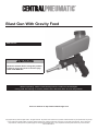
Blast Gun With Gravity Feed
Item 95793
Read this material before using this product.
Failure to do so can result in serious injury.
Save this manual.
When unpacking, make sure that the product is intact and undamaged.
If any parts are missing or broken, please call 1-800-444-3353 as soon as possible.
Visit our website at: http://www.harborfreight.com
Copyright© 2007 by Harbor Freight Tools®. All rights reserved. No portion of this manual or any artwork contained herein may be reproduced in any shape
or form without the express written consent of Harbor Freight Tools. Diagrams within this manual may not be drawn proportionally. Due to continuing
improvements, actual product may differ slightly from the product described herein. Tools required for assembly and service may not be included.
Manual Revised 11i
Save This Manual
Keep this manual for the safety warnings and
precautions, assembly, operating, inspection,
maintenance and cleaning procedures. Write the
product’s serial number in the back of the manual near
the assembly diagram (or month and year of purchase
if product has no number). Keep this manual and the
receipt in a safe and dry place for future reference.
Safety Alert Symbol
and Signal Words
In this manual, on the labeling, and all other
information provided with this product:
This is the safety alert symbol. It is
used to alert you to potential personal
injury hazards. Obey all safety
messages that follow this symbol
to avoid possible injury or death.
DANGER indicates a hazardous situation which, if
not avoided, will result in death or serious injury.
Important Safety
Instructions
Instructions Pertaining to a
Risk of Fire, Electric Shock,
or Injury to Persons
WARNING – When using tools, basic precautions
should always be followed, including the following:
Work Area
a. Keep the work area clean and well lighted.
Cluttered benches and dark areas increase the
risks of electric shock, fire, and injury to persons.
b. Do not operate the tool in explosive atmospheres,
such as in the presence of flammable liquids,
gases, or dust. The tool is able to create sparks
resulting in the ignition of the dust or fumes.
c. Keep bystanders, children, and visitors away
while operating the tool. Distractions are able
to result in the loss of control of the tool.
Personal Safety
WARNING indicates a hazardous situation which, if
not avoided, could result in death or serious injury.
CAUTION, used with the safety alert symbol,
indicates a hazardous situation which, if not
avoided, could result in minor or moderate injury.
NOTICE is used to address practices
not related to personal injury.
a. Stay alert. Watch what you are doing and
use common sense when operating the tool.
Do not use the tool while tired or under the
influence of drugs, alcohol, or medication.
A moment of inattention while operating the
tool increases the risk of injury to persons.
b. Do not overreach. Keep proper
footing and balance at all times.
Proper footing and balance enables better
control of the tool in unexpected situations.
c.
Use safety equipment.
Wear a NIOSH‑approved respirator and
heavy‑duty work gloves during use.
Non-skid safety shoes and a hard hat
must be used for the
applicable conditions.
d.
Always wear eye protection.
Wear ANSI-approved safety goggles.
e.
Always wear hearing protection
when using the tool.
Prolonged exposure to high intensity
noise is able to cause hearing loss.
CAUTION, without the safety alert symbol, is used
to address practices not related to personal injury.
Page 2
For technical questions, please call 1-800-444-3353.
SKU 95793
Tool Use and Care
a. Do not force the tool. Use the correct tool for the
application. The correct tool will do the job better
and safer at the rate for which the tool is designed.
Symbols and Specific Safety Instructions
Symbol Definitions
b. Disconnect the tool from the air source
before making any adjustments, changing
accessories, or storing the tool. Such preventive
safety measures reduce the risk of starting the
tool unintentionally. Turn off and detach the air
supply, safely discharge any residual air pressure,
and release the throttle and/or turn the switch to
its off position before leaving the work area.
Symbol
c. Store the tool when it is idle out of reach
of children and other untrained persons.
A tool is dangerous in the hands of untrained users.
NPT
National pipe thread, tapered
NPS
National pipe thread, straight
d. Check for misalignment or binding of moving
parts, breakage of parts, and any other condition
that affects the tool’s operation. If damaged,
have the tool serviced before using. Many accidents
are caused by poorly maintained tools.
There is a risk of bursting if the tool is damaged.
e. Use only accessories that are identified by the
manufacturer for the specific tool model. Use of
an accessory not intended for use with the specific
tool model, increases the risk of injury to persons.
a. Tool service must be performed only
by qualified repair personnel.
b. When servicing a tool, use only identical
replacement parts. Use only authorized parts.
Air Source
Never connect to an air source that is
capable of exceeding 200 psi.
Over pressurizing the tool may cause
bursting, abnormal operation, breakage
of the tool or serious injury to persons.
Use only clean, dry, regulated compressed air at the
rated pressure or within the rated pressure range as
marked on the tool. Always verify prior to using the
tool that the air source has been adjusted to the rated
air pressure or within the rated air-pressure range.
b. Never use oxygen, carbon dioxide, combustible
gases or any bottled gas as an air source
for the tool. Such gases are capable of
explosion and serious injury to persons.
Save these
instructions.
SKU 95793
Pounds per square inch of pressure
CFM
Cubic Feet per Minute flow
SCFM
Cubic Feet per Minute flow
at standard conditions
WARNING marking
concerning Risk of Eye Injury.
Wear ANSI‑approved eye protection.
WARNING marking concerning Risk of
Hearing Loss. Wear hearing protection.
WARNING marking concerning
Risk of Respiratory Injury. Wear
NIOSH‑approved respirator.
WARNING marking concerning
Risk of Explosion.
Service
a.
PSI
Property or statement
Specific Safety Instructions
1. The warnings and precautions discussed in this
manual cannot cover all possible conditions and
situations that may occur. It must be understood
by the operator that common sense and caution
are factors which cannot be built into this
product, but must be supplied by the operator.
2. Do not exceed maximum 90 PSI.
3. Avoid unintentional starting. Prepare to
begin work before turning on the tool.
4. Do not leave the tool unattended when it is plugged
into an compressor. Release the Trigger, and
unplug the tool from its air source before leaving.
5. Do not point the Nozzle at a human or an animal.
6. Use clamps (not included) or other
practical ways to secure and support
the workpiece to a stable platform.
7. This product is not a toy.
Keep it out of reach of children.
For technical questions, please call 1-800-444-3353.
Page 3
8. WARNING: This product, when used for abrasive
blasting and similar applications, produces chemicals
known to the State of California to cause cancer and
birth defects (or other reproductive harm).
(California Health & Safety Code § 25249.5, et seq.)
9. WARNING: The brass components of this
product contain lead, a chemical known to
the State of California to cause birth defects
(or other reproductive harm).
(California Health & Safety code § 25249.5, et seq.)
10. Obey the manual for the air compressor
used to power this tool.
11. Install an in-line shutoff valve to allow
immediate control over the air supply in an
emergency, even if a hose is ruptured.
12. If any abnormal vibration occurs,
stop use immediately.
13. The warnings and precautions discussed in this
manual cannot cover all possible conditions and
situations that may occur. It must be understood
by the operator that common sense and caution
are factors which cannot be built into this
product, but must be supplied by the operator.
Silicosis and Aluminum
Oxide Warnings
Warning: Abrasive blasting with sand containing
crystalline silica can cause serious or fatal respiratory
disease. Exposure to crystalline silica may cause
silicosis (a serious lung disease), cancer and death.
Exposure to aluminum oxide (a dust generated from
material removing processes) can result in eye, skin
and breathing irritation. Always use a NIOSH (National
Institute for Occupational Safety and Health) approved
respirator and safety goggles. Avoid skin exposure.
Proper ventilation in the work area is required. Read
and understand the 10 recommended measures below
to reduce crystalline silica exposures in the workplace
and prevent silicosis and silicosis related deaths.
Page 4
NIOSH recommends the following measures to
reduce crystalline silica exposures in the workplace
and prevent silicosis and silicosis-related deaths:
1. Prohibit silica sand (or other substances
containing more than 1% crystalline silica)
as an abrasive blasting material and
substitute less hazardous materials.
2. Conduct air monitoring to measure worker exposures.
3. Use containment methods such as blast-cleaning
machines and cabinets to control the hazard
and protect adjacent workers from exposure.
4. Practice good personal hygiene to avoid
unnecessary exposure to silica dust.
5. Wear washable or disposable protective clothes
at the work site. Shower and change into clean
clothes before leaving the work site to prevent
contamination of cars, homes and other work areas.
6. Use respiratory protection when source controls
cannot keep silica exposures below the NIOSH REL.
7. Provide periodic medical examinations for all
workers who may be exposed to crystalline silica.
8. Post signs to warn workers about the hazard and to
inform them about required protective equipment.
9. Provide workers with training that includes
information about health effects, work practices
and protective equipment for crystalline silica.
10. Report all cases of silicosis to State health
departments and to OSHA or the Mine Safety
and Health Administration (MSHA).
Save these
instructions.
For technical questions, please call 1-800-444-3353.
SKU 95793
Note: An oiler system should not be used
with this tool. The oil will mix with the material
being propelled, causing poor results.
Functional Description
Specifications
Max. Air Pressure
90 PSI
Air Inlet
1/4 IN. - 18 NPT
Hopper Capacity
20 OZ.
Air Consumption
7 CFM @ 90 PSI
Initial Tool Set Up/Assembly
Read the entire Important
Safety Information section at the
beginning of this manual including
all text under subheadings therein
before set up or use of this product.
Note: For additional information regarding the
parts listed in the following pages, refer to the
Assembly Diagram near the end of this manual.
Note: This air tool may be shipped with a protective plug
covering the air inlet. Remove this plug before set up.
Air Supply Setup
To prevent serious injury
from explosion:
Use only clean, dry, regulated, compressed
air to power this tool. Do not use oxygen,
carbon dioxide, combustible gases, or any other
bottled gas as a power source for this tool.
1. To attach an air hose - 3/8″ - 18 NPT (not included) to
the Blast Gun, wrap approximately 3″ of pipe thread
sealer tape (not included) around the male threads
at the end of the air hose. Then, firmly tighten the
air hose onto the Air Inlet (2) of the Blaster Gun.
2. Incorporate a filter, regulator with pressure gauge,
in-line shutoff valve, and quick coupler for best
service, as shown on Figure A on page 6 and
Figure B on page 7. An in-line shutoff ball
valve is an important safety device because
it controls the air supply even if the air hose
is ruptured. The shutoff valve should be a
ball valve because it can be closed quickly.
SKU 95793
3. Attach an air hose to the compressor’s air outlet.
Connect the air hose to the air inlet of the tool.
Other components, such as a coupler plug
and quick coupler, will make operation
more efficient, but are not required.
WARNING! To prevent serious injury
from accidental operation:
Do not install a female quick coupler on the tool.
Such a coupler contains an air valve that will
allow the air tool to retain pressure and operate
accidentally after the air supply is disconnected.
Note: Air flow, and therefore tool performance, can
be hindered by undersized air supply components.
4. The air hose must be long enough to reach
the work area with enough extra length to
allow free movement while working.
5. Close the in-line shutoff valve between
the compressor and the tool.
6. Turn on the air compressor according to
the manufacturer’s directions and allow it
to build up pressure until it cycles off.
7. Adjust the air compressor’s output regulator so
that the air output is enough to properly power
the tool, but the output will not exceed the tool’s
maximum air pressure of 90 PSI at any time.
Adjust the pressure gradually, while checking the
air output gauge to set the right pressure range.
8. Inspect the air connections for leaks.
Repair any leaks found.
9. If the tool will not be used at this time, turn off and
detach the air supply and safely discharge any
residual air pressure to prevent accidental operation.
Note: Residual air pressure should not be present after
the tool is disconnected from the air supply. However,
it is a good safety measure to attempt to discharge
the tool in a safe fashion after disconnecting to ensure
that the tool is disconnected and unpowered.
For technical questions, please call 1-800-444-3353.
Page 5
Page 6
For technical questions, please call 1-800-444-3353.
SKU 95793
A
B
C
D
E
F
G
H
Air Hose
Filter
Regulator
Lubricator (optional)
Coupler and Plug
Leader Hose (optional)
Air Cleaner / Dryer (optional)
Air Adjusting Valve (optional)
Description
Non-lubricated
Tools
A
Lubricated
Tools
B
B
C
C
A
Function
A
E
E
F
H
Connects air to tool
Prevents dirt and condensation from damaging tool or work piece
Adjusts air pressure to tool
For air tool lubrication
Provides each connection
Increases coupler life
Prevents water vapor from damaging work piece
For fine tuning airflow at tool
G
D
Figure A: Portable Air Supply Setup
SKU 95793
For technical questions, please call 1-800-444-3353.
Page 7
B
A
A
B
C
D
E
F
G
H
I
J
K
L
M
N
O
F
Description
F
E
C
C
H
H
J
I
K
J
L
Function
L
M
M
O
N
For noise and vibration reduction
Secures air compressor in place
Isolates sections of system for maintenance
For vibration reduction
Distributes air to branch lines
To drain moisture from system
Brings air to point of use
Prevents dirt and condensation from damaging tool or work piece
Prevents water vapor from damaging work piece
Adjusts air pressure to tool
For air tool lubrication
Connects air to tool
Provides each connection
For fine tuning airflow at tool
Increases coupler life
Non-lubricated
Tools
Vibration Pads
Anchor Bolts
Ball Valve
Isolation Hose
Main Air Line - 3/4″ minimum recommended
Ball Valve
Branch Air Line -1/2″ minimum recommended
Filter
Air Cleaner / Dryer (optional)
Regulator
Lubricator
Air Hose
Coupler and Plug
Air Adjusting Valve
Lead Hose
B
A
C D
G
Lubricated
Tools
Slope
Figure B: Stationary Air Supply Setup
F
General Operating Instructions
Operating Instructions
Read the entire Important Safety
Information section at the beginning of
this manual including all text under
subheadings therein before
set up or use of this product.
Inspect tool before use, looking for damaged,
loose, and missing parts. If any problems
are found, do not use tool until repaired.
Work Piece and
Work Area Set Up
1. If possible, place the workpiece inside a sandblast
cabinet (not included). Otherwise, isolate the
workpiece to make sure no damage can occur to
nearby walls, tools, equipment, or other property.
2. Remove the cap from the Hopper (19)
and fill the Hopper with abrasive media.
WARNING! Do not use sand
(crystalline silica) for blasting.
3. Once filled, replace the cap.
NOTE: To keep the beads from accidentally spilling
out of the Nozzle, do not point the Nozzle downward.
1. Designate a work area that is clean and well‑lit.
The work area must not allow access by children
or pets to prevent distraction and injury.
2. Route the air hose along a safe route to reach
the work area without creating a tripping hazard
or exposing the air hose to possible damage.
The air hose must be long enough to reach
the work area with enough extra length to
allow free movement while working.
3. There must not be hazardous objects
(such as utility lines or foreign objects)
nearby that will present a hazard while working.
CAUTION! Prior to sandblasting, protect other people
(and property) in the work area from flying debris by
providing barriers or shields. Wear appropriate clothing
and safety gear when operating the Abrasive Blast Gun.
4. Connect the compressor’s air hose to the
pre‑installed quick connector on the Blast Gun.
Turn the compressor’s regulator to 90 PSI.
WARNING! Do not exceed 90 PSI.
5. Turn on the compressor, turn the Regulator (17) to
ON, and grip the Blaster Gun firmly with both hands.
NOTE: Test the spray pattern and intensity of
the Blast Gun on a piece of scrap material.
6. Aim the Nozzle toward the object that is
to be sandblasted. Then squeeze the
Trigger (4) to turn on the Blast Gun.
7. To refill the Hopper, release pressure on the Trigger.
Turn off the air compressor and squeeze
the Trigger once again to release any
compressed air. Then refill the Hopper.
8. When finished using the Blast Gun, release pressure
on the Trigger. Turn off the air compressor. Squeeze
the Trigger once to release any compressed air.
Disconnect the Blaster Gun from its air supply.
9. Dispose of used abrasive media only
according to local solid waste guidelines.
10. Clean, then store the tool indoors
out of children’s reach.
Page 8
For technical questions, please call 1-800-444-3353.
SKU 95793
Cleaning and Maintenance
User‑Maintenance Instructions
Procedures not specifically explained
in this manual must be performed
only by a qualified technician.
To prevent serious injury
from accidental operation:
Detach the air supply and safely discharge any
residual air pressure in the tool before performing
any inspection, maintenance, or cleaning procedures.
To prevent serious injury
from tool failure:
Do not use damaged equipment.
If abnormal noise, vibration, or leaking air occurs,
have the problem corrected before further use.
Note: These procedures are in addition to the
regular checks and maintenance explained as part
of the regular operation of the air-operated tool.
1. BEFORE EACH USE, inspect the general condition
of the tool. Check for loose screws, misalignment
or binding of moving parts, clogged Nozzle,
damaged supply hose, cracked or broken parts,
and any other condition that may affect its safe
operation. Do not use damaged equipment.
2. AFTER USE, clean external surfaces of tool with a
clean, most cloth. If necessary, use a mild detergent.
WARNING! Do not use solvents or immerse in
liquids, as damage to Blast Gun may occur.
3. Store in a dry, secure area out of reach of children.
Troubleshooting
Problem
Tool will not start.
Possible Causes
Likely Solutions
1. Compressor not on.
1. Turn compressor on.
2. Air line not connected properly. 2. Check that air line is connected.
Air pressure too low.
Increase air pressure.
Blast flow surges /
Excessive abrasive consumption.
Clogging and plugging of blast flow. Excessive debris in abrasive.
Lack of abrasive flow.
1. Hopper empty.
2. Moisture in abrasive
3. Not enough air pressure.
4. Air hose kinked.
5. Excessive debris in abrasive.
Purge and filter abrasive.
1. Fill hopper.
2. Use dry abrasive.
3. Increase air pressure.
4. Un-kink air hose.
5. Clean or filter abrasive.
Follow all safety precautions whenever diagnosing or servicing the tool.
Disconnect air supply before service.
SKU 95793
For technical questions, please call 1-800-444-3353.
Page 9
PLEASE READ THE FOLLOWING CAREFULLY
The manufacturer and/or distributor has provided the parts list and assembly diagram
in this manual as a reference tool only. Neither the manufacturer or distributor
makes any representation or warranty of any kind to the buyer that he or she is
qualified to make any repairs to the product, or that he or she is qualified to replace
any parts of the product. In fact, the manufacturer and/or distributor expressly
states that all repairs and parts replacements should be undertaken by certified and
licensed technicians, and not by the buyer. The buyer assumes all risk and liability
arising out of his or her repairs to the original product or replacement parts
thereto, or arising out of his or her installation of replacement parts thereto.
Parts List
Part
1
2
3
4
5
6
7
8
9
10
11
Description
Gun Body
Air Inlet
Trigger Pin
Trigger
Spring
O-Ring
Valve Stem
O-Ring
O-Ring
Air Valve
O-Ring
Q’ty
1
1
1
1
1
2
1
1
1
1
1
Part
12
13
14
15
16
17
18
19
20
21
22
Description
Sleeve
Nozzle
O-Ring
Ring Nut
O-Ring
Regulator
Lock Pin
Hopper
Screw
Pin
Screen
Q’ty
1
1
1
1
2
1
1
1
2
1
1
Record Product’s Serial Number Here:
Note: If product has no serial number, record month and year of purchase instead.
Note: Some parts are listed and shown for illustration purposes only, and
are not available individually as replacement parts.
Page 10
For technical questions, please call 1-800-444-3353.
SKU 95793
Assembly Diagram
19
20
20
15
14
13
12
11
22
1
10
9
8
7
6
5
16
3
18
21
SKU 95793
17
4
For technical questions, please call 1-800-444-3353.
2
Page 11
90 Day Warranty
Harbor Freight Tools Co. makes every effort to assure that its products meet high quality and durability standards,
and warrants to the original purchaser that this product is free from defects in materials and workmanship for the
period of 90 days from the date of purchase. This warranty does not apply to damage due directly or indirectly,
to misuse, abuse, negligence or accidents, repairs or alterations outside our facilities, criminal activity, improper
installation, normal wear and tear, or to lack of maintenance. We shall in no event be liable for death, injuries
to persons or property, or for incidental, contingent, special or consequential damages arising from the use of
our product. Some states do not allow the exclusion or limitation of incidental or consequential damages, so the
above limitation of exclusion may not apply to you. This warranty is expressly in lieu of all other
warranties, express or implied, including the warranties of merchantability and fitness.
To take advantage of this warranty, the product or part must be returned to us with transportation charges
prepaid. Proof of purchase date and an explanation of the complaint must accompany the merchandise.
If our inspection verifies the defect, we will either repair or replace the product at our election or we may
elect to refund the purchase price if we cannot readily and quickly provide you with a replacement. We will
return repaired products at our expense, but if we determine there is no defect, or that the defect resulted
from causes not within the scope of our warranty, then you must bear the cost of returning the product.
This warranty gives you specific legal rights and you may also have other rights which vary from state to state.
3491 Mission Oaks Blvd. • PO Box 6009 • Camarillo, CA 93011 • (800) 444-3353