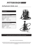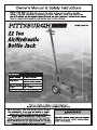
1
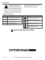
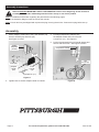
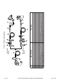
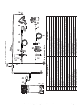
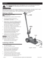
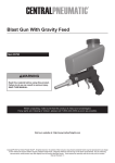
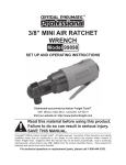
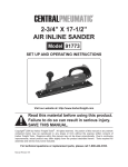
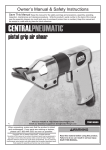
WARNING SYMBOLS AND DEFINITIONS
This is the safety alert symbol. It is used to alert you to potential personal injury hazards.
Obey all safety messages that follow this symbol to avoid possible injury or death.
Indicates a hazardous situation which, if not avoided,
will result in death or serious injury.
Indicates a hazardous situation which, if not avoided,
could result in death or serious injury.
Indicates a hazardous situation which, if not avoided,
could result in minor or moderate injury.
Addresses practices not related to personal injury.
IMPORTANT SAFETY INFORMATION
1. Study, understand, and follow all instructions
before operating this device.
14. Apply parking brake and chock
tires before lifting vehicle.
2. Do not exceed rated capacity.
15. Lift vehicle only at manufacturer
recommended locations.
3. Use only on hard, level surfaces.
4. Lifting device only. Immediately after lifting,
support the vehicle with appropriate means.
5. Do not move or dolly the vehicle while on the jack.
6. Failure to heed these markings may result in
personal injury and/or property damage.
7. Lift only areas of the vehicle as specified
by the vehicle manufacturer.
8. No alterations shall be made to this product.
9. Never work on, under or around a load
supported only by this device.
10. Do not adjust safety valve.
11. Wear ANSI-approved safety goggles and
heavy-duty work gloves during use.
12. Keep clear of load while lifting and lowering.
13. Lower load slowly.
Page 2
16. Inspect before every use; do not use
if parts are loose or damaged.
17. Do not use for aircraft purposes.
18. The warnings, precautions, and instructions
discussed in this manual cannot cover all
possible conditions and situations that may occur.
The operator must understand that common sense
and caution are factors, which cannot be built into
this product, but must be supplied by the operator.
19. The brass components of this product contain lead,
a chemical known to the State of California to cause
cancer, birth defects (or other reproductive harm).
(California Health & Safety Code § 25249.5, et seq.)
IMPORTANT! Before first use:
Check hydraulic oil level and fill to 1/4″ below
the fill port as needed as stated on page 5.
Thoroughly test the Jack for proper operation.
If it does not work properly, bleed air from its
hydraulic system as stated on page 5.
For technical questions, please call 1-800-444-3353.
Item 61476
Air Source
a.
Never connect to an air source that
is capable of exceeding 200 psi.
Over pressurizing the tool may cause
bursting, abnormal operation, breakage
of the tool or serious injury to persons.
Use only clean, dry, regulated compressed air at the
rated pressure or within the rated pressure range as
marked on the tool. Always verify prior to using the
tool that the air source has been adjusted to the rated
air pressure or within the rated air-pressure range.
b. Never use oxygen, carbon dioxide, combustible
gases or any bottled gas as an air source
for the tool. Such gases are capable of
explosion and serious injury to persons.
Symbol Definitions
Symbol
Property or statement
PSI
Pounds per square inch of pressure
CFM
Cubic Feet per Minute flow
SCFM
Cubic Feet per Minute flow
at standard conditions
NPT
National pipe thread, tapered
Chart continued in next column.
Symbol
Property or statement
WARNING marking
concerning Risk of Eye Injury.
Wear ANSI-approved eye protection.
WARNING marking concerning Risk of
Hearing Loss. Wear hearing protection.
WARNING marking concerning
Risk of Respiratory Injury. Wear
NIOSH-approved dust mask/respirator.
WARNING marking concerning
Risk of Explosion.
SAVE THESE INSTRUCTIONS.
Item 61476
For technical questions, please call 1-800-444-3353.
Page 3
Assembly Instructions
Read the ENTIRE IMPORTANT SAFETY INFORMATION section at the beginning of this document
including all text under subheadings therein before set up or use of this product.
Note: For additional information regarding the parts listed in the following pages,
refer to the Assembly Diagram near the end of this manual.
Note: This air tool may be shipped with a protective plug covering the air inlet. Remove this plug before set up.
Assembly
1. Attach Adapter Holder (66) to the Lower Handle (18)
with two U-Bolts (65) and Nuts (23).
See Figure A, below.
3. Put height adjustment Adapters into
the Adapter Holder and lock each with
a Cotter Pin (71). See Figure A.
5. Put the Handle Assembly into Handle Socket and
secure with Set Screw. See Figure B, below.
Saddle
Adapters
(67-69)
Completed Handle
U-Bolts
(65)
Set
Screw (6)
Nuts (23)
Adapter
Holder
(66)
Lower
Handle
(18)
Cotter Pin (71)
Figure A
2. Tighten Nuts to secure Adapter Holder to Handle.
Page 4
Figure B
For technical questions, please call 1-800-444-3353.
Item 61476
Air Supply
TO PREVENT SERIOUS INJURY FROM EXPLOSION:
Use only clean, dry, regulated, compressed air to power this tool. Do not use oxygen,
carbon dioxide, combustible gases, or any other bottled gas as a power source for this tool.
1. Incorporate a filter, regulator with pressure gauge,
oiler, in-line shutoff valve, and quick coupler for
best service, as shown on Figure C on page 6
and Figure D on page 7. An in-line shutoff
ball valve is an important safety device because
it controls the air supply even if the air hose
is ruptured. The shutoff valve should be a
ball valve because it can be closed quickly.
Note: If an automatic oiler system is not used,
add a few drops of Pneumatic Tool Oil to
the airline connection before operation.
Add a few more drops after each hour of continual use.
2. Attach an air hose to the compressor’s air outlet.
Connect the air hose to the Jack’s Air Inlet.
Other components, such as a connector
and quick coupler, will make operation
more efficient, but are not mandatory.
WARNING! TO PREVENT SERIOUS INJURY
FROM ACCIDENTAL OPERATION:
Do not install a female quick coupler on the tool.
Such a coupler contains an air valve that will
allow the air tool to retain pressure and operate
accidentally after the air supply is disconnected.
Note: Air flow, and therefore tool performance, can
be hindered by undersized air supply components.
The air hose must be long enough to reach
the work area with enough extra length to
allow free movement while working.
3. Turn the tool’s throttle or switch to the off position;
refer to Operation section for description of controls.
4. Close the in-line shutoff valve between
the compressor and the tool.
5. Turn on the air compressor according to
the manufacturer’s directions and allow it
to build up pressure until it cycles off.
6. Adjust the air compressor’s output regulator
so that the air output is enough to properly
power the tool, but the output will not exceed
the tool’s maximum air pressure at any time.
Adjust the pressure gradually, while checking the
air output gauge to set the right pressure range.
7. Inspect the air connections for leaks.
Repair any leaks found.
8. If the tool will not be used at this time, turn off
and detach the air supply, safely discharge any
residual air pressure, and release the throttle
and/or turn the switch to its off position
to prevent accidental operation.
Note: Residual air pressure should not be present
after the tool is disconnected from the air supply.
However, it is a good safety measure to attempt to
discharge the tool in a safe fashion after disconnecting
to ensure that the tool is disconnected and unpowered.
Bleeding Instructions
Before each use or if Bottle Jack performance decreases,
check for excessive air and proper hydraulic oil level in Bottle Jack. If Jack appears not to be working
properly, it may be necessary to purge its hydraulic system of excessive air as follows:
1. Turn Knob completely clockwise.
5. Turn Knob clockwise until snug to hold pressure.
2. Release the Air Lever Lock and depress the Air Lever
completely for a few seconds. Then turn the Knob
1-1/2 turns counterclockwise, releasing pressure.
6. Top off the reservoir with hydraulic oil.
Then replace the Filler Plug (24a).
3. Remove the Filler Plug (24a), and fill the
Reservoir (23a) with hydraulic oil (not included).
4. Depress the Air Lever completely for
a few seconds to purge air.
Item 61476
IMPORTANT: After bleeding the Bottle Jack, test the
Jack for proper operation prior to its actual use.
Note: To prevent damage to the Bottle Jack, check
for excessive air and/or low hydraulic oil regularly.
For technical questions, please call 1-800-444-3353.
Page 5
Page 6
For technical questions, please call 1-800-444-3353.
Item 61476
A
B
C
D
E
F
G
H
Air Hose
Filter
Regulator
Lubricator (optional)
Coupler and Plug
Leader Hose (optional)
Air Cleaner / Dryer (optional)
Air Adjusting Valve (optional)
Description
Non-lubricated
Tools
A
Lubricated
Tools
B
B
C
C
A
Function
A
E
E
F
H
Connects air to tool
Prevents dirt and condensation from damaging tool or workpiece
Adjusts air pressure to tool
For air tool lubrication
Provides quick connection and release
Increases coupler life
Prevents water vapor from damaging workpiece
For fine tuning airflow at tool
G
D
Figure C: Portable Air Supply Setup
Item 61476
For technical questions, please call 1-800-444-3353.
Page 7
B
A
A
B
C
D
E
F
G
H
I
J
K
L
M
N
O
Description
F
E
F
Vibration Pads
Anchor Bolts
Ball Valve
Isolation Hose
Main Air Line - 3/4″ minimum recommended
Ball Valve
Branch Air Line -1/2″ minimum recommended
Air Hose
Filter
Regulator
Lubricator (optional)
Coupler and Plug
Leader Hose (optional)
Air Cleaner / Dryer (optional)
Air Adjusting Valve (optional)
B
A
C D
G
I
I
J
K
N
J
H
Function
H
L
L
M
O
For noise and vibration reduction
Secures air compressor in place
Isolates sections of system for maintenance
For vibration reduction
Distributes air to branch lines
To drain moisture from system
Brings air to point of use
Connects air to tool
Prevents dirt and condensation from damaging tool or workpiece
Adjusts air pressure to tool
For air tool lubrication
Provides quick connection and release
Increases coupler life
Prevents water vapor from damaging workpiece
For fine tuning airflow at tool
Non-lubricated Tools
C
C
Lubricated
Tools
Slope
Figure D: Stationary Air Supply Setup
F
Operation
Read the ENTIRE IMPORTANT SAFETY INFORMATION section at the beginning of this manual
including all text under subheadings therein before set up or use of this product.
Park vehicle on a flat, level, solid, surface safely away from oncoming traffic. Turn off the vehicle’s engine.
Place the vehicle’s transmission in “PARK” (if automatic) or in its lowest gear (if manual).
Set the vehicle’s emergency brake. Then, chock the wheels that are not being lifted.
Knob
Raising a Vehicle
Note: Safety shutoff prevents lifting
in excess of rated load.
Handle
Lever
1. Pull Handle Lever to reposition handle as desired.
2. Turn Knob completely clockwise to its
locked position. Then connect an air hose
(not included) to the Air Inlet.
3. Depress the Air Lever until the Saddle of the Bottle
Jack has nearly reached the vehicle lifting point.
Position the Jack at 90° to the vehicle’s lifting point
to ensure the Bottle Jack’s Saddle and vehicle
lifting point are in alignment. If not, remove and
then reposition the Bottle Jack before lifting.
4. To lift the vehicle, continue to depress the Air Lever.
Once the vehicle is lifted, place the
Air Lever Lock in its locked position.
Saddle
Adapters
5. Set properly-rated jack stands (not included) to
the same minimum practical height according
to the manufacturer’s instructions, making
sure they lock securely into position.
6. Position the jack stand saddles under the vehicle
manufacturer’s recommended support points.
Saddle
WARNING! Ensure that the vehicle support
points are fully seated in the saddles of both
jack stands. Use a matched pair of jack stands
per vehicle to support one end only.
7. Slowly turn the Knob counterclockwise to
ease the vehicle onto the jack stands.
Air
Lever
Lock
Lowering a Vehicle
1. Remove all tools, old vehicle parts, etc.
from under the vehicle.
Air Lever
2. Turn Knob completely clockwise.
3. Release the Air Lever Lock and depress the
Air Lever to raise the vehicle slightly above
the jack stand saddles. Carefully remove
the jack stands from under the vehicle.
Figure E: Controls
Air Inlet
4. Slowly turn Knob counterclockwise
(not more than one full turn) to lower the vehicle.
5. To prevent accidents, lower the Jack completely
and disconnect its air supply after use. Clean, then
store the Jack indoors out of children’s reach.
Page 8
For technical questions, please call 1-800-444-3353.
Item 61476
Inspection, Maintenance, & Cleaning
Procedures not specifically explained in this manual
must be performed only by a qualified technician.
TO PREVENT SERIOUS INJURY FROM TOOL FAILURE:
Do not use damaged equipment. If abnormal noise or vibration occurs,
have the problem corrected before further use.
1. BEFORE EACH USE, inspect the general
condition of the tool. Check for:
3. WHEN STORING, turn Release Valve
counterclockwise to its open position. Store the Jack
and its accessories in a clean, dry, safe location out
of reach of children and other unauthorized people.
• loose hardware or housing,
• misalignment or binding of moving parts,
4. DAILY - Air Supply Maintenance:
Every day, maintain the air supply according
to the component manufacturers’ instructions.
Drain the moisture filter regularly.
Performing routine air supply maintenance
will allow the tool to operate more safely
and will also reduce wear on the tool.
• damaged air hose,
• cracked or broken parts, and
• any other condition that may
affect its safe operation.
2. AFTER USE, clean external surfaces of the Jack
with a clean, moist cloth and a mild detergent.
Do not use solvents.
5. Periodically, check the condition of the hydraulic fluid.
Change the hydraulic fluid as needed through the
Fill Plug. Thoroughly bleed jack after changing fluid.
Troubleshooting
TO PREVENT SERIOUS INJURY AND DEATH:
Use caution when troubleshooting a malfunctioning jack. Stay well clear of the supported load.
Completely resolve all problems before use. If the solutions presented in the Troubleshooting guide
do not solve the problem, have a qualified technician inspect and repair the jack before use.
After the jack is repaired: Test it carefully without a load by raising and lowering it fully,
checking for proper operation, BEFORE RETURNING THE JACK TO OPERATION.
DO NOT USE A DAMAGED OR MALFUNCTIONING JACK!
POSSIBLE SYMPTOMS
Jack will
not lift at
its weight
capacity
Saddle
lowers
under load
X
Pump
Saddle will
stroke feels not lift all
spongy
the way
Handle
Oil leaking
moves up
from filler
when jack is
plug
under load
PROBABLE SOLUTION
(Make certain that the jack is not supporting
a load while attempting a solution.)
Check that Release Valve is fully closed.
Bleed air from the system.
X
Valves may be blocked and may not close fully.
To flush the valves:
X
X
1. Lower the Saddle and securely
close the Knob.
X
2. Manually lift the Saddle several inches.
3. Open the Knob and force the Saddle
down as quickly as possible.
X
X
Jack may be low on oil.
Check the oil level and refill if needed.
X
Jack may require bleeding - see instructions.
X
Item 61476
Unit may have too much hydraulic oil inside,
check fluid level and adjust if needed.
For technical questions, please call 1-800-444-3353.
Page 9
Parts Lists and Diagrams
Main Parts List and Diagram
Part
1
2
3
4
5
6
7
8
9
10
11
12
13
14
15
16
17
18
19
20
21
22
23
24
Description
Bolt M6*10
Bolt M12*30
Right side plate
Circlip
Wheel
Bolt M10*16
Adjustable frame
Base plate
Left side plate
Handle socket
Washer ø16
Screw M4*22
Damping nut
Connector
Tie rod -1
Tie rod -2
Screw M6*10
Lower Handle
Screw M8*7
Handle connector
Slotted pin
R-Pin
Nut M8
Spring
Page 10
Qty
8
2
1
2
2
5
1
1
1
1
1
1
1
1
1
1
1
1
2
2
1
1
5
1
Part
25
26
27
28
29
30
31
32
33
34
35
36
37
38
39
40
41
42
43
44
45
46
47
48
Description
Tie rod -3
Screw M6*8
Pin
Handle Lever
Handle sleeve
Screw M6*10
Knob
Handle -2
Air Lever Lock
Air Lever
Valve cover
O-ring 18*2.4
O-ring 10.6*1.9
O-ring 3.15*1.8
O-ring 4*1.8
Throttle
Spring
Lock nut
Quick coupler-male
Valve body
Screw M4*30
Air hose
Screw M6*6
Washer
Qty
1
2
2
1
2
1
1
1
1
1
1
1
1
1
1
1
1
1
1
1
1
1
1
2
Part
49
50
51
52
53
54
55
56
57
58
59
60
61
62
63
64
65
66
67
68
69
70
71
For technical questions, please call 1-800-444-3353.
Description
Pin 4*16
Pin 4*22
Universal joint -1
Universal joint -2
Connecting pin
Rivet 3*18
Connect plate
Universal joint -3
Universal joint -4
Universal joint -5
Air motor
Washer
Pump Asm
Installation pad
Plate
Screw M5*6
U-Clamp
Adapter Holder
Saddle Adapter A
Saddle Adapter B
Saddle Adapter C
Saddle Adapter D
Cotter pin
Qty
1
1
4
3
1
2
2
2
1
1
1
1
1
2
1
4
2
1
1
1
1
1
3
Item 61476
Parts List and Diagram A - Hydraulic Unit
Part
1a
2a
3a
4a
5a
6a
7a
8a
9a
10a
11a
12a
13a
14a
15a
16a
17a
18a
19a
20a
21a
22a
23a
24a
25a
26a
27a
28a
29a
Description
Spring plate
Nylon ring
Base
Ball
Ball cup
Spring
Screw
O-ring
Screw
Plastic cap
Release valve
Spring
Top nut
O-ring
Ball
Spring
Screw
O-ring
Eye bolt
Steel block
Nut
Packing
Reservoir
Fill plug
Nylon ring
Cylinder
O-ring
Cup seal
Ram
1a
Qty
1
1
1
1
1
1
1
1
1
1
1
1
1
1
3
1
2
1
4
1
1
1
1
1
1
1
1
1
1
18a
12a
13a
2a
29a
28a
23a
24a
27a
26a
22a
19a
19a
25a
17a
10a
20a
9a
8a
7a
21a
15a
6a
19a
19a
5a
4a
3a
15a
16a
17a
11a
15a
14a
PLEASE READ THE FOLLOWING CAREFULLY
THE MANUFACTURER AND/OR DISTRIBUTOR HAS PROVIDED THE PARTS LIST AND ASSEMBLY DIAGRAM
IN THIS DOCUMENT AS A REFERENCE TOOL ONLY. NEITHER THE MANUFACTURER OR DISTRIBUTOR
MAKES ANY REPRESENTATION OR WARRANTY OF ANY KIND TO THE BUYER THAT HE OR SHE IS
QUALIFIED TO MAKE ANY REPAIRS TO THE PRODUCT, OR THAT HE OR SHE IS QUALIFIED TO REPLACE
ANY PARTS OF THE PRODUCT. IN FACT, THE MANUFACTURER AND/OR DISTRIBUTOR EXPRESSLY
STATES THAT ALL REPAIRS AND PARTS REPLACEMENTS SHOULD BE UNDERTAKEN BY CERTIFIED AND
LICENSED TECHNICIANS, AND NOT BY THE BUYER. THE BUYER ASSUMES ALL RISK AND LIABILITY
ARISING OUT OF HIS OR HER REPAIRS TO THE ORIGINAL PRODUCT OR REPLACEMENT PARTS
THERETO, OR ARISING OUT OF HIS OR HER INSTALLATION OF REPLACEMENT PARTS THERETO.
Record Serial Number Here:
Note: If product has no serial number, record month and year of purchase instead.
Note: Some parts are listed and shown for illustration purposes only, and
are not available individually as replacement parts.
Item 61476
For technical questions, please call 1-800-444-3353.
Page 11
Limited 90 Day Warranty
Harbor Freight Tools Co. makes every effort to assure that its products meet high quality and durability standards,
and warrants to the original purchaser that this product is free from defects in materials and workmanship for the
period of 90 days from the date of purchase. This warranty does not apply to damage due directly or indirectly,
to misuse, abuse, negligence or accidents, repairs or alterations outside our facilities, criminal activity, improper
installation, normal wear and tear, or to lack of maintenance. We shall in no event be liable for death, injuries
to persons or property, or for incidental, contingent, special or consequential damages arising from the use of
our product. Some states do not allow the exclusion or limitation of incidental or consequential damages, so the
above limitation of exclusion may not apply to you. THIS WARRANTY IS EXPRESSLY IN LIEU OF ALL OTHER
WARRANTIES, EXPRESS OR IMPLIED, INCLUDING THE WARRANTIES OF MERCHANTABILITY AND FITNESS.
To take advantage of this warranty, the product or part must be returned to us with transportation charges
prepaid. Proof of purchase date and an explanation of the complaint must accompany the merchandise.
If our inspection verifies the defect, we will either repair or replace the product at our election or we may
elect to refund the purchase price if we cannot readily and quickly provide you with a replacement. We will
return repaired products at our expense, but if we determine there is no defect, or that the defect resulted
from causes not within the scope of our warranty, then you must bear the cost of returning the product.
This warranty gives you specific legal rights and you may also have other rights which vary from state to state.
3491 Mission Oaks Blvd. • PO Box 6009 • Camarillo, CA 93011 • (800) 444-3353