1
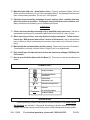
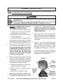
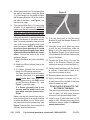
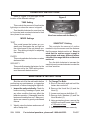
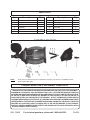
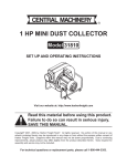
Garden Lantern
92508
INSTALLATION AND OPERATING INSTRUCTIONS
3491 Mission Oaks Blvd., Camarillo, CA 93011
Visit our Web site at http://www.harborfreight.com
TO HELP PREVENT SERIOUS INJURY AND ELECTROCUTION,
READ AND UNDERSTAND ALL WARNINGS AND
INSTRUCTIONS BEFORE INSTALLATION OR USE.
Copyright© 2005 by Harbor Freight Tools®. All rights reserved. No
portion of this manual or any artwork contained herein may be reproduced in
any shape or form without the express written consent of Harbor Freight Tools.
For technical questions and replacement parts, please call 1-800-444-3353.
PRODUCT SPECIFICATIONS
E200963
Electrical Requirements
120 VAC, 60 Hz
Light Bulb Maximum Wattage
100 (Type A ONLY)
Weight
4 lbs.
Approximate* Sensor Range
up to 19' and 180°
* External factors, such as obstructions and dirt on the sensor,
can greatly limit the sensor's effective range.
1-5 minutes
Light Timer Settings
SAVE THIS MANUAL
You will need this manual for the safety warnings and precautions, assembly,
operating, inspection, maintenance and cleaning procedures, parts list and assembly diagram. Keep your invoice with this manual. Write the invoice number on the
inside of the front cover. Keep this manual and invoice in a safe and dry place for
future reference.
GENERAL SAFETY RULES
WARNING!
READ AND UNDERSTAND ALL INSTRUCTIONS
Failure to follow all instructions listed below may result in
electric shock, fire, and/or serious injury.
SAVE THESE INSTRUCTIONS
WORK AREA
1. Keep your work area clean and well lit. Cluttered benches and dark areas invite
accidents. Make sure there is adequate surrounding workspace.
2. Do not operate lights in explosive atmospheres, such as in the presence of flammable liquids, gases, or dust. Light switches create sparks which may ignite the dust
or fumes.
3. Keep bystanders, children, and visitors away during installation. Protect others in
the work area from debris such as chips and sparks. Provide barriers or shields as
needed.
SKU 92508
For technical questions, please call 1-800-444-3353.
PAGE 2
ELECTRICAL SAFETY
4. This light must be installed into an outlet box properly installed and grounded in
accordance with all codes and ordinances. Check with a qualified electrician if
you are in doubt as to whether the outlet is properly grounded. If the light should
electrically malfunction or break down, grounding provides a low resistance path to
carry electricity away from the user.
5. During installation, avoid body contact with grounded surfaces such as pipes,
radiators, ranges, and refrigerators. There is an increased risk of electric shock if
your body is grounded.
6. Do not expose open power outlets or wires to rain or wet conditions. Work only
on a dry day with no chance of rain, and finish all work and seal the Base (1) of the
lantern BEFORE leaving the work area.
7. Do not abuse the power lines. Never use the power lines to hold the lantern
during installation. Keep the power lines away from heat, oil, sharp edges, or
moving parts. Replace damaged power lines immediately. Damaged power lines
increase the risk of electric shock.
8. Always disconnect the electrical circuit before performing any installation, internal inspection, or maintenance procedures.
9. Use the plastic hook on the Mounting Bracket (8) or other practical ways to secure and support the lantern to the outlet during installation. Holding the lantern
by hand or allowing the lantern to hang on the wires is dangerous and may damage
the wiring, leading to electric shock or fire.
PERSONAL SAFETY
10. Stay alert. Watch what you are doing, and use common sense during installation. Do not attempt to install this item while tired or under the influence of drugs,
alcohol, or medication. A moment of inattention during installation may result in serious personal injury.
11. Dress properly. Do not wear loose clothing or jewelry. Contain long hair. Keep
your hair, clothing, and gloves away from moving parts. Loose clothes, jewelry, or
long hair can be caught in moving parts during installation.
12. Do not overreach. Keep proper footing and balance at all times. Proper footing
and balance enables better control of any power tools used during installation, if an
unexpected situation arises.
13. Use safety equipment. Always wear eye protection. Dust mask, nonskid safety
shoes, hard hat, or hearing protection must be used for appropriate conditions. Always wear ANSI approved safety goggles when installing using tools and/or equipment.
14. Do not use the light if the Power Switch does not turn it on or off. Any light that
cannot be controlled with the Power Switch is dangerous and must be replaced.
SKU 92508
For technical questions, please call 1-800-444-3353.
PAGE 3
15. Maintain light with care. Keep lantern clean. Properly maintained lights will work
better and more efficiently. Do not use a damaged lantern. Tag damaged lanterns and
their corresponding switches “Do not use” until repaired.
16. Check for loose mounting, breakage of parts, and any other condition that may
affect the lantern’s operation. If damaged, have the lantern serviced before use.
Many accidents are caused by poorly maintained fixtures.
SERVICE
17. Fixture service must be performed only by qualified repair personnel. Service or
maintenance performed by unqualified personnel could result in a risk of injury.
18. When servicing a fixture, use only identical replacement parts. Follow instructions in the “Maintenance Instructions” section of this manual. Use of unauthorized
parts or failure to follow maintenance instructions may create a risk of electric shock or
injury.
19. Maintain labels and nameplates on the Lantern. These carry important information.
If unreadable or missing, contact Harbor Freight Tools for a replacement.
20. Only install type A bulbs rated at or below the maximum wattage (100 Watts) for
this Lantern.
21. Do not open the black box inside the Base (1). There are no user-serviceable parts
inside.
SYMBOLOGY
Double Insulated
Canadian Standards
Association
Underwriters
Laboratories, Inc.
V~
A
Volts Alternating Current
Amperes
no
xxxx/min.
No Load Revolutions
per Minute (RPM)
UNPACKING
When unpacking, check to make sure all the parts shown on the Parts List on
the last page are included. If any parts are missing or broken, please call Harbor
Freight Tools at the number shown on the cover of this manual as soon as possible.
SKU 92508
For technical questions, please call 1-800-444-3353.
PAGE 4
ASSEMBLY INSTRUCTIONS
NOTE: For additional information regarding the parts listed in the following pages, refer to
the Assembly Diagram on the last page.
The power to the outlet box must be disconnected before attempting to
install this item.
If the power is left connected during installation, or if the power comes on
accidentally, SEVERE PERSONAL INJURY or DEATH can occur.
installed on. Visibly label the power
1. BEFORE STARTING THE INSTALLAswitch leading to the circuit, “Work in
TION MAKE CERTAIN THAT:
progress on this circuit, DO NOT
A. All needed tools and materials are
TURN POWER ON.”
present at the work area. Weatherproof sealant is not included.
5. Remove the cover from the outlet box.
B. Sufficient time is allotted for completUse a multimeter, set to a setting approing the installation.
priate for testing 120 VAC, to determine
C. It is a dry day with no chance of rain.
that the power to the outlet is truly disconnected.
Leaving the work area without finishing
the installation creates a dangerous situ- 6. Parts 1-7 and 10 are typically preasation, and should be avoided at all costs.
sembled. Remove the Mounting Bracket
(8) if it is attached to the Base (1). Both
2. This device is installed on an electriBracket Screws (9) should remain
cal circuit that has sufficient voltage
threaded into the Bracket - see below.
to SERIOUSLY INJURE or KILL you.
If any doubt exists about your capa- 7. Using an Outlet Box Screw (12) through
bility to install this unit safely and
each slot in the Mounting Bracket (8), solproperly, this unit should be installed
idly attach it to the outlet box.
by a licensed electrician.
3. Select an appropriate switch-controlled
outlet box for installation. Having a
switch-controlled outlet allows quick disconnection in the event of an emergency.
The lantern’s mounting location:
A. Should be unblocked for optimal illumination and sensor range.
B. Must not block or interfere with any
walkways.
C. Must be out of children’s reach.
Figure 1
4. Disconnect all power connected to
the outlet box that this item is to be
SKU 92508
For technical questions, please call 1-800-444-3353.
PAGE 5
8. While being careful not to scrape either
the wall or the lantern, hang the Base
(1) of the lantern on the plastic hookon
the Mounting Bracket (10) by the hole in
the side of the Base - see Figure 1 on
the previous page.
Figure 2
9. The included Wire Nuts (11) may not be
suitable for all applications; ALWAYS
make sure that all connections are secure and, if a wire nut will not tighten
properly, supply one of appropriate size.
Using the wire nuts, carefully attach the
wires in the lantern to the power supply
lines. For each connection, twist the nuts
over both wires clockwise until both
wires are secure. NOTE: If any difference from these directions is noted
in the color/type of supply lines, have
a licensed electrician finish the installation. Secure the wires in the order
explained below:
A. Attach the Black (hot) line to the Black
wire.
B. Attach the White (neutral) line to the
white wire.
C. If a Green (ground) line is present,
attach it to the yellow-green wire.
If a Green (ground) line is not present
and the outlet box is a grounded
metal outlet box, then attach the
yellow-green wire to the GND screw
on the Mounting Bracket (8) - see
Figure 1, previous page.
If a Green (ground) line is not
present and the outlet box is not
grounded, contact a licensed electrician.
Make sure that all connections are secure and that there is no metal showing
on either the Black (hot) or White (neutral) connection before proceeding - see
Figure 2, above right, for an example of
a proper wire nut connection.
SKU 92508
10. Turn the front part of the Mounting
Bracket (8) until the Bracket Screws (9)
are horizontal.
11. Carefully, so as not to pinch any wires
or pull on any connections, slide the
Base (1) off of the plastic hook and onto
the Bracket Screws (9) so that the end
of both Bracket Screws are visible at the
front of the Base.
12. Thread the Acorn Nuts (10) onto the
ends of the Bracket Screws (9) and
tighten just enough to hold the Base (1).
13. Gently rotate the Base until the lantern
is vertical. A level can be used to ensure that the lantern is level.
14. Securely tighten the Acorn Nuts (10).
15. Apply weatherproof sealant (not included) around the top half of the base
where it meets the wall.
DO NOT APPLY SEALANT TO THE
BOTTOM OF THE BASE.
The opening at the bottom allows moisture to drain out and helps prevent
moisture from accumulating inside.
16. Install a type A light bulb rated at 100
watts or less, following the instructions
outlined in number three of the Maintenance Instructions.
For technical questions, please call 1-800-444-3353.
PAGE 6
OPERATION INSTRUCTIONS
Refer to Figure 3 on the right for the
location of the different settings.
TIME Setting
This controls the amount of time that the
light stays on when the sensor is tripped.
Turn the dial clockwise for more time (up
to 5 minutes) and counterclockwise for less
time (down to one minute).
Figure 3
View from underneath the Base (1).
MODE Settings
TEST
SENSITIVITY Setting
This mode leaves the lantern on constantly and illuminates the red light on
This controls the amount of motion
the control panel if the unit detects mo- needed to trip the sensor and the distance
tion. This setting is helpful for adjusting that the sensor detects motion at. Keep in
the sensitivity.
mind that the motion sensor’s range is
approximate and many different factors
PHOTO
This mode switches the lantern on when can affect the range that this unit detects
motion at.
darkness falls.
Turn the dial clockwise to increase the
SECURITY
sensitivity and counterclockwise to make the
This mode illuminates the lantern for the unit less sensitive.
duration set by the TIME setting whenever the sensor detects motion.
MAINTENANCE INSTRUCTIONS
Shut the unit off at the wall switch before
performing any maintenance, or inspection
procedures, or before changing the light bulb.
1. Inspect the unit periodically. Check for
loose mounting, breakage of parts, and
any other condition that may affect the
lantern’s operation. If damaged, have the
lantern serviced before use. Many accidents are caused by poorly maintained
fixtures.
2. Weekly, wipe the lantern and sensor off
with a damp cloth.
SKU 92508
3. To Change The Bulb:
A. Shut off the switch and wait until the
lantern has cooled off.
B. Remove the Hood Nut (4) and the
Hood (3).
C. Loosen and remove both Nuts (7).
D. Remove both Washers (6) and the
Hood Bracket (5).
E. Using protective gloves, remove the
old bulb and install a new type A bulb
of 100 watts or less.
F. Reassemble the lantern securely.
For technical questions, please call 1-800-444-3353.
PAGE 7
PARTS LIST
Part
Description
Q'ty
Part
Description
Q'ty
1
Base
1
7
Nut
2
2
Window
6
8
Mounting Bracket
1
3
Hood
1
9
Bracket Screw
2
4
Hood Nut
1
10
Acorn Nut
2
5
Hood Bracket
1
11
Wire Nut
3
6
Washer
2
12
Outlet Box Screw
1
ASSEMBLY DIAGRAM
NOTE:
Some parts are listed and shown for illustration purposes only, and are not available individually as replacement parts.
PLEASE READ THE FOLLOWING CAREFULLY
THE MANUFACTURER AND/OR DISTRIBUTOR HAS PROVIDED THE PARTS LIST AND ASSEMBLY
DIAGRAM IN THIS MANUAL AS A REFERENCE TOOL ONLY. NEITHER THE MANUFACTURER OR
DISTRIBUTOR MAKES ANY REPRESENTATION OR WARRANTY OF ANY KIND TO THE BUYER THAT
HE OR SHE IS QUALIFIED TO MAKE ANY REPAIRS TO THE PRODUCT, OR THAT HE OR SHE IS
QUALIFIED TO REPLACE ANY PARTS OF THE PRODUCT. IN FACT, THE MANUFACTURER AND/OR
DISTRIBUTOR EXPRESSLY STATES THAT ALL REPAIRS AND PARTS REPLACEMENTS SHOULD BE
UNDERTAKEN BY CERTIFIED AND LICENSED TECHNICIANS, AND NOT BY THE BUYER. THE BUYER
ASSUMES ALL RISK AND LIABILITY ARISING OUT OF HIS OR HER REPAIRS TO THE ORIGINAL
PRODUCT OR REPLACEMENT PARTS THERETO, OR ARISING OUT OF HIS OR HER INSTALLATION
OF REPLACEMENT PARTS THERETO.
SKU 92508
For technical questions, please call 1-800-444-3353.
PAGE 8