1
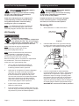
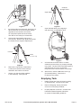
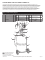
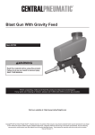
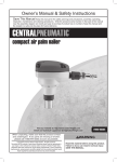
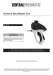
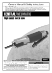
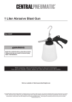
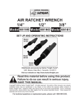
6-1/4 Gallon Oil Extractor
Item 46149
Read this material before using this product.
Failure to do so can result in serious injury.
Save this manual.
When unpacking, make sure that the product is intact and undamaged.
If any parts are missing or broken, please call 1-800-444-3353 as soon as possible.
Visit our website at: http://www.harborfreight.com
Email our tech support at: [email protected]
Copyright© 2001 by Harbor Freight Tools®. All rights reserved. No portion of this manual or any artwork contained
herein may be reproduced in any shape or form without the express written consent of Harbor Freight Tools.
Diagrams within this manual may not be drawn proportionally. Due to continuing improvements, actual product may
differ slightly from the product described herein. Tools required for assembly and service may not be included.
Manual Revised 11g
SPECIFICATIONS
Reservoir Size
Maximum Oil Level
Extraction rate
Air Inlet
Working Air Pressure
Oil Temperature
Oil Extractor Probes
(Total Qty = 5)
6-1/4 Gallons
4-1/4 Gallons
1/2 GPM Maximum
1/4 IN. - 18 NPT
70-110 PSI
68-158° F
1/4 IN. x 27-1/2 IN. L, Nylon
5/16 IN. x 27-1/2 IN. L, Nylon
5/16 IN. x 39-1/4 IN. L, Nylon
1/4 IN. x 27-1/2 IN. L, Copper
9/32 IN. x 27-1/2 IN. L, Copper
Save This Manual
Keep this manual for the safety warnings and
precautions, assembly, operating, inspection,
maintenance and cleaning procedures. Write the
product’s serial number in the back of the manual near
the assembly diagram (or month and year of purchase
if product has no number). Keep this manual and the
receipt in a safe and dry place for future reference.
Safety Alert Symbol
and Signal Words
IMPORTANT SAFETY
INFORMATION
INSTRUCTIONS PERTAINING
TO A RISK OF FIRE OR
INJURY TO PERSONS
1.
Keep children away from product usage area.
Do not allow children to handle this product.
2.
Store idle equipment. When not in use,
tools and equipment should be stored in a dry
location to inhibit rust. Always lock up tools and
equipment and keep out of reach of children.
3.
Do not use this product if under the influence
of alcohol or drugs. Read warning labels on
prescriptions to determine if your judgement or
reflexes are impaired while taking drugs. If there
is any doubt, do not attempt to use this product.
4.
Use eye protection. Wear ANSI-approved
safety goggles when using this product.
5.
Dress safely. Non-skid footwear or safety shoes
should be used when working with this product.
Do not wear loose clothing or jewelry as
they can become caught in moving parts.
Wear protective hair covering to prevent long
hair from becoming caught in moving parts.
6.
Industrial applications must
follow OSHA requirements.
7.
Do not overreach. Keep proper footing
and balance at all times to prevent
tripping, falling, and back injury, etc.
8.
Replacement parts and accessories.
When servicing, use only identical replacement
parts. Only use accessories intended for
use with this product. Approved accessories
are available from Harbor Freight Tools.
9.
Stay alert. Watch what you are doing
at all times. Use common sense.
Do not use this equipment when you are
tired or distracted from the job at hand.
10.
Check for damaged parts. Before using this
product, carefully check that it will operate properly
and perform its intended function. Check for
damaged parts and any other conditions which
may affect the operation of this product. Replace
or repair damaged or worn parts immediately.
11.
Maintain this product with care.
Keep this product clean and dry for better
and safer performance. For your safety,
service and maintenance should be performed
regularly by a qualified technician.
In this manual, on the labeling, and all other
information provided with this product:
This is the safety alert symbol. It is
used to alert you to potential personal
injury hazards. Obey all safety
messages that follow this symbol
to avoid possible injury or death.
DANGER indicates a hazardous situation which,
if not avoided, will result in death or serious injury.
WARNING indicates a hazardous situation which,
if not avoided, could result in death or serious injury.
CAUTION, used with the safety alert symbol,
indicates a hazardous situation which, if not
avoided, could result in minor or moderate injury.
NOTICE is used to address practices
not related to personal injury.
CAUTION, without the safety alert symbol, is used
to address practices not related to personal injury.
Page 2
For technical questions, please call 1-800-444-3353.
SKU 46149
12.
Use the right product for the right job. There
are certain applications for which this product was
designed. Do not use small equipment to do the
work of larger industrial equipment. Do not use this
product for a purpose for which it was not intended.
Air Source
a.
b.
Never connect to an air source that
is capable of exceeding 200 PSI.
Over pressurizing the tool may cause
bursting, abnormal operation,
breakage of the tool or serious injury
to persons. Use only clean, dry, regulated
compressed air at the rated pressure or within the
rated pressure range as marked on the tool. Always
verify prior to using the tool that the air source has
been adjusted to the rated air pressure or within the
rated air-pressure range.
Never use oxygen, carbon dioxide, combustible
gases or any bottled gas as an air source
for the tool. Such gases are capable of
explosion and serious injury to persons.
Oil Extractor Safety Warnings
1.
Maintain a safe work environment. Do not
use this product in or near damp or wet areas.
Keep work area floor free of oil, grease, and
other liquids. Do not expose this product
to rain. Keep work area well lit. Make sure
there is adequate surrounding work space.
Remove all flammable liquids and objects from
the work area. Do not operate this product in the
presence of flammable liquids, gases, or dust.
2.
Disconnect equipment from its air supply
source and release all compressed
air from the system before performing
any services or maintenance.
3.
Do not leave this product unattended
while evacuating oil.
SKU 46149
4.
Never use this equipment near open
flames, heat or ignition sources.
Allow oil to be extracted to cool down to
between 70-80° F before extracting oil.
5.
Obey the manual for the air compressor
used to power this tool.
6.
Install an in-line shutoff valve to allow
immediate control over the air supply in an
emergency, even if a hose is ruptured.
7.
Close Ball Valve (4) before pressurization.
Do not attempt to pressurize
Tank (1) with Ball Valve open.
8.
If used oil does not evacuate Tank (1)
upon pressurization, check to make
sure the Ball Valve (4) is fully closed
(with its handle in the horizontal position).
If this does not correct the problem remove
the unit from service immediately and have it
repaired by a qualified repair service technician.
9.
Disconnect air supply after evacuating oil.
10.
Do not drain caustic or flammable products.
Use as intended only.
11.
Warning! The brass components of this
product contain lead, a chemical known to
the State of California to cause birth defects
(or other reproductive harm).
(California Health & Safety code § 25249.5, et seq.)
12.
The warnings, cautions and instructions
discussed in this instruction manual cannot
cover all possible conditions and situations
that may occur. It must be understood by
the operator that common sense and caution
are factors which cannot be built into this
product, but must be supplied by the operator.
Save these
instructions.
For technical questions, please call 1-800-444-3353.
Page 3
Initial Tool Set Up/Assembly
Operating Instructions
Read the entire Important Safety
Information section at
the beginning of this manual including
all text under subheadings therein before
set up or use of this product.
Read the entire Important Safety
Information section at
the beginning of this manual including
all text under subheadings therein before
set up or use of this product.
Read and understand your air compressor’s
(sold separately) instruction manual before
using with this product. Follow all safety
warnings for your air compressor.
Inspect tool before use, looking for damaged,
loose, and missing parts. If any problems
are found, do not use tool until repaired.
Note: For additional information regarding the
parts listed in the following pages, refer to the
Assembly Diagram near the end of this manual.
Draining Oil
1.
Air Supply
Set the Extractor on a flat, level surface.
Ball Valve (4)
(Closed position)
TO PREVENT EXPLOSION:
Use only clean, dry, regulated, compressed
air to operate this tool. Do not use oxygen,
carbon dioxide, combustible gases, or any
other bottled gas as a power source for this tool.
Figure A
2.
Note: The Extractor may be shipped with
a protective plug covering the air inlet.
Remove this plug before set up.
Close the Ball Valve Lever (4) on the Hose (5)
by turning its handle perpendicular to the Hose.
See Figure A. Hand tighten Emptying Cap (9).
Note: Air flow, and therefore tool performance,
can be hindered by undersized air supply
components. The compressor air hose must
be long enough to reach the work area.
Air Inlet
1/4" NPT
Before connecting the air compressor to depressurize
the Oil Extractor, run the air compressor to
make sure it is in good working order.
1.
Turn on the air compressor according to
the manufacturer’s directions and allow it
to build up pressure until it cycles off.
2.
Adjust the Air Compressor’s Pressure Regulator
so that the air output is enough to properly
power the tool, but the output will not exceed
the tool’s maximum air pressure at any time.
Turn the knob clockwise to increase the pressure
and counter-clockwise to decrease pressure.
Adjust the pressure gradually, while checking
the air output gauge to set the pressure.
3.
Inspect the air connections for leaks.
Repair any leaks found.
4.
If the compressor will not be used at this time, turn
off the air supply and safely discharge any residual
air pressure to prevent accidental operation.
Page 4
Emptying
Cap (9)
Figure B
3.
Connect compressed air (sold separately)
(recommended 90 PSI) to coupler. See Figure B.
Adjust the air compressor’s output regulator so
that the air output is enough to properly power
the Extractor, but the output will not exceed the
Extractor’s maximum air pressure at any time.
Adjust the pressure gradually, while checking the
air output gauge to set the right pressure range.
WARNING! Do not exceed 110 PSI air pressure.
For technical questions, please call 1-800-444-3353.
SKU 46149
Oil flows
through Probe
Open Valve
Muffler
8.
Figure C
4.
Air will be pulled out of the tank. See Figure C.
When the arrow on the Air Pressure Gauge
approaches the red field, shut off the
air compressor (about 60-80 seconds).
The Tank is now ready for oil extraction.
5.
Choose the appropriate Probe (one of
five choices). Remove the dipstick and insert
the Probe into the engine’s diptsick port.
Figure E
Open the Ball Valve (4) by aligning it
with the Hose; oil will begin to flow.
Emptying
Cap (9)
Oil Level
Tube (8)
Hose (5)
Probe
(7, 10, 11, 12 or 13)
Figure F
Cap
9.
Oil should be removed when it is 70-80°,
otherwise personal injury or property damage
may result. The Oil Level Tube (See Figure F)
will show how much oil is in the tank.
Keep the Probe near the bottom of the sump.
10.
When done, close the Ball Valve Lever (4)
(horizontal position). Remove the
Probe from the vehicle.
Figure D
6.
Remove the cap (which is attached to
a chain) from the end of the Hose (5)
and attach the Probe to the Hose.
7.
Secure over the two rubber gaskets
in the Assembly. See Figure D.
Emptying Tank
SKU 46149
1.
Detach Probe and close off Hose by putting
on attached Cap. Disconnect Air Hose.
2.
Remove Emptying Cap (9) and drain
oil into an oil recycling container.
3.
Properly dispose of used oil. Contact local
Hazardous Waste Disposal Authorities
for proper oil disposable guidelines.
For technical questions, please call 1-800-444-3353.
Page 5
User‑Maintenance Instructions
Procedures not specifically explained in this manual must
be performed only by a qualified technician.
To prevent serious injury from TOOL FAILURE:
Do not use damaged equipment. If abnormal noise or vibration,
occurs, have the problem corrected before further use.
Note: These procedures are in addition to the regular checks and maintenance
explained as part of the regular operation of the air-operated tool.
1.
Before each use, inspect the general condition of the Oil Extractor. Check for broken or bent parts, loose or
missing parts, and any condition that may affect the proper operation of the product.
If a problem occurs, have the problem corrected before further use. Do not use damaged equipment.
2.
After each use, clean and dry the unit.
Record Product’s Serial Number Here:
Note: If product has no serial number, record month and year of purchase instead.
Page 6
For technical questions, please call 1-800-444-3353.
SKU 46149
PLEASE READ THE FOLLOWING CAREFULLY
THE MANUFACTURER AND/OR DISTRIBUTOR HAS PROVIDED THE PARTS DIAGRAM IN THIS MANUAL AS A
REFERENCE TOOL ONLY. NEITHER THE MANUFACTURER NOR DISTRIBUTOR MAKES ANY REPRESENTATION OR
WARRANTY OF ANY KIND TO THE BUYER THAT HE OR SHE IS QUALIFIED TO MAKE ANY REPAIRS TO THE PRODUCT
OR THAT HE OR SHE IS QUALIFIED TO REPLACE ANY PARTS OF THE PRODUCT. IN FACT, THE MANUFACTURER
AND/OR DISTRIBUTOR EXPRESSLY STATES THAT ALL REPAIRS AND PARTS REPLACEMENTS SHOULD BE
UNDERTAKEN BY CERTIFIED AND LICENSED TECHNICIANS AND NOT BY THE BUYER. THE BUYER ASSUMES
ALL RISK AND LIABILITY ARISING OUT OF HIS OR HER REPAIRS TO THE ORIGINAL PRODUCT OR REPLACEMENT
PARTS THERETO, OR ARISING OUT OF HIS OR HER INSTALLATION OF REPLACEMENT PARTS THERETO.
Parts List And Assembly Diagram
Part
1
2
3
4
5
6
Description
Tank
Air Pressure Gauge
Air Inlet
Ball Valve with Lever
Hose/Nozzle
(6' 2-1/2" L)
Wheels
Qty Part
1
1
1
1
8
9
1
10
2
7
4
Description
Nylon Probe
(5/16" D x 39-1/4" L)
Oil Level Tube
Emptying Cap
Copper Probe
(1/4" D X 27-1/2" L)
13
12 11
Qty Part
1
11
1
1
12
1
13
14
Description
Nylon Probe
(1/4" D x 27-1/2" L)
Nylon Probe
(5/16" D x 27-1/2" L)
Copper Probe
(9/32" D
x 27-1/2" L)
Probes
Muffler
Qty
1
1
1
1
10
7
2
14
3
9
1
5
8
6
Note: Some parts are listed and
shown for illustration purposes
only and are not available
individually as replacement parts.
SKU 46149
For technical questions, please call 1-800-444-3353.
Page 7
Limited 90 Day Warranty
Harbor Freight Tools Co. makes every effort to assure that its products meet high quality and durability standards,
and warrants to the original purchaser that this product is free from defects in materials and workmanship for the
period of 90 days from the date of purchase. This warranty does not apply to damage due directly or indirectly,
to misuse, abuse, negligence or accidents, repairs or alterations outside our facilities, criminal activity, improper
installation, normal wear and tear, or to lack of maintenance. We shall in no event be liable for death, injuries
to persons or property, or for incidental, contingent, special or consequential damages arising from the use of
our product. Some states do not allow the exclusion or limitation of incidental or consequential damages, so the
above limitation of exclusion may not apply to you. This warranty is expressly in lieu of all other
warranties, express or implied, including the warranties of merchantability and fitness.
To take advantage of this warranty, the product or part must be returned to us with transportation charges
prepaid. Proof of purchase date and an explanation of the complaint must accompany the merchandise.
If our inspection verifies the defect, we will either repair or replace the product at our election or we may
elect to refund the purchase price if we cannot readily and quickly provide you with a replacement. We will
return repaired products at our expense, but if we determine there is no defect, or that the defect resulted
from causes not within the scope of our warranty, then you must bear the cost of returning the product.
This warranty gives you specific legal rights and you may also have other rights which vary from state to state.
3491 Mission Oaks Blvd. • PO Box 6009 • Camarillo, CA 93011 • (800) 444-3353