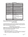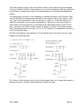
1
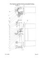
8” x 12” lathe
44859
Assembly and operating instructions
Distributed exclusively by Harbor Freight Tools®.
3491 Mission Oaks Blvd., Camarillo, CA 93011
Visit our website at: http://www.harborfreight.com
Read this material before using this product.
Failure to do so can result in serious injury.
Save this manual.
Copyright© 2001 by Harbor Freight Tools®. All rights reserved. No portion of this manual or any artwork
contained herein may be reproduced in any shape or form without the express written consent of Harbor Freight
Tools. Diagrams within this manual may not be drawn proportionally. Due to continuing improvements, actual
product may differ slightly from the product described herein. Tools required for assembly and service may not
be included.
For technical questions or replacement parts, please call 1-800-444-3353.
Revised 09g
Specifications
ITEM
DESCRIPTION
Power
110VAC, 60 Hz, 550 watts
Motor
3/4 HP
Distance between Centers
12 inches
Swing over Bed
8 inches
Spindle Step Speeds
125, 210, 420, 620, 1000, 2000 RPM
Spindle Bore
3/4 inch
Spindle Taper
MT3
Tailstock Taper
MT2
Chuck Capacity
4 inch, 3-jaw; reversing jaws
Cross Slide Travel
4-1/2 inches
Tool Slide Travel
2-3/4 inches
Slide Scale
0.001 inch per mark tool
Metric Thread Pitches
10 (0.4 ~ 3.0 mm)
SAE Thread Pitches
12 (8 ~ 40 TPI)
Accessories
- 3 reverse jaws for chuck
- Chuck wrench
- Dead centers MT2 and MT3
- Wrenches: 10-12 open end, 14-17 open end
17-19 open end, 45-52 round nut, tool post
- Hex wrenches: 3, 4, 5, 6mm
- 2 Drive Belts
- Threading gear set
Weight
254 lb.
NOTE: The Splash Guard shown in the cover page photo is not included. It can be
ordered from Harbor Freight Tools using SKU 26962.
Save This Manual
You will need the manual for the safety warnings and precautions, assembly instructions,
operating and maintenance procedures, parts list and diagram. Keep your invoice with this
manual. Write the invoice number on the inside of the front cover. Keep the manual and
invoice in a safe and dry place for future reference.
Safety Warnings and Precautions
WARNING: When using tool, basic safety precautions should always be followed to
reduce the risk of personal injury and damage to equipment.
Read all instructions before using this tool!
1.
Keep work area clean. Cluttered areas invite injuries.
2.
Observe work area conditions. Do not use machines or power tools in damp or wet
locations. Don’t expose to rain. Keep work area well lighted. Do not use electrically
powered tools in the presence of flammable gases or liquids.
07h, 07l
SKU 44859
Page 2
3.
Keep children away. Children must never be allowed in the work area. Do not let
them handle machines, tools, or extension cords.
4.
Store idle equipment. When not in use, tools must be stored in a dry location to
inhibit rust. Always lock up tools and keep out of reach of children.
5.
Do not force tool. It will do the job better and more safely at the rate for which it was
intended. Do not use inappropriate attachments in an attempt to exceed the tool
capacity.
6.
Use the right tool for the job. Do not attempt to force a small tool or attachment to
do the work of a larger industrial tool. There are certain applications for which this tool
was designed. Do not modify this tool and do not use this tool for a purpose for which
it was not intended.
7.
Dress properly. Do not wear loose clothing or jewelry as they can be caught in
moving parts. Protective, electrically non-conductive clothes and non-skid footwear
are recommended when working. Wear restrictive hair covering to contain long hair.
8.
Use eye and ear protection. Always wear ANSI approved impact safety goggles.
Wear a full face shield if you are producing metal filings or wood chips. Wear an ANSI
approved dust mask or respirator when working around metal, wood, and chemical
dusts and mists.
9.
Do not overreach. Keep proper footing and balance at all times. Do not reach over or
across running machines.
10. Maintain tools with care. Keep tools sharp and clean for better and safer
performance. Follow instructions for lubricating and changing accessories. Inspect tool
cords periodically and, if damaged, have them repaired by an authorized technician.
The handles must be kept clean, dry, and free from oil and grease at all times.
11. Disconnect power. Unplug tool when not in use.
12. Remove adjusting keys and wrenches. Check that keys and adjusting wrenches
are removed from the tool or machine work surface before plugging it in.
13. Avoid unintentional starting. Be sure the switch is in the Off position when not in
use and before plugging in.
14. Stay alert. Watch what you are doing, use common sense. Do not operate any tool
when you are tired.
15. Check for damaged parts. Before using any tool, any part that appears damaged
should be carefully checked to determine that it will operate properly and perform its
intended function. Check for alignment and binding of moving parts; any broken parts
or mounting fixtures; and any other condition that may affect proper operation. Any
part that is damaged should be properly repaired or replaced by a qualified technician.
Do not use the tool if any switch does not turn On and Off properly.
16. Guard against electric shock. Prevent body contact with grounded surfaces such as
pipes, radiators, ranges, and refrigerator enclosures.
17. Replacement parts and accessories. When servicing, use only identical
SKU 44859
Page 3
replacement parts. Use of any other parts will void the warranty. Only use accessories
intended for use with this tool. Approved accessories are available from Harbor Freight
Tools.
18. Do not operate tool if under the influence of alcohol or drugs. Read warning
labels on prescriptions to determine if your judgment or reflexes are impaired while
taking drugs. If there is any doubt, do not operate the tool.
19. Use proper size and type extension cord. If an extension cord is required, it must be
of the proper size and type to supply the correct current to the tool without heating up.
Otherwise, the extension cord could melt and catch fire, or cause electrical damage
to the tool. This tool requires use of an extension cord of 0 to 12 amps capability (up
to 50 feet), with wire size rated at 16 AWG. Longer extension cords require larger size
wire. If you are using the tool outdoors, use an extension cord rated for outdoor use
(signified by “WA” on the jacket).
21. Maintenance. For your safety, service and maintenance should be performed
regularly by a qualified technician.
22. Know your power tool. Read and understand this assembly and operating manual,
and labels affixed to the tool. Learn it’s application and limitations, as well as the
specific potential hazards particular to this tool.
23. Ground the tool. This tool is equipped with an approved 3-conductor cord and 3prong grounding type plug to fit a grounding type receptacle. The green wire in the
cord is the grounding wire. Never connect the green wire to a live terminal.
24. Use safety guards. Keep guards in place, in working order, and in proper adjustment
and alignment.
25. Secure workpiece. Use clamps or a vise to hold workpiece when practical. Keep both
hands free to operate tool.
26. Direction of Feed. Feed workpiece into the blade or cutter against the direction of the
rotation.
Note: Performance of this tool may vary depending on variations in local line voltage. Extension cord usage may also affect tool performance.
Warning: The warnings, cautions, and instructions discussed in this instruction manual
cannot cover all possible conditions and situations that may occur. It must be understood by the operator that common sense and caution are factors which cannot be built
into this product, but must be supplied by the operator.
Unpacking
When unpacking, check to make sure that all the parts are included. Refer to the Accessories list in the Specifications table, and the Parts List.
If any parts are missing or broken, please call Harbor Freight Tools at the number on the
cover of this manual as soon as possible.
SKU 44859
07h
Page 4
Installation
1.
Carefully place the Lathe on a sturdy, level work table with sufficient light.
2.
Use appropriate hardware (not included) in the mounting holes of the lathe base, to
properly secure the lathe. The work table must also be properly mounted to the floor.
3.
Before operation, verify that the slide, worktable, and spindle can move, and are not
locked in place.
4.
Clean machine with nonflammable solvent and oil the machine according to the
lubrication requirements (see Lubrication section) before running the machine.
Operation
This 8 x 12 inch Lathe is capable of machining metal and nonmetallic stock by cutting,
drilling, and milling. It can cut circular surfaces, both inside and out, cones, mill planes or
grooves, and other cutting functions depending on the tools used. It can also create SAE
B
and metric threads.
A
Controls
E
F
H
I
D
C
G
NOTE: The Splash Guard shown in the photo above is not included. It can be ordered using SKU 26962.
ITEM
NAME
USAGE
ASSY NO.
A
Reversing Switch Change rotation direction of the spindle
200
B
Master Switch
Turn machine power On and Off
200
C
Turn Lever
Moves saddle transversely
500
D
Turn Lever
Moves saddle longitudinally
600
E
Straight Lever
Clamps the square tool rest
400
F
Straight Lever
Moves the square tool rest carriage longitudinally
400
G
Straight Lever
Controls apron clasp nut
600
H
Straight Lever
Controls tailstock sleeve
300
I
Turn Lever
Moves tailstock sleeve longitudinally
300
SKU 44859
07h
Page 5
Lathe Safety Precautions
1.
Keep fingers away from revolving parts and cutting tools while in operation.
2.
Never force cutting action.
3.
Never perform an abnormal or little used operation without study and use of adequate
blocks, jigs, stops, and fixtures.
4.
Verify proper cutting speed for the material being cut, and any special operation, in a
machinery shop handbook.
5.
Do not open drive cover while in operation.
6.
Always remove chuck key from chuck.
7.
Do not attempt to adjust or remove tools when lathe is in operation.
8.
Always keep cutting tools sharp.
Cutting Procedures
The instructions that follow are basic operational procedures. It is assumed that the operator understands lathe operation and it’s capabilities.
1.
Rotate Turn Lever (C) counterclockwise to move the saddle outward.
2.
Place the workpiece in the chuck, center, and secure with the chuck key.
3.
Loosen the Straight Lever (H) and then rotate the Turn Lever (I) clockwise to engage
the Dead Center tool into the end of the workpiece. Tighten Straight Lever (H) again.
4.
Select the desired tool set and place it into the tool rest. Align the tool nose to the
spindle centerline, then tighten.
5.
Open the Gear Box and verify that the proper
speed is engaged.
Typically, the harder the metal workpiece, the
faster the spindle speed.
6.
Set the desired feed amount according to the
type of stock, workpiece dimensions, and the
type of cut.
7.
Close the Gear Box.
8.
Open the safety cover over the On / Off switch and press the green On button.
Verify that the lathe head and feed amount is correct.
9.
Align the tool nose on the workpiece where the cut is to begin.
10. Rotate the Turn Lever (C) clockwise to move the saddle transversely, moving the tool
nose into the workpiece for cutting.
11. When the cut is complete, press the red Off button.
SKU 44859
Page 6
Machining Cylinders
1.
Repeat the cutting procedure steps 1 through 8, listed on the previous page.
2.
Rotate Turn Lever (D) clockwise and move the saddle to the right of the workpiece.
3.
Rotate Turn Lever (C) clockwise until the desired depth of cut is reached on the far
right surface of the work piece.
4.
Press down on the Straight Lever (G) to engage apron clasp nut over the Gear Shaft.
The tool will automatically move from right to left while cutting the workpiece.
5.
When the cut is complete, press the red Off button.
Optionally, you can turn the Reverse switch to have the tool go over the same cut in
the opposite direction (left-to-right). This will clean and smooth the previous cut.
6.
When the cut is complete, press the red Off button.
Machining Cones
Manually
This operation is similar to machining cylinders with the following differences.
1.
To manually cut a cone, determine the taper requirement and turn the small cutter rest
to the desired slope on the workpiece. Retighten the cutter rest.
2.
Press the green On button to start the lathe.
3.
Turn the Straight Lever (F) clockwise to make the cut.
Automatically
1.
To automatically cut a cone, determine the taper requirement and turn the small cutter
rest to the desired slope on the workpiece. Retighten the cutter rest.
2.
Horizontally move the tailstock from the spindle centerline to the required slope on the
far right surface of the work piece.
3.
Press the green On button to start the lathe.
4.
Press down on the Straight Lever (G) to engage apron clasp nut over the Gear Shaft.
The tool will automatically move from right to left while cutting the workpiece.
5.
Repeat steps 2 through 4 until the desired cone size is cut.
6.
When the cut is complete, press the red Off button.
Machining Threads
The Gear Box is composed of the change gears, shaft bolt, fixing shaft bolt, and square
nut. The change gear box is fixed on the left support of the leadscrew (101). To cut threads,
select the proper change gears for the desired thread type (see Thread Formula Table), and
engage with approximately 0.1 mm tolerance. Tighten Screw (835).
SKU 44859
Page 7
The Fixed Shaft Bolt (825) under the spindle is used for right hand cutting and threading.
The set of Fixed Shaft Bolts in the accessory kit is used in combination with the original set
of Shaft Bolts to reverse the rotation of the long leadscrew for left-handed threading and
cutting.
The change gear for metric or inch threading is selected according to the Thread to Gear
formula and table. The feed amount depends on the material to be cut, the surface roughness, and finish requirements. If the two settings “0.1 and 0.2”, of the Gear table do not
meet the requirement, you can add or change gears. The same is true if the number of
teeth listed in the Gear table do not coincide with the calculated number of teeth. In this
case, use gears with similar number of teeth. In doing so, however, the following relationship of the driving shaft must be met: Z3+Z4+>Z2+Z5. Otherwise, the addendum of circles A2
and Z5 will hit each other.
The left formula below is an example of 0.3 mm spindle round. The right formula is an example for 8 threads per inch.
The Thread to Gear settings table on the following page allows you to select the number of
threads per inch or millimeter, and which gears need to be used.
SKU 44859
Page 8
Rest Accessories
The Follow Rest (not supplied) is mainly used for cutting long and thin shaft pieces to ensure no bending takes place during cutting. It also provides a better finish surface as a
result of less vibration. The Steady Rest (not supplied) provides a similar function as with
the Follow Rest. The difference being that the Steady Rest is fixed on the bed guides, and
does not follow the movement of the cutting tool. Both rests can be purchased from Harbor
Freight Tools.
Maintenance
General
1.
Unplug power cord from receptacle when not in use.
2.
Using compressed air, blow off all dirt and particles after using.
3.
Keep all tools sharp.
4.
Cover Lathe when not in use.
5.
Periodically, check all bolts and nuts for tightness.
Lubrication
Lubricate the Lathe daily using an appropriate machine oil from a forced-feed oil can.
SKU 44859
Page 9
ITEM
PART TO BE LUBRICATED
LUBE POINT
See lubrication location illustration on next page
1
Fix bolt of intermediate gear
Oil Cup
2
Leadscrew support
Oil Cup
3
Cutter rest screw
Oil Cup
4
Cutter rest carriage
Oil Cup
5
Tailstock sleeve
Oil Cup
6
Tailstock leadscrew
Oil Cup
7
Leadscrew support
Oil Cup
8
Sync. counter-pulley over shaft
Oil Cup
9
Change gear, shaft bolt
Oil Cup
10
Change gear
Oil Cup
11
Bed guides
Oil Cup
12
Saddle Carriage
Oil Cup
13
Saddle leadscrew
Oil Cup
14
Saddle Carriage
Oil Cup
15
Bed guides
Oil Cup
16
Cutter rest leadscrew
Oil Cup
17
Apron
Oil Cup
18
Bed guides
Oil Cup
19
Saddle carriage leadscrew support
Oil Cup
20
Apron
Oil Cup
21
Bed guides
Oil Cup
22
Leadscrew
On Leadscrew
Lubrication Points
SKU 44859
Page 10
SKU 44859
Page 11
Headstock Parts List
ITEM #
NAME
QTY
201
Front Oil Ring
1
202
Roller Bearing
2
203
Oil Ring
1
204
Screw
4
205
Front Panel
1
206
Rear Oil Ring
1
207
Tube Separator
1
208
Spindle Pulley
1
209
Nut
2
210
Spindle Gear
1
REMARKS
35x62x17
M3x8
M27x1.5
211
Screw
4
212
Switch Box
1
M5x10
213
Headstock
1
214
Plat Key
1
4x40
215
Screw
3
M8x16
216
Spindle
1
217
Cover
1
NOTE: Some parts are listed and shown for illustration purposes only and are not available
individually as replacement parts.
PLEASE READ THE FOLLOWING CAREFULLY
THE MANUFACTURER AND/OR DISTRIBUTOR HAS PROVIDED THE PARTS DIAGRAM IN THIS
MANUAL AS A REFERENCE TOOL ONLY. NEITHER THE MANUFACTURER NOR DISTRIBUTOR MAKES ANY REPRESENTATION OR WARRANTY OF ANY KIND TO THE BUYER THAT
HE OR SHE IS QUALIFIED TO MAKE ANY REPAIRS TO THE PRODUCT OR THAT HE OR SHE
IS QUALIFIED TO REPLACE ANY PARTS OF THE PRODUCT. IN FACT, THE MANUFACTURER
AND/OR DISTRIBUTOR EXPRESSLY STATES THAT ALL REPAIRS AND PARTS REPLACEMENTS
SHOULD BE UNDERTAKEN BY CERTIFIED AND LICENSED TECHNICIANS AND NOT BY THE
BUYER. THE BUYER ASSUMES ALL RISK AND LIABILITY ARISING OUT OF HIS OR HER
REPAIRS TO THE ORIGINAL PRODUCT OR REPLACEMENT PARTS THERETO, OR ARISING
OUT OF HIS OR HER INSTALLATION OF REPLACEMENT PARTS THERETO.
SKU 44859
Page 12
Headstock Assembly Drawing
SKU 44859
Motor and Pulley Drive Parts List
Page 13
Motor and Pulley Drive Parts List
ITEM #
NAME
QTY
REMARKS
1537
Check Ring
1
M5
1538
Motor Pulley
1
1539
Screw
5
1540
Check Ring
1
1541
Synchronized Drive
Pulley
1
1501
Nut
3
1502
Synchronized Counter
Pulley
1
1503
Slide Bearing
1
1504
Shaft
1
1505
Over Plate
1
1542
Hinge
2
Check Ring
1
M5x8
75(3”)
1506
Washer
1
12
1543
1507
Washer
1
10
1544
Motor
1
550W
1508
Nut
1
M12
1545
Washer
4
8
1509
Nut
1
M10
1546
Bolt
4
M8x25
1510
Nut
1
M12
1511
Screw
4
M5x8
1512
Motor Guard Assembly
1
1513
Bolt
3
1514
Washer
1
1515
Washer
1
1516
Fan-Support
1
1517
Protecting Cover Rest
1
1518
Washer
1
8
1519
Screw
2
M5x12
1520
Synchronized Tooth
Belt
1
M1.5xZ118
1521
V-Belt
1
0-710
1522
Pivot
1
1523
Bolt
1
1524
Bearing Arbor
1
1525
Tension Pulley
1
1526
Single Row Annular
Bearing
2
12x28x8
1527
Check Ring
1
12
1528
Tube Separator
1
1529
Front Feed Oil Cup
1
6
1530
Check Ring
1
12
1531
Big Washer
1
1532
Check Ring
1
12
1533
Check Ring
1
28
1534
Front Panel
1
1535
Cover
1
1536
Screw
1
M10x20
M8x20
M5x35
REV 09g
SKU 44859
Page 14
Motor and Pulley Drive Assembly Drawing
SKU 44859
Page 15
Bed Parts List
ITEM #
SKU 44859
NAME
QTY
REMARKS
101
Left Support of Lead Screw
1
102
Flat Key
1
4x6
107
Bed
1
A 400B 555
108
Screw
1
M8 x 12
109
Screw
A4B5
M5 x 16
110
Oil Cup
2
111
Right Support of Lead Screw
1
112
Screw
1
M6 x 16
113
Laer-pin
1
6 x 22
114
Lead Screw
1
115
Rack
1
116
Screw
3
117
Adjusting Disc
1
118
Spring Pin
2
M4 x 16
5 x 16
Page 16
Bed Assembly Drawing
SKU 44859
Page 17
Tailstock Parts List
ITEM #
NAME
QTY
REMARKS
M8x20
301
Screw
1
303
Washer
1
B12
304
Nut
1
M12
305
Tailstock Body
1
306
Single Row Radial Ball Bearing
1
307
Tailstock Leadscrew
1
308
Tailstock Sleeve
1
310
Washer
1
311
Bolt
1
312
Hand Lever
1
313
Force Feed Oil Cup
2
314
T-type Flat Key
1
315
Screw
1
M8x16
316
Screw
4
M5x16
317
Tailstock End Cover
1
318
Cylinder Pin
1
319
Spring Bow
1
320
Handwheel
1
321
Hand Lever Bolt
1
322
Hand Lever Sleeve
1
323
Index Ring
1
324
Bolt
1
325
Tailstock Clamp Plate
1
326
Base
1
SKU 44859
8101
B8
6
4x30
M12x80
Page 18
Tailstock Assembly Drawing
SKU 44859
Page 19
Rest Parts List
ITEM #
SKU 44859
NAME
QTY
REMARKS
401
Nut
2
402
Index Piece
1
403
Rivet
2
404
Cutter Rest Revolving Disc
1
405
Rest Bolt
1
406
Nut
3
M4
407
Screw
3
M4x20
408
Screw
1
M4x12
409
Nut
1
M4
410
Position Pin
1
411
Square Cutter Rest
1
412
Screw
8
413
Hand Lever
1
414
Hand Lever Base
1
415
Washer
1
416
Spring
1
417
Cutter Rest Carriage
1
418
Pad Iron
1
419
Cylinder Pin
1
420
Cutter Rest Carriage Lead
1
421
Flat Key
1
3x10
422
Force Feed Oil Cup
2
6
423
Leadscrew Support
1
424
Screw
2
425
Spring Bow
1
426
Hand Lever
2
427
Nut
1
M8
428
Washer
1
B8
429
Cutter Rest Carriage Hand Wheel
1
430
Index Ring
1
431
Screw
2
432
Clamp Disc
1
M8x25
3x10
M5x16
M6x22
Page 20
Rest Assembly Drawing
SKU 44859
Page 21
Saddle Parts List
ITEM #
SKU 44859
NAME
QTY
REMARKS
M5x10
501
Screw
1
502
Washer
1
503
Oil Cup
9
504
Nut
1
505
Middle Saddle
1
506
Large Saddle
1
507
Screw
4
M5x20
508
Screw
1
M8x20
509
Screw
4
M6x35
510
Protecting panel and oil-stopping falt
1
511
Screw
2
512
Protecting panel and oil-stopping falt
1
513
Screw
4
M525
514
Nut
4
M5
515
Pad Iron
1
516
Protecting panel and oil-stopping falt
1
517
Screw
8
518
Rear-clamp plate
1
519
Pad Iron
1
520
Screw
4
M5x16
521
Nut
5
M4x16
522
Screw
5
M4x16
523
Protecting panel and oil-stopping falt
1
524
Flat Key
1
4x8
525
Screw
3
M5x22
526
Pring Bow
1
527
Washer
1
528
Screw
1
529
Bracking Plate
1
530
Saddle Front-clamp Plate
1
531
Hand Lever Bolt
1
532
Hand Lever Sleeve
1
533
Hand wheel
1
534
Rolling Bearing
1
8101
535
Index Ring
1
100 Rulled
536
Bearing Base
1
0.02mm
537
Rolling Bearing
1
8101
538
Leadscrew
1
10TPI
539
Leadscrew support
1
540
Nut
1
10TPI
541
Screw
2
M3x16
542
Screw
2
M8x20
M8x10
M3x12
M6x10
Page 22
Saddle Assembly Drawing
SKU 44859
Page 23
Apron Parts List
ITEM #
SKU 44859
NAME
QTY
REMARKS
601
Slotted Disc
1
602
Taper Pin
1
603
Shaft Sleeve
1
604
Case
1
605
Bolt
3
M5x30
606
Nut
3
M5
607
Revolving Shaft
1
608
Hand Lever
1
Shared Piece
609
Steel Ball
1
5
610
Spring
1
08x5x25
611
Positioning Lever
1
612
Screw
1
M6x10
613
Screw
1
M6x20
614
Screw
3
M4x8
615
Flanged Shaft Sleeve
1
616
Taper Pin
1
617
Hand Lever Sleeve
1
618
Hand Lever Sleeve
1
619
Handwheel
1
Shared Piece
620
Screw
3
M4x8
621
Small Flanged Shaft Sleeve
1
622
Small Gear Shaft
1
623
Shaft Sleeve
1
624
Gear
1
625
Shaft Sleeve
1
626
Flat Key
1
627
Gear Shaft
1
628
Screw
2
M4x8
629
Nut
1
M5x30
630
Screw
1
M5x25
631
Clasp-nut
1 set
632
Pad Iron
1
633
Cylinderial Pin
2
3x20
3x30
5x10
5x12
Page 24
Apron Assembly Drawing
SKU 44859
Page 25
Gear Box Parts List
ITEM #
SKU 44859
NAME
QTY
REMARKS
801
Change Gear
2
Z70
802
Change Gear
1
Z68
803
Change Gear
1
Z66
804
Change Gear
1
Z60
805
Change Gear
1
Z50
806
Change Gear
1
Z48
807
Change Gear
1
Z45
808
Change Gear
1
Z40
809
Change Gear
1
Z100
810
Washer
1
811
Check Ring
1
6
812
Screw
1
M5x8
813
Change Gear
1
Z30
814
Change Gear
1
Z90
815
Shaft Bolt
2
816
Nut
2
M12
817
Oil Cup
3
6
818
Change Gear
1
Z80
819
Change Gear
1
Z35
820
Open Washer
2
821
Rolling Bearing
1
12x28x8
822
Intermediate Gear
1
Z40
823
Check Ring
1
Z12
824
Outer Washer
1
825
Fixed Shaft Bolt
1
826
Washer
1
10
827
Screw
2
M5x8
828
Washer
1
6
829
Screw
1
M6x10
830
Cover
1
831
Slide Bearing
2
832
Washer
3
833
Change Gear Box
1
834
Square Nut
2
835
Screw
1
M6x35
836
Change Gear
1
Z75
837
Chang Gear
1
Z72
Page 26
Gear Box Assembly Drawing
Drive System Parts List
SKU 44859
Page 27
Drive System Parts List
ITEM #
NAME
No.of Modular Thread Dia.of Pulley
Teeth
Pitch
Hand
Component
No.
REMARKS
1
Synchronized Drive Pulley
19
1.5
2
Change Gear
25
1
3
Spindle Pulley
4
Spindle Gear
6
Lead Screw
12TPI
Right
01
8
Clearance Elimination Nut
10TPI
Left
05
9
Carriage Leadscrew
10TPI
Left
05
10
Cutter Rest Leadscrew
20TPI
Right
04
11
Cutter Rest Revolving Disc
20TPI
Right
04
12
Gear
13
Rack
14
Gear Shaft
15
Clasp Nut
16
Slotted Disc
06
17
Pin
06
18
Tailstock Leadscrew
10TPI
Left
03
19
Tailstock Sleeve
10TPI
Left
03
21
Synchronized Counter Pulley
22
Tension Pulley
24
Intermediate Gear
40
1
08
26
Change Gear
80
1
08
27
Change Gear
35
1
08
28
Change Gear
90
1
08
28-1
Change Gear
30
1
08
29
Change Gear
100
1
08
30
Synchronized Tooth Belt
118
1.5
15
B=15
31
V-Belt
15
0720
32
Motor Pulley
33
Motor
34
Pinion Shaft
SKU 44859
15
08
Ø72/102/120
40
57
17
1
02
1
06
1.25
01
1.25
12TPI
90
02
1.5
06
Right
06
Ø51/72/100
Gb119 76/5x12
15
15
Ø53/73/103
15
15
17
1
550w
06
Page 28
Roller Bearing Parts List
ITEM #
NAME
Model No.
Specification
Qty
Assembly No.
REMARKS
Grade D
5
Single Row Taper Roller Bearing
2007107
35x62x17
2
200
7
Single-direction Trust Ball Bearing
8101
12x26x9
2
500
20
Single Row Annular Bearing
8101
12x26x9
1
300
23
Single Row Annular Bearing
101
12x28x8
2
1500
25
Single Row Annular Bearing
101
12x28x8
1
800
SKU 44859
Page 29
Drive System and Roller Bearing Assembly Drawing
SKU 44859
Page 30
Limited 1 year / 90 Day warranty
Harbor Freight Tools Co. makes every effort to assure that its products meet high quality and durability standards, and warrants to the original purchaser that for a period of ninety
days from date of purchase that the engine/motor, the belts (if so equipped), and the blades
(if so equipped) are free of defects in materials and workmanship. Harbor Freight Tools also
warrants to the original purchaser, for a period of one year from date of purchase, that all other
parts and components of the product are free from defects in materials and workmanship (90
days if used by a professional contractor or if used as rental equipment). This warranty does
not apply to damage due directly or indirectly, to misuse, abuse, negligence or accidents,
repairs or alterations outside our facilities, normal wear and tear, or to lack of maintenance.
We shall in no event be liable for death, injuries to persons or property, or for incidental, contingent, special or consequential damages arising from the use of our product. Some states
do not allow the exclusion or limitation of incidental or consequential damages, so the above
limitation of exclusion may not apply to you. This warranty is expressly in lieu of
all other warranties, express or implied, including the warranties of
merchantability and fitness.
To take advantage of this warranty, the product or part must be returned to us with
transportation charges prepaid. Proof of purchase date and an explanation of the complaint
must accompany the merchandise. If our inspection verifies the defect, we will either repair or
replace the product at our election or we may elect to refund the purchase price if we cannot
readily and quickly provide you with a replacement. We will return repaired products at our
expense, but if we determine there is no defect, or that the defect resulted from causes not
within the scope of our warranty, then you must bear the cost of returning the product.
This warranty gives you specific legal rights and you may also have other rights which
vary from state to state.
3491 Mission Oaks Blvd. • PO Box 6009 • Camarillo, CA 93011 • (800) 444-3353
For technical questions and replacement parts, please call 1-800-444-3353
REV 09g
SKU 44859
Page 31