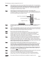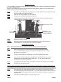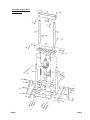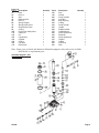
1
MINI LOG SPLITTER
6 TON
42696
ASSEMBLY & OPERATING INSTRUCTIONS
®
3491 Mission Oaks Blvd., Camarillo, CA 93011
Visit our Web Site at www.harborfreight.com
3
Revised cover page 04/06
THANK YOU for choosing a HARBOR FREIGHT TOOLS product. For future reference, please complete the
owner’s record below:
Model______________
Serial No.______________
Purchase Date_____________
SAVE THE RECEIPT, WARRANTY AND THESE INSTRUCTIONS. It is important that you read the entire
manual to become familiar with the unit BEFORE you begin assembly.
Technical Specifications
Tool Name:
Item Number:
Log Capacity:
Overall:
Handle Length:
Cylinder Capacity:
Cylinder:
Length:
Base Rails:
Base Support:
Cutter Support:
Uprights:
Retaining Pins:
Weight:
Log Splitter - Mini 6 Ton
42696
27" Long 8" Diameter
14-7/8" L x 15-1/8" W x 44-3/8" H
12"
6 Ton
Hydraulic
8"
0.160 Angle Iron
0.112" Mild Steel
0.312" Mild Steel
0.125"
0.390 OD x 2-1/2" L
34 LBS.
Safety Warnings and Precautions
WARNING: When using product, basic safety precautions should always be followed to
reduce the risk of personal injury and damage to equipment.
Read all instructions before using this product!
1.
Keep work area clean. Cluttered areas invite injuries.
2.
Keep children away. Children must never be allowed in the work area.
3.
Store idle equipment. When not in use, tools must be stored in a dry location to inhibit rust. Always lock
up tools and keep out of reach of children.
4.
Do not force tool. It will do the job better and more safely at the rate for which it was intended. Do not
use inappropriate attachments in an attempt to exceed the tool capacity.
5.
Use the right tool for the job. Do not attempt to force a small tool or attachment to do the work of a
larger industrial tool. There are certain applications for which this tool was designed. Do not modify this
tool and do not use this tool for a purpose for which it was not intended.
#42696
Page 2
6.
Use eye and ear protection. Always wear ANSI approved impact safety goggles. Wear a full face shield
if you are producing metal filings or wood chips. Wear an ANSI approved dust mask or respirator when
working around metal, wood, and chemical dusts and mists.
7.
Dress properly. Do not wear loose clothing or jewelry as they can be caught in moving parts. Protective,
electrically non-conductive clothes and non-skid footwear are recommended when working. Wear
restrictive hair covering to contain long hair.
8.
Stay alert. Watch what you are doing, use common sense. Do not operate any tool when you are tired.
9.
Check for damaged parts. Before using any tool, any part that appears damaged should be carefully
checked to determine that it will operate properly and perform its intended function.
10. Replacement parts and accessories. When servicing, use only identical replacement parts. Use of any
other parts will void the warranty. Only use accessories intended for use with this tool. Approved
accessories are available from Harbor Freight Tools.
11. Do not operate tool if under the influence of alcohol or drugs. Read warning labels on prescriptions
to determine if your judgment or reflexes are impaired while taking drugs. If there is any doubt, do not
operate the tool.
12. Observe area conditions. Do not use product in damp or wet locations. Do not expose to rain.
13. Do not overreach. Keep proper footing and balance at all times. Do not reach over or across the
Log Splitter. Never place hands or feet between the log and splitter wedge or between the log and ram
during the forward or reverse stroke.
14. Never leave the product unattended while in operation.
15. Remove adjusting keys and wrenches. Check that keys and adjusting wrenches are removed from the
tool or machine work surface before operating.
16. Never place your hands or other body parts near a hydraulic fluid leak. Never check for a leak with
your hands or other body parts. High-pressure fluid can be forced under your skin resulting in serious
injury.
17. Never attempt to split two logs on top of each other.
Warning:
The warnings, cautions, and instructions discussed in this instruction manual cannot cover all
possible conditions and situations that may occur. It must be understood by the operator that
common sense and caution are factors which cannot be built into this product, but must be
supplied by the operator.
Warning:
This product contains or produces a chemical known to the State of
California to cause cancer and birth defects (or other reproductive harm).
(California Health & Safety Code 25249.5 et seq.)
Assembly
Your Log Splitter will require complete assembly prior to operation. It is important that you read the entire
manual to become familiar with the unit BEFORE you use the Log Splitter. Before assembling your Log Splitter
be sure that you have all parts described in the Parts List.
When assembling your Log Splitter, it will be helpful to refer each of the operational Figures as well as to the
Parts List and Assembly Diagram on the last pages of this manual.
Assemble attachments based on the intended use of the Log Splitter.
Mounting Surface: The mounting surface must be flat, level and capable of supporting the weight of the Log
Splitter combined with the materials to be split.
#42696
Page 3
The following part numbers correspond to Parts List “A”.
Step 1)
Slide the Blade Assembly (#4A) onto the Upper Frame Assembly (#2A). Line up the holes in
the Blade Assembly (#4A) with those in the Upper Frame Assembly (#2A). Insert one Support
Pin (#14A) through each set of holes. With the Support Pin completely through the Blade
Assembly (#4A) and Upper Frame Assembly (#2A), insert a Hair Pin Clip (#20A) through
each Support Pin (#14A)-see Figure 1 below.
Step 2)
Slide the Upper Frame Assembly (#2A) onto the Lower Frame Assembly (#3A).
Insert one Support Pin (#13) through each set of holes. Once the Support Pin(#13) is fully
through both the Upper Frame Assembly (#2A) and the Lower Frame Assembly (#3A) insert a
Hair Pin Clip (#20) through each Support Pin (#13).
Upper Frame Assembly (#2A)
Hair Pin Clip (#20A)
Blade
Assembly (#4A)
Support Pin (#14A)
Attaching the Base
Step 1)
Figure 1
To attach the two Base Support Assemblies (#9A) to the Lower Frame Assemblies (#3A) set
one Base Support Assembly (#9A) on each side of the Lower Frame Assemblies as in
Figure 3.
Step 2)
There are 3 Hex Head Bolts (#17A) on each side. For each side, insert two of the Hex Head
Bolts (#17A) through the Base Support Assembly (#9A), through the Lower Frame Assembly
(#03A) and through the other Base Support Assembly-see Figure 3.
Step 3)
Secure in place with two Hex Nuts (#18A) on each side.
Step 4)
To the inside of each Lower Frame Assembly there is another hole in the Base Support
Assembly. Into this hole insert a Hex Head Bolt (#17A) through the Base Support
Assembly (09A), then through a Bushing (8A) and out through the second Base Support
Assembly (09A). Secure in place with Hex Nut (#18A)-see Figure 3.
Step 5
Thread a Hex Nut (#10A) onto each Hook Screw (#11A) and thread the Hook Screws up into
the bottom of Jack Support (#1A) Also thread a Nex Nut (#10A) onto the Hook Screw as it
protrudes up through the Base (#1B). See Assembly Diagram - Page 8. Connect a Spring
(#12A) between each Hook Screw (#11A), and Bushing (#8A). Adjust each Hook Screw so that
tension is equal for both Springs (#12A). Once properly adjusted, tighten the Hex Nuts (#10A),
below and above the Base (#1B), against the Base (#1B).
Step 6)
Attach each Base Assembly (#5A) and Supporting Plate (#7A) to the Lower Frame
Assemblies (#3A). Place two Supporting Plates so that the hole in the end lines up with the
hole in the Lower Frame Assembly (#3A); the Supporting Plates (#7A) will have to overlap.
Insert Hex Head Bolt (#16A) through the Supporting Plates and through the Lower Frame
Assembly (#3A) and hand tighten on Hex Nut (18A)-see Figure 3. Repeat for second side.
Step 7)
Secure the other end of each Supporting Plate (#7A) to one end of the Base Assembly (#5A)
as in Figure 3. Insert Hex Head Bolt (#15A) and tighten on Hex Nut (#18A). Tighten Hex
Nut (#18A) from Step 5. Repeat for second side.
Step 8)
Insert Hex Head Bolt (#16A) through the middle hole in the Base Assembly (#5A) and through
the Lower Frame Assembly (#3A), secure in place with Hex Nut (18A).
Step 9)
Insert Lock Pin (#22A) down through Hydraulic Jack (#6A) and through Base Support
Assembly (#9A). Insert Hair Pin Clip (#20A) through Lock Pin (#22A) to secure in place.
Warning:
#42696
Do not open the Release Valve (#4B) when the Log Splitter is supporting a load.
Page 4
Figure 3
Hex Head Bolt (#17A)
Lower Frame Assembly (#3A)
Hex Nut (#18A)
Supporting Plate (#7A)
Hex Head
Bolt (#16A)
Lock Pin (#22A)
Hair Pin Clip (#20A)
Base Support Assembly (#9A)
Bushing (#8A)
Base Assembly (#5A)
Mounting
The Base Assembly (#5) will accept 3/8" Bolts (not included).
Step 1)
Set the Log Splitter firmly on its mounting surface.
Warning:
The Log Splitter must be securely mounted to a work surface
prior to use!
Step 2)
Make certain that you can operate the Jack Handle (#19A) comfortably.
Step 3)
Mark the surface through the two holes located at the far ends of the Base Assembly (#5A).
Step 4)
Remove the Log Splitter from the surface to be mounted. Drill holes through the marked
locations.
Step 5)
Mount the unit using four bolts, lock washers, washers and nuts (in that order) sold separately.
Operation
When operating your Log Splitter, it may be helpful to refer to each of the operational Figures as well as to the
Parts List and Assembly Diagram located on the last pages of this manual.
Never force the tool or attachment to do the work of a larger industrial tool. It is designed to do the job better
and more safely at the rate for which it was intended.
Do not exceed the tools maximum capacity.
Filling the Pump Reservoir
Hydraulic Fluid: When filling the pump reservoir, make certain to use a high quality hydraulic fluid. The fluid
should be changed at every 300 hours of use.
Step 1)
Clean the area around the filler cap to remove all dust and grit.
Step 2)
With the Jack Handle (#19A) in place, turn the Jack Handle (#19A) counterclockwise. This will
retract all cylinders to their return position.
Step 3)
Remove the Filler Plug (#33B). Measure the level of fluid in the tank visually. Using a clean
funnel with a filter, fill the Reservoir (#29B) with hydraulic fluid up to the top. Replace the Filler
Plug (#33B).
#42696
Page 5
Bleeding the System
If any air becomes trapped in the system during initial connections or at a later time, the following steps should
be taken to bleed the system.
Note: Air in the system will cause the ram to rise and fall as the handle is pumped. If the ram does not fully
extend, add oil through the Filler Plug (#33B).
Step 1)
Step 2)
Place the Jack Handle (#19A) on the Release Valve. Open the Release Valve (#4B) by turning
the Jack Handle (#19A) counterclockwise.
Open the Filler Plug (#33B) on the side of the jack.
Step 3)
Pump the Jack Handle (#19A) rapidly several times.
Step 4)
Close the Release Valve (#4B) by turning the Jack Handle (#19) fully clockwise. Test the
function of the jack, and repeat, if necessary.
Handle Sleeve (#27B)
Plastic Cap
Safety Valve (#10B)
(DO NOT ADJUST)
Release
Valve (#4B)
Figure 2
Replace the Filler Plug (#33B).
Step 5)
Caution:
When not in use, make sure pressure is released by turning the Jack Handle fully
counterclockwise. This will prolong the life of the Log Splitter.
Operating the Log Splitter
Note:
Make sure the Release Valve (#4B) is turned fully clockwise to the closed position.
Step 1)
Make certain that the maximum length of each log to be split does not exceed
27". If the log exceeds this length, it must be cut to no longer than 27". The logs
diameter is not to exceed 8".
Step 2)
Place the Log between the Jack Support (#1A) and the Blade Assembly (#4A).
Step 3)
Insert the Jack Handle (#19A) into the Handle Sleeve (#27B)-see Figure 2. The Jack
Handle must fit into the Handle Sleeve (#27B) firmly. Turn the Jack Handle (#19A)
until you feel it slide securely into place.
Step 4)
Pumping the Jack Handle (#19A) up and down will raise the Jack Support up to the Blade
Assembly (4A) until the log is split.
Warning: Keep clear of the area surrounding the log while it is being split. Be alert to falling sections
of the log as it is split. Keep spectators well clear of the work area while the Log Splitter is being used.
Step 5)
Once the Log is split, slowly release the Release Valve (#4B) by turning counterclockwise
and remove the pieces from the Log Splitter. To back the Blade Assembly (#4A) off of the log,
turn the Jack Handle (#19A) counterclockwise. This will release the pressure and lower the
Hydraulic Jack.
Step 6)
Continue the preceding steps until all logs have been split.
#42696
Page 6
Maintenance
CLEANING:
After every use, wipe down the Log Splitter to remove any tree sap or dirt that has
accumulated during use. This will extend the use of the Log Splitter. Keep machined parts lightly greased.
Prevent wood, dust and debris from accumulating on the Log Splitter.
STORAGE:
Childproof the machine and work area. Make sure to use padlocks (not included) and to secure
the Log Splitter after operation.
IF THERE IS ANY QUESTION ABOUT A CONDITION BEING SAFE OR UNSAFE, DO NOT OPERATE THE TOOL.
PLEASE READ THE FOLLOWING CAREFULLY
THE MANUFACTURER AND/OR DISTRIBUTOR HAS PROVIDED THE PARTS DIAGRAM IN THIS MANUAL
AS A REFERENCE TOOL ONLY. NEITHER THE MANUFACTURER NOR THE DISTRIBUTOR MAKES ANY
REPRESENTATION OR WARRANTY OF ANY KIND TO THE BUYER THAT HE OR SHE IS QUALIFIED TO
MAKE ANY REPAIRS TO THE PRODUCT OR THAT HE OR SHE IS QUALIFIED TO REPLACE ANY PARTS
OF THE PRODUCT. IN FACT, THE MANUFACTURER AND/OR DISTRIBUTOR EXPRESSLY STATES THAT
ALL REPAIRS AND PARTS REPLACEMENTS SHOULD BE UNDERTAKEN BY CERTIFIED AND
LICENSED TECHNICIANS AND NOT BY THE BUYER. THE BUYER ASSUMES ALL RISK AND LIABILITY
ARISING OUT OF HIS OR HER REPAIRS TO THE ORIGINAL PRODUCT OR REPLACEMENT PARTS
THERETO, OR ARISING OUT OF HIS OR HER INSTALLATION OF REPLACEMENT PARTS THERETO.
Unpacking
UNPACK AND CHECK CONTENTS
When unpacking your Log Splitter, check to make sure the following parts are included. If any parts are
missing or broken, please call HARBOR FREIGHT TOOLS at 1-800-444-3353.
Parts List
Part #
Description
1A
Jack Support
2A
Upper Frame Assembly
3A
Lower Frame Assembly
4A
Blade Assembly
5A
Base Assembly
6A
Hydraulic Jack
7A
Supporting Plates
8A
Bushing
9A
Base Support Assembly
10A
Hex Nut M8
11A
Hook Screw M 8 x 90
Quantity
1
2
2
1
1
1
2
2
1
4
2
Part #
12A
13A
14A
15A
16A
17A
18A
19A
20A
21A
22A
Description
Spring
Support Pin 10 mm x 40
Support Pin 10 mm x 60
Hex Head Bolt M 10 x 20
Hex Head Bolt M 10 x 50
Hex Head Bolt M 10 x 60
Hex Nut M 10
Jack Handle
Hair Pin Clip 50 mm
Hair Pin Clip 25 mm
Lock Pin
Quantity
2
2
2
4
4
6
14
1
4
1
1
Note: Some parts are listed and shown for illustration purposes only and are not available
individually as replacement parts.
#42696
Page 7
Assembly Diagram- Main
Parts List “A”
#42696
Page 8
Parts List
Part #
Description
1B
Base
2B
Ball 1/4"
3B
Seal
4B
Release Valve
5B
Ball 1/4"
6B
Spring Plunger
7B
Spring-Safety Valve
8B
Screw-Safety Valve
9B
O-Ring
10B
Plastic Cap-Safety Valve
11B
Cotter Pin
12B
Pin
13B
Cap Washer
14B
Cylinder
15B
O-Ring
16B
Cup Seal
17B
Ram Piston
Quantity
1
3
1
1
1
1
1
1
1
1
1
1
1
1
1
1
1
Part #
18B
19B
20B
21B
22B
23B
24B
25B
26B
27B
28B
29B
30B
31B
32B
33B
34B
Description
Ram
Washer
Pump Cylinder
Cup Seal
Back-Up Ring
O-Ring
Pump Plunger
Handle
Rubber Handle
Handle Sleeve
Packing Reservoir
Reservoir
Packing Reservoir
Top Nut
O-Ring
Filler Plug
Filter
Quantity
1
1
1
1
1
1
1
1
1
1
1
1
1
1
1
1
1
Note: Some parts are listed and shown for illustration purposes only and are not available
individually as replacement parts.
Assembly Diagram- Jack
Parts List “B”
#42696
Page 9