1
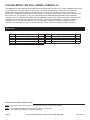
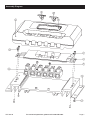
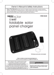
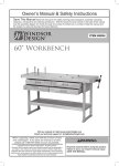
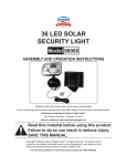
500 Watt Charge Controller
Item 68738
Read this material before using this product.
Failure to do so can result in serious injury.
SAVE THIS MANUAL.
When unpacking, make sure that the product is intact and undamaged.
If any parts are missing or broken, please call 1-800-444-3353 as soon as possible.
Visit our website at: http://www.harborfreight.com
Email our tech support at: [email protected]
Copyright© 2011 by Harbor Freight Tools®. All rights reserved. No portion of this manual or any artwork contained herein may be reproduced in any shape
or form without the express written consent of Harbor Freight Tools. Diagrams within this manual may not be drawn proportionally. Due to continuing
improvements, actual product may differ slightly from the product described herein. Tools required for assembly and service may not be included.
IMPORTANT SAFETY
INFORMATION
In this manual, on the labeling, and all other
information provided with this product:
This is the safety alert symbol. It is
used to alert you to potential personal
injury hazards. Obey all safety
messages that follow this symbol
to avoid possible injury or death.
DANGER indicates a hazardous situation which, if
not avoided, will result in death or serious injury.
WARNING indicates a hazardous situation which, if
not avoided, could result in death or serious injury.
CAUTION, used with the safety alert symbol,
indicates a hazardous situation which, if not
avoided, could result in minor or moderate injury.
Installation Precautions
1. Exercise special caution if working on roof
or another high location. Keep proper footing
and balance at all times. Follow ladder supplier’s
precautions whenever working near or on a ladder.
2. Install all sensitive electrical components
(including wiring connections, regulator,
and battery) inside a weatherproof
enclosure to prevent electric shock.
3. Do not wire multiple panels in series. If you
need to connect two or more solar panels together,
this work must be done by a qualified electrician
unless they are connected through a regulator.
4. This solar panel kit is not designed for tie-in to a
grid. Only a licensed electrician and a licensed
building contractor can safely design and implement
a grid tie-in system. Any grid tie-in system must
meet all applicable building and electrical codes,
and must meet standards established by the area
power company. Improper grid tie-in can result in
electrocution, fire, and other serious personal injury
and property damage. An incorrectly installed grid
tie-in system can cause feedback voltage, resulting
in electrocution of electrical utility workers.
5. Do not stand on or otherwise
apply pressure to panel.
6. Handle solar panel with care,
edges may be sharp.
7. Do not focus light on panel.
NOTICE is used to address practices
not related to personal injury.
CAUTION, without the safety alert symbol, is used to
address practices not related to personal injury.
WARNING Read all safety warnings and
instructions. Failure to follow the warnings and
instructions may result in electric shock, fire and/
or serious injury.
Save all warnings and instructions for
future reference. The warnings, precautions,
and instructions discussed in this instruction
manual cannot cover all possible conditions and
situations that may occur. It must be understood
by the operator that common sense and caution
are factors which cannot be built into this
product, but must be supplied by the operator.
Page 2
8. Install components with enough
space to allow proper cooling.
9. This product may occasionally produce more
current and/or voltage than its rated output.
Increase output ratings by 25% when determining
component required voltage and amperage
ratings. Refer to Section 690-8 of the National
Electrical Code for an additional multiplying factor of
125 percent (80 percent derating) which may apply.
For technical questions, please call 1-800-444-3353.
SKU 68738
10. Panel must be connected using UL listed outdoor
rated wire of the correct thickness (gauge) for the
amperage rating and length (see warning number
9 also). Follow the guidelines in the chart below:
Current
in Amps
0-5
6-7
8
10
11-12
15
18
20
22-24
30
5'
Maximum Length
10'
15'
20'
25'
18
18
18
18
16
16
16
14
18
16
16
14
14
12
16
14
12
12
10
10
Minimum Wire Gauge
11. Install an appropriate charge controller/regulator
to regulate output and prevent damage. Do not
attach panel to battery or power grid without proper
regulator, inverter, and/or charge controller.
12. Install and use according to applicable
National Electrical Code (NEC) standards.
13. This panel is not rated for use as fire-resistant
roofing. If installing on a roof, install only over a fire
resistant roof covering rated for the application.
14. Verify that installation surface has no hidden
utility lines before drilling or driving screws.
15. Install only according to these instructions.
Improper installation can create hazards.
16. Wear ANSI-approved safety goggles and heavyduty work gloves during installation. Do not
wear jewelry or metal watches when working
near solar panels, wiring or batteries.
17. Handle panel with care. Glass may break or a
sharp edge may be exposed during movement.
18. Keep installation area clean and well lit.
19. Install out of reach of children.
20. Keep bystanders out of the area during installation.
21. Do not install when tired or when under
the influence of drugs or medication.
22. Use in 12 VDC systems only.
Battery Precautions
3. Charge, store, and maintain batteries
according to supplier’s instructions.
Service Precautions
1. Before service, maintenance, or cleaning:
a. Dry solar panels and outdoor
wiring thoroughly while wearing
electrically insulated gloves.
b. Cover all solar panels with an opaque
cover, such as a blanket.
c. Disconnect all solar panels.
d. Disconnect all batteries.
2. Do not service during rain, fog, or
any other wet/humid weather.
3. Do not stand on or otherwise
apply pressure to panel.
4. Do not allow children to play with or near
this item or electrical components.
5. Inspect at least monthly; do not use if damaged,
parts are loose, water is found inside the
housing, electrical insulation is cracked or
damaged, or connections are loose.
6. Maintain product labels and nameplates.
These carry important safety information.
If unreadable or missing, contact
Harbor Freight Tools for a replacement.
7. WARNING: Handling the cord on this product will
expose you to lead, a chemical known to the State
of California to cause cancer, and birth defects or
other reproductive harm. Wash hands after handling.
(California Health & Safety Code § 25249.5, et seq.)
SAVE THESE
INSTRUCTIONS.
Specifications
Max. Input Current
500 Watt
Rated Output
12VDC
Over Charge Voltage 14.5V + 0.4V
Note: Output will decrease as the panel gets hotter
than room temperature (~70° F). Angle, solar intensity,
cloud cover and other factors will effect output.
1. Wear splash-resistant ANSI-approved
safety goggles and electrically insulated
gloves while working near batteries.
2. Use an appropriate charge controller
whenever connected to battery.
SKU 68738
For technical questions, please call 1-800-444-3353.
Page 3
Wiring
Installation
Read the ENTIRE IMPORTANT SAFETY
INFORMATION section at the beginning of
this manual including all text under
subheadings therein before set up or use
of this product:
Note: Only a licensed electrician and a licensed building
contractor can safely design and implement a grid
tie-in system. Any grid tie-in system must meet all
applicable building and electrical codes, and must meet
standards established by the area power company.
Note: For additional information regarding the
parts listed in the following pages, refer to the
Assembly Diagram near the end of this manual.
1. Run wires from panels, through weatherproof
grommets and into enclosure where charge
controller/regulator is located. Use wires
of the proper size and rating and use twist
connectors (not included) to connect wires.
Identifying Port Connections
2. Secure all connections using terminals, or solder
all wire splices to ensure good connections.
1. The battery should be connected to the ports
that show the battery icon with a + and symbol. Please note that “+” stands for positive
pole and “-” stands for the negative pole.
2. The DC load should be connected to the
ports that show the light bulb icon and the
positive (+) and negative (-) symbols.
3. The Solar Panel should be connected to the ports
marked with the solar panel symbol and the positive
(+) and negative (-) symbols.
WARNING! Follow indicated polarity
for all connections and verify all
connections are secure before use.
3. Weatherproof all connections and route the wire in
a way that it will not be torn loose from the panel.
4. Allow system to charge according to
the solar panel’s instructions.
Operation
The Display Button (marked by the triangle symbol)
works in a cycle pattern. See below.
Making Connections
WARNING! When disconnecting or connecting,
always follow this sequence:
Disconnecting:
1. Disconnect the positive and then
negative ports of the Solar Panel.
2. Turn off the Load Switch (designated by the
bulb icon), then disconnect the load ports.
3. Disconnect the positive and then negative ports.
WARNING! Do not disconnect battery
before disconnecting solar panel.
Connecting:
1. Connect the battery ports, first
positive and then negative.
2. Connect the solar panel ports, first
positive and then negative.
3. Connect the load ports, first
positive and then negative.
Display Button
Load Switch
By pressing the button, the LED will toggle through the
three different modes:
a. Battery Voltage (12V)
b. Output Current to Load (18A)
c. Solar Charge Current (18A)
1.
Mode 1 / Battery Voltage:
The LCD will show the working voltage of the battery
(12V, for example)
Pressing the Load Switch in this mode will NOT
change the display on the LED.
2.
Press the Display Button again (Mode 2) and the
LED will show the output current from battery to
load (18A).
If the Load Switch is ON, the display will not change.
If the Load Switch is OFF, the LED will show 00.0 A.
Page 4
For technical questions, please call 1-800-444-3353.
SKU 68738
If the overload discharge is triggered in this mode,
the load output will be cut off. Pressing the Load
Switch will cause an alarm to sound.
Note: It is normal to see up to 20% degradation in
amorphous silicon solar panel performance within the first
6 months before the amorphous coating stabilizes.
Once system recovers from over discharge or
overload, press the Load Switch to reset the load
output function.
Cleaning
3. Press the Display Button a third time and the LED
will show the charging current from the solar panel
to the battery (18A).
Pressing the Switch Button in this mode will change
the LED display.
4.
WARNING! Connect Battery Clamps according
to correct polarity (red for positive and black for
negative.) Do not short circuit the Battery Clamp.
5.
CAUTION: When installing Charge Controller to
Solar System, always verify that battery voltage and
solar panel voltage are matching. The input current
from the Solar Panel should not exceed the max.
solar input current limit of the Charge Controller.
6.
NOTE: It is normal for the current on LED display
to change. Since the battery is changing between
charging and discharging status when in overcharger protection, the current variation is normal.
Clean and inspect all parts of the Solar
Power System MONTHLY, or more
frequently to maintain peak efficiency.
1. Wear electrically insulated gloves and
ANSI-approved safety goggles. Dry solar
panel and outdoor wiring thoroughly.
2. Cover solar panels with an opaque
cover, such as a blanket.
3. Disconnect solar panel and batteries.
4. Clean solar panel with mild, non-abrasive
cleanser and soft cloth and paper towels. Do
not clean with brushes or abrasive cleaners.
5. Inspect the general condition of the Solar Power
System, including panel, batteries, controllers,
and mounting connections. Check for loose
hardware, wiring insulation damage or weathering,
cracked glass, open housing, cracked or broken
parts, loose or corroded contacts, and any other
condition that may affect its safe operation.
6. Inspect and maintain batteries according
to supplier’s instructions.
Servicing
Procedures not specifically explained in this
manual must be performed by
a qualified technician.
Adjustment
To increase efficiency:
1. In the Winter, increase the panel’s angle by 10°.
TO PREVENT SERIOUS INJURY
FROM ELECTRIC SHOCK:
Before service, maintenance or cleaning:
a. Dry Charge Controller and outdoor
wiring thoroughly while wearing
electrically insulated gloves.
2. In the Summer, decrease the angle by up to 10°.
3. In the Spring and Fall, keep the panel at the angle
recommended by solar panel’s instruction manual.
b. Cover solar panel with an opaque
cover, such as a blanket.
c. Disconnect solar panel after use.
d. Disconnect all batteries after use.
TO PREVENT SERIOUS INJURY FROM
ELECTRIC SHOCK OR CUTS:
Do not use damaged Charge Controller.
If wiring insulation is damaged or
weathered, solar panel glass is cracked,
or housing is opened, have the problem corrected
before further use.
SKU 68738
For technical questions, please call 1-800-444-3353.
Page 5
PLEASE READ THE FOLLOWING CAREFULLY
THE MANUFACTURER AND/OR DISTRIBUTOR HAS PROVIDED THE PARTS LIST AND ASSEMBLY DIAGRAM
IN THIS MANUAL AS A REFERENCE TOOL ONLY. NEITHER THE MANUFACTURER OR DISTRIBUTOR
MAKES ANY REPRESENTATION OR WARRANTY OF ANY KIND TO THE BUYER THAT HE OR SHE IS
QUALIFIED TO MAKE ANY REPAIRS TO THE PRODUCT, OR THAT HE OR SHE IS QUALIFIED TO REPLACE
ANY PARTS OF THE PRODUCT. IN FACT, THE MANUFACTURER AND/OR DISTRIBUTOR EXPRESSLY
STATES THAT ALL REPAIRS AND PARTS REPLACEMENTS SHOULD BE UNDERTAKEN BY CERTIFIED AND
LICENSED TECHNICIANS, AND NOT BY THE BUYER. THE BUYER ASSUMES ALL RISK AND LIABILITY
ARISING OUT OF HIS OR HER REPAIRS TO THE ORIGINAL PRODUCT OR REPLACEMENT PARTS
THERETO, OR ARISING OUT OF HIS OR HER INSTALLATION OF REPLACEMENT PARTS THERETO.
Parts List
Part
1
2
3
4
5
Description
Cover
Switch
Board Screws
PCB Board
Output Screws
Qty.
1
2
4
1
2
Part
6
7
8
9
Description
Base
Base Screws
Output Jack
Display Board
Qty.
1
4
1
1
Record Product’s Serial Number Here:
Note: If product has no serial number, record month and year of purchase instead.
Note: Some parts are listed and shown for illustration purposes only,
and are not available individually as replacement parts.
Page 6
For technical questions, please call 1-800-444-3353.
SKU 68738
Assembly Diagram
SKU 68738
For technical questions, please call 1-800-444-3353.
Page 7
90 Day Warranty
Harbor Freight Tools Co. makes every effort to assure that its products meet high quality and durability standards,
and warrants to the original purchaser that this product is free from defects in materials and workmanship for the
period of 90 days from the date of purchase. This warranty does not apply to damage due directly or indirectly,
to misuse, abuse, negligence or accidents, repairs or alterations outside our facilities, criminal activity, improper
installation, normal wear and tear, or to lack of maintenance. We shall in no event be liable for death, injuries
to persons or property, or for incidental, contingent, special or consequential damages arising from the use of
our product. Some states do not allow the exclusion or limitation of incidental or consequential damages, so the
above limitation of exclusion may not apply to you. THIS WARRANTY IS EXPRESSLY IN LIEU OF ALL OTHER
WARRANTIES, EXPRESS OR IMPLIED, INCLUDING THE WARRANTIES OF MERCHANTABILITY AND FITNESS.
To take advantage of this warranty, the product or part must be returned to us with transportation charges
prepaid. Proof of purchase date and an explanation of the complaint must accompany the merchandise.
If our inspection verifies the defect, we will either repair or replace the product at our election or we may
elect to refund the purchase price if we cannot readily and quickly provide you with a replacement. We will
return repaired products at our expense, but if we determine there is no defect, or that the defect resulted
from causes not within the scope of our warranty, then you must bear the cost of returning the product.
This warranty gives you specific legal rights and you may also have other rights which vary from state to state.
3491 Mission Oaks Blvd. • PO Box 6009 • Camarillo, CA 93011 • (800) 444-3353