1
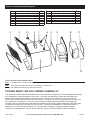
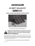
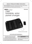
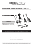
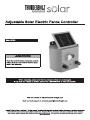
IMPORTANT SAFETY
INFORMATION
In this manual, on the labeling, and all other
information provided with this product:
This is the safety alert symbol. It is
used to alert you to potential personal
injury hazards. Obey all safety
messages that follow this symbol
to avoid possible injury or death.
DANGER indicates a hazardous situation which, if
not avoided, will result in death or serious injury.
WARNING indicates a hazardous situation which, if
not avoided, could result in death or serious injury.
CAUTION, used with the safety alert symbol,
indicates a hazardous situation which, if not
avoided, could result in minor or moderate injury.
NOTICE is used to address practices
not related to personal injury.
CAUTION, without the safety alert symbol, is used
to address practices not related to personal injury.
WARNING Read all safety warnings and
instructions. Failure to follow the warnings and
instructions may result in electric shock, fire and/
or serious injury.
Save all warnings and instructions for
future reference. The warnings, precautions,
and instructions discussed in this instruction
manual cannot cover all possible conditions and
situations that may occur. It must be understood
by the operator that common sense and caution
are factors which cannot be built into this
product, but must be supplied by the operator.
Installation Precautions
1. Use as intended for animal control only.
2. Only a qualified, certified electrician
should install the Fence Control.
3. Do not connect any other device, such as a
poultry or cattle trainer, to a fence that is already
connected to the Fence Control. Do not connect
more than one fence controller to the same fence.
Page 2
4. Avoid accidental electric shock. Do not install
an electric fence below high voltage power plant
transmission lines. Do not touch or attempt to
climb over a fence that is electrically charged.
Do not use more than one Fence Control on the
same fence. Install “Danger! Electric Fence!
Risk of Electrical Shock if Touched!” signs
in visible areas to identify the electrified wires.
Inform everyone who might possibly come in contact
with the electrically charged fence about its location.
Instruct everyone who might possibly come in
contact with the electrically charged fence how to
disconnect the Fence Control in case of emergency.
5. Do not electrify barbed wire.
People or animals may get tangled in the barbed
wire and be unable to move clear of the fence.
6. Install all sensitive electrical components
(including wiring connections, regulator,
and battery) inside a weatherproof
enclosure to prevent electric shock.
7. Do not use any means of charging the
Battery (10) or energizing fence other
than the Solar Panel (2) or a constantpotential-current-limited battery charger
rated at 6VDC at 4.5 Amps per hour.
8. Do not overcharge the Battery when
using a constant-potential-current-limited
battery charger. To use a battery charging
system other than the Solar Panel, the Battery
must be removed from the Fence Control.
9. Do not focus light on panel.
10. Install components with enough
space to allow proper cooling.
11. This product may occasionally produce more
current and/or voltage than its rated output.
Increase output ratings by 25% when
determining component required voltage
and amperage ratings. Refer to Section
690-8 of the National Electrical Code for an
additional multiplying factor of 125 percent
(80 percent derating) which may apply.
12. Do not use solar panel as power supply for
anything other than fence controller.
13. Verify that installation surface has no hidden
utility lines before drilling or driving screws.
14. Install only according to these instructions.
Improper installation can create hazards.
15. Wear ANSI-approved safety goggles and
heavy-duty work gloves during installation.
Do not wear jewelry or metal watches when
working near solar panels, wiring or batteries.
16. Handle panel with care. Glass may break or a
sharp edge may be exposed during movement.
For technical questions, please call 1-888-866-5797.
Item 47454
17. Keep installation area clean and well lit.
18. Install out of reach of children.
19. Keep bystanders out of the area during installation.
20. Do not install when tired or when under
the influence of drugs or medication.
21. People with pacemakers should consult their
physician(s) before installation and/or service.
Electromagnetic fields in close proximity to
heart pacemaker could cause pacemaker
interference or pacemaker failure.
Service Precautions
1. Do not service or approach fence during rain
or lightning storms. Do not service during
rain, fog, or any other wet/humid weather.
2. Before service, maintenance, or cleaning:
a. Dry solar panel and outdoor wiring thoroughly
while wearing electrically insulated gloves.
b. Cover solar panel with an opaque
cover, such as a blanket.
c. Disconnect solar panel.
d. Disconnect all batteries.
3. To avoid fire, turn off fence (and use other animal
control means) in extremely dry weather.
4. In winter the battery may become drained.
Swap the battery with an identical, fully charged
battery as needed to maintain power to the fence.
5. Do not allow children to play with or near
this item or electrical components.
6. Inspect at least monthly; do not use if damaged,
parts are loose, water is found inside the housing,
electrical insulation is cracked or damaged,
or connections are loose.
7. Do not modify Fence Controller. It has built in safety
features and could become dangerous if modified.
8. Maintain product labels and nameplates.
These carry important safety information.
If unreadable or missing, contact
Harbor Freight Tools for a replacement.
9. WARNING: Handling the cord on this product will
expose you to lead, a chemical known to the State
of California to cause cancer, and birth defects or
other reproductive harm. Wash hands after handling.
(California Health & Safety Code § 25249.5, et seq.)
SAVE THESE
INSTRUCTIONS.
Item 47454
Specifications
Input Voltage
Output Voltage
Rated Wattage
(in full sunlight)
Battery Type
Range of
Fence Control
8.7 VDC
8KV +/- 2KV
1.3 W
6V, 4.5Ah, Lead-acid
3 to 5 Miles (Single Strand Wire)
Note: Output will decrease as the panel gets hotter
than room temperature (~70° F). Angle, solar intensity,
cloud cover and other factors will effect output.
Installation
IMPORTANT! Read the ENTIRE IMPORTANT
SAFETY INFORMATION section at the beginning of
this manual including all text under subheadings
therein before set up or use of this product:
Note: For additional information regarding the
parts listed in the following pages, refer to the
Assembly Diagram near the end of this manual.
DISCLAIMER
Due to the unpredictable nature of large
animals, their ownership and confinement
creates certain liability risks that are
the responsibility of their owners.
Harbor Freight Tools makes no
guarantee, expressed or implied,
that the use of this product will prevent
potential property damage or injury
to humans or animals caused by
an attempt to contain such animals.
Mounting Fence Control On
Horizontal Or Vertical Surface
1. CAUTION! Before mounting, verify Power
Switch (5) is in the OFF position.
2. To mount Solar Fence Controller onto a
wood surface, place the Fence Control against
the desired location on the wood surface. Use
the two mounting holes located at the top of the
Main Body (4) as a template with which to mark
two holes to be drilled into the wood surface. Set
aside the Solar Fence Contoller, and drill the
two holes in the wood surface. Use two wood
screws (not included) of appropriate diameter
and length to secure the Solar Fence Controller
to the wood surface. See Figure 1, below.
For technical questions, please call 1-888-866-5797.
Page 3
Mounting
Holes
Adjusting
Frame (3)
The solar panel should face towards south to expose
the solar panel to the maximum possible sunlight.
4. Connect one end of an appropriate length of
12 AWG Insulated Wire to the Ground Rod, using
a Ground Clamp (not included). See Figure 2.
5. Connect the other end of the 12 Gauge Insulated
Wire to the Black/Negative Terminal (6) of
the Solar Fence Controller. See Figure 2.
Main
Body (4)
Connecting Fence Line to
Solar Fence Controller
Figure 1
3. To mount Solar Fence to a metal surface, place
the Solar Fence Controller against the desired
location on the metal surface. Use the two mounting
holes located at the top of the Main Body as a
template with which to mark two holes to be drilled
all the way through the metal surface. Set aside
the Solar Fence Controller, and drill the two holes
through the metal surface. Then, use two machine
bolts of appropriate diameter and length, two lock
washers, and two nuts (not included) to secure
the Solar Fence Controller to the metal surface.
Properly Grounding
Fence Control
NOTE: The Switch Cover (13) must be
removed from the Power Switch when the
Solar Fence Controller is not in operation.
2. Splice one end of an appropriate length
of 12-1/2 Gauge Insulated Wire onto
the Fence Line. See Figure 2.
3. Connect the other end of the 12 Gauge Insulated
Wire to the Red/Positive Terminal (6) of the
Solar Fence Controller. See Figure 3, below.
Figure 3
1. Ground Rod (not provided) is required to properly
ground Solar Fence Controller. A Ground Rod should
be made of copper, galvanized pipe, or a steel
rod driven approximately six to eight feet into the
ground as near to Solar Fence Controller as possible.
2. CAUTION! Do not use an existing Ground Rod
that is hooked up to other electrical systems
or to a water pipe. See Figure 2, below.
Red/Positive
Terminal (6)
1. CAUTION! Prior to connecting the Fence Line
to the Solar Fence Controller, make sure its
Power Switch (5) is in the OFF position.
Angle Adjusting Frame (3)
Solar Panel (2)
Red/Positive
Terminal (6)
Black/Negative
Terminal (6)
Switch
Cover (13)
Indicating
Lamp (7)
Power
Switch (5)
Red/Positive
Wire
Black/Negative
Terminal (6)
12 AWG Insulated
Wire (not included)
12 AWG
Wire
Fence Wire
Battery
Compartment
Screw
Door (11)
(12)
Black/
Negative Wire
Battery
(10)
Main
Body (4)
NOTE: The solar panel should face the Sun, and not
be blocked by shadows. The location should allow
the panel to be protected from accidental damage.
Figure 2
Ground Rod/Ground Clamp
(not included)
3. The front side of the solar panel (with terminals
and switch/key) should face the sunlight.
Page 4
For technical questions, please call 1-888-866-5797.
Item 47454
4. Angle face of Controller Frame toward true
south1 according to chart that follows:
Latitude
0-4°
5-20°
21-45°
46-64°
65° or more
Solar Panel Angle
10°
Latitude + 5°
Latitude + 10°
Latitude + 15°
80°
Wiring
Note: Only a licensed electrician and a licensed building
contractor can safely design and implement a grid
tie-in system. Any grid tie-in system must meet all
applicable building and electrical codes, and must meet
standards established by the area power company.
1. Run wires from panels, through weatherproof
grommets and into enclosure where charge
controller/regulator is located. Use wires
of the proper size and rating and use Twist
Connectors (not included) to connect wires.
2. Secure all connections using terminals, or solder
all wire splices to ensure good connections.
3. Weatherproof all connections and route the wire in
a way that it will not be torn loose from the panel.
Operation
NOTE: To operate Solar Fence Controller, the Switch
Cover (13) must be inserted into Power Switch (5) cover
and the Power Switch must be lifted up to ON position.
1. Once installed, allow Solar Fence Controller
to charge at least eight hours in full, direct
sunlight in order to fully charge the Battery
(10). If necessary, adjust the Solar Panel
to increase the pickup of solar energy.
NOTE: After making sure that all safety warnings
and precautions are adhered to, the Solar
Fence Controller is ready to be activated.
2. When the Battery is fully charged, place the
Switch Cover (13) on the Power Switch and
turn the Power Switch to its “ON” position.
3. Observe the Indicating Lamp (7).
A blinking Indicating Lamp shows that
the electrical output is working properly.
The fence is now electrically activated.
NOTE: If the Indicating Lamp does not blink,
turn the Power Switch to its OFF position.
Have a qualified, certified electrician disconnect both
12 Gauge Insulated Wires from the Fence Control.
Then, turn the Power Switch to its ON position.
If the Indicating Lamp does blink, the problem is with
the fence. If the Indicating Lamp does not blink, the
problem is with the Solar Fence Controller or its Battery.
1 Angle towards true north if installed
in southern hemisphere.
Item 47454
4.
TO AVOID FIRE, turn off fence
(and use other animal control means)
in extremely dry weather.
NOTE: In winter the battery may become drained.
Swap the battery with an identical, fully charged
battery as needed to maintain power to the fence.
(See Battery Replacement/Removal on page 6.)
Recommended Electric Fence Accessories
NOTE: For personal safety, it is recommended that only
a qualified, certified, electrician install fence accessories.
Posts
Use posts made of treated wood,
steel, aluminum or fiberglass.
Fence Wire
Use size 20 through 9 American wire gauge.
Use a smooth, galvanized steel electric fence wire.
Or use an aluminum wire which conducts electricity four
times better than steel. Or use a plastic/metallic wire
according to the manufacturer’s recommendations.
Note: Do not mix different wire types.
Different wire types will interact electrically, loosen
connections and reduce the fence’s effectiveness.
Insulated Wire
Use size 12 Gauge for running under roads and under
gates. If desired, use insulated wire with PVC tubing.
Insulators
Use standard insulators on rod-type line support posts,
or on wooden posts. At the starting point,
and at fence corners, use corner post insulators.
Always insulate wooden posts.
Do not staple fence wire directly to the post.
Splices
Two types of splicing may be used; hand splicing, or the
use of specially designed splicing bolts and connectors.
Gates
A simple gate can be constructed from a single “hot”
wire line with the use of an insulated gate handle.
However, disconnecting the gate handle also disconnects
electric flow in the fence. A typical gate can be used
without interfering with electric flow in fence by running
an insulated wire under gate, beneath ground level.
A “hot” wire line may be mounted on a typical gate itself
to prevent animals from rubbing or pushing through gate.
For technical questions, please call 1-888-866-5797.
Page 5
Servicing
Procedures not specifically explained in
this manual must be performed by
a qualified technician.
2. To remove Battery, loosen and remove Screw (12)
located at rear of Fence Control.
Open Battery Compartment Door (11).
Pull Battery out of unit and disconnect Black wire
that is connected to the negative battery terminal.
TO PREVENT SERIOUS INJURY
FROM ELECTRIC SHOCK:
Before service, maintenance or cleaning:
a. Dry solar panel and outdoor wiring thoroughly
while wearing electrically insulated gloves.
b. Cover all solar panels with an opaque
cover, such as a blanket.
Battery
Compartment
Door (11)
c. Disconnect all solar panels.
Figure 4
d. Disconnect all batteries.
TO PREVENT SERIOUS INJURY FROM
ELECTRIC SHOCK OR CUTS:
Do not use damaged solar panel.
If wiring insulation is damaged or
weathered, glass is cracked, or housing
is opened, have problem corrected before
further use. Check to make sure the “Danger! Electric
Fence! Risk of Electrical Shock if Touched!” signs are
still up and visible in areas to identify the electrified wires.
Check for loose, cracked or broken parts, loose or
damaged electrical connections, and any other condition
that may affect the safe operation of this equipment.
If a problem occurs, immediately turn Power Switch to its
OFF position and remove the Switch Lock.
Have the problem corrected by
a qualified, certified electrician before further use.
Do not use damaged equipment.
Battery Replacement/Removal
NOTE: In winter the battery may become drained.
Swap the battery with an identical, fully charged
battery as needed to maintain power to the fence.
1. To use battery charging system other than
the Solar Panel (2), the Battery must be
removed from the Solar Fence Charger.
CAUTION! Do not use any means of charging Battery
other than Solar Panel or a constant-potentialcurrent-limited charger rated at 6VDC at 4.5 amps.
Screw (12)
3. Disconnect Red wire connected to positive
battery terminal. Follow battery charger
manufacturer’s instructions to fully charge Battery.
Once Battery is fully charged, reconnect Black
wire to negative Battery terminal and reconnect
Red wire to positive Battery terminal.
4. Reinstall Battery in Solar Fence Charger unit and
close Battery Compartment Door. Replace Screw
to lock the Battery Compartment Door in position.
Cleaning
Clean and inspect the Solar Fence Charger MONTHLY,
or more frequently to maintain peak efficiency.
1. Wear electrically insulated gloves
and ANSI-approved safety goggles.
Dry solar panel and outdoor wiring thoroughly.
2. Clean solar panel with mild, non-abrasive
cleanser and soft cloth and paper towels.
Do not clean with brushes or abrasive cleaners.
3. Inspect general condition of Solar Fence system
(panel, batteries and mounting). Check for loose
hardware, wiring insulation damage or weathering,
cracked glass, open housing, cracked or broken
parts, loose or corroded contacts, and any other
condition that may affect its safe operation.
4. Inspect and maintain batteries according
to supplier’s instructions.
Adjustment
To increase efficiency:
1. In the Winter, increase the panel’s angle by 10°.
2. In the Summer, decrease the angle by up to 10°.
3. In the Spring and Fall, keep the panel at
the angle recommended on page 5.
Page 6
For technical questions, please call 1-888-866-5797.
Item 47454
Parts List and Assembly Diagram
Part
1
2
3
4
5
6
7
2
Description
Qty.
Panel Fixing Plate
Solar Panel
Angle Adjusting Frame
Main Body
Power Switch
Terminals
Indicating Lamp
3
13
1
1
1
1
1
1
2
1
5
7
Part
8
9
10
11
12
13
Description
PCB
Bottom Case
Battery (6V)
Battery Compartment Door
Screw
Switch Cover
6 8
9
4
10
Qty.
1
1
1
1
6
1
11
12
Record Product’s Serial Number Here:
Note:
If product has no serial number, record month and year of purchase instead.
Note: Some parts are listed and shown for illustration purposes only,
and are not available individually as replacement parts.
PLEASE READ THE FOLLOWING CAREFULLY
THE MANUFACTURER AND/OR DISTRIBUTOR HAS PROVIDED THE PARTS LIST AND ASSEMBLY DIAGRAM
IN THIS MANUAL AS A REFERENCE TOOL ONLY. NEITHER THE MANUFACTURER OR DISTRIBUTOR
MAKES ANY REPRESENTATION OR WARRANTY OF ANY KIND TO THE BUYER THAT HE OR SHE IS
QUALIFIED TO MAKE ANY REPAIRS TO THE PRODUCT, OR THAT HE OR SHE IS QUALIFIED TO REPLACE
ANY PARTS OF THE PRODUCT. IN FACT, THE MANUFACTURER AND/OR DISTRIBUTOR EXPRESSLY
STATES THAT ALL REPAIRS AND PARTS REPLACEMENTS SHOULD BE UNDERTAKEN BY CERTIFIED AND
LICENSED TECHNICIANS, AND NOT BY THE BUYER. THE BUYER ASSUMES ALL RISK AND LIABILITY
ARISING OUT OF HIS OR HER REPAIRS TO THE ORIGINAL PRODUCT OR REPLACEMENT PARTS
THERETO, OR ARISING OUT OF HIS OR HER INSTALLATION OF REPLACEMENT PARTS THERETO.
Item 47454
For technical questions, please call 1-888-866-5797.
Page 7
Limited 90 Day Warranty
Harbor Freight Tools Co. makes every effort to assure that its products meet high quality and durability standards,
and warrants to the original purchaser that this product is free from defects in materials and workmanship for the
period of 90 days from the date of purchase. This warranty does not apply to damage due directly or indirectly,
to misuse, abuse, negligence or accidents, repairs or alterations outside our facilities, criminal activity, improper
installation, normal wear and tear, or to lack of maintenance. We shall in no event be liable for death, injuries
to persons or property, or for incidental, contingent, special or consequential damages arising from the use of
our product. Some states do not allow the exclusion or limitation of incidental or consequential damages, so the
above limitation of exclusion may not apply to you. THIS WARRANTY IS EXPRESSLY IN LIEU OF ALL OTHER
WARRANTIES, EXPRESS OR IMPLIED, INCLUDING THE WARRANTIES OF MERCHANTABILITY AND FITNESS.
To take advantage of this warranty, the product or part must be returned to us with transportation charges
prepaid. Proof of purchase date and an explanation of the complaint must accompany the merchandise.
If our inspection verifies the defect, we will either repair or replace the product at our election or we may
elect to refund the purchase price if we cannot readily and quickly provide you with a replacement. We will
return repaired products at our expense, but if we determine there is no defect, or that the defect resulted
from causes not within the scope of our warranty, then you must bear the cost of returning the product.
This warranty gives you specific legal rights and you may also have other rights which vary from state to state.
3491 Mission Oaks Blvd. • PO Box 6009 • Camarillo, CA 93011 • 1-888-866-5797