1
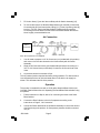
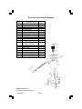
PNEUMATIC DUST COLLECTOR
2448
ASSEMBLY AND OPERATING INSTRUCTIONS
®
3491 Mission Oaks Blvd., Camarillo, CA 93011
Visit our Web site at http://www.harborfreight.com
Copyright © 2003 by Harbor Freight Tools®. All rights reserved. No portion of this manual or any
artwork contained herein may be reproduced in any shape or form without the express written consent
of Harbor Freight Tools®.
For technical questions and replacement parts, please call 1-800-444-3353
Specifications
ITEM
Max. Working Pressure
Overall Dimensions
Castor Dimensions
Tank Dimensions
Filter
Compatibility
Net Weight
DESCRIPTION
125 PSI
21-1/2” Triangulation at Wheels x 30-3/4”H
Qty 3, Swivel Housing w/2” Dia. x 7/8” Wheels
2-7/8” Dia. to 11-1/2” Dia. x 20-1/2”H
x 3/16” Thick at top
Paper, 30 Micron capacity, one year lifespan
if cleaned with blow gun after each use
Can be used with any 10-60 Gallon Abrasive
Blast Cabinets with a 1-1/4” Dia. Outlet
18.8 Lbs.
Save This Manual
You will need the manual for the safety warnings and precautions, assembly
instructions, operating and maintenance procedures, parts list and diagram. Keep
your invoice with this manual. Write the invoice number on the inside of the front
cover. Keep the manual and invoice in a safe and dry place for future reference.
Safety Warnings and Precautions
WARNING: When using this product, basic safety precautions should always
be followed to reduce the risk of personal injury and damage to equipment.
Read all instructions before using this product!
1.
Keep children away. This product is not a toy. Do not let children play with
this product or its attachments. Keep them away from all electrical cords.
2.
Store idle equipment. Store this product in a dry location when not in use,
and keep away from children.
3.
Do not force product. It will do the job better and more safely at the rate
for which it was intended. Do not use inappropriate attachments in an
attempt to exceed the product capacity.
4.
Use the right product for the job. Do not attempt to force a small product
or attachment to do the work of a larger industrial product. There are certain
applications for which this product was designed. Do not modify this product
and do not use this product for a purpose for which it was not intended.
5.
Dress properly. Do not wear loose clothing or jewelry as it can be caught in
moving parts. Wear restrictive hair covering to contain long hair.
6.
Do not overreach. Keep proper footing and balance at all times.
7.
Maintain product with care. Inspect regularly for safer performance.
Follow instructions for changing accessories.
SKU 2448
Page 2
8.
Disconnect power. Unplug product when not in use.
9.
Avoid unintentional starting. Be sure the switch is in the Off position when
not in use and before plugging in.
10. Stay alert. Watch what you are doing, use common sense. Do not operate
any product when you are tired.
11. Check for damaged parts. Before using any product, any part that appears
damaged should be carefully checked to determine that it will operate
properly and perform its intended function. Check for alignment and binding
of moving parts; any broken parts or mounting fixtures; and any other
condition that may affect proper operation. Any part that is damaged should
be properly repaired or replaced by a qualified technician. Do not use the
product if any switch does not turn On and Off properly.
12. Replacement parts and accessories. When servicing, use only identical
replacement parts. Use of any other parts will void the warranty. Only use
accessories intended for use with this product. Approved accessories are
available from Harbor Freight Tools.
13. Do not operate product if under the influence of alcohol or drugs. Read
warning labels on prescriptions to determine if your judgment or reflexes are
impaired while taking drugs. If there is any doubt, do not operate the product.
14. Use proper size and type extension cord. If an extension cord is required, it
must be of the proper size and type to supply the correct current to the tool
without heating up. Otherwise, the extension cord could melt and catch fire, or
cause electrical damage to the tool.
15. Maintenance. For your safety, service and maintenance should be performed
regularly by a qualified technician.
Note: Performance of this product (if powered by line voltage) may vary depending on
variations in local line voltage. Extension cord usage may also affect performance.
Special Warnings for This Product
1.
Store this product in a dry location. Do not leave outdoors for extended
periods of time.
2.
Never use this product to pick up items that are smoking or burning. Never
pick up flammable or combustible liquids with this product.
SKU 2448
Page 3
3.
Do not vacuum toxic, carcinogenic, combustible or other hazardous materials.
There are specialized products that are specifically designed to pick up these
types of materials.
4.
Do not use this product without a filter installed.
5.
Disconnect this product from its power source before changing the filter or
adjusting the hose.
6.
It is recommended that you empty the Tank after each use, or when it is 3/4
full of materials.
Warning: The warnings, cautions, and instructions discussed in this instruction manual cannot cover all possible conditions and situations that may occur. It must be understood by the operator that common sense and caution
are factors which cannot be built into this product, but must be supplied by
the operator.
Unpacking
When unpacking, check to make sure all parts listed on Page 7 are included. If
any parts are missing or broken, please call Harbor Freight Tools at the number
on the cover of this manual.
Assembly
Refer to the Parts List and Assembly Diagram on Page 7 for all parts numbers.
1.
Assemble your Dust Collector on a clean, level surface.
2.
First, arrange the three Connecting Plates [9] on the ground in the shape of
a triangle. At one of the joining points between two of the Connecting Plates,
position one of the Legs [8] perpendicular to the ground as shown in the
Assembly Diagram. Attach the two Connecting Plates and the Leg using a
1/4” x 3/4” Screw [5] and a 1/4” Nut [4]. Repeat to secure to other two Legs.
3.
Position the Tank [11] between the three Legs and secure in place using the
six 1/4” x 5/8” Screws [6].
4.
Place the Tank Cover [12] on top of the Tank and fasten the metal latches.
5.
If the Filter [13] is not already in place, insert a clean Filter into the Screen
[14], cover with the Screen Cover [15] and fasten the Cover Nut [16].
6.
To attach the Castors [3], slide pegs at the top of each Castor through the
holes in the bottom of the base you built in Steps 1-3 and secure with Nuts.
SKU 2448
Page 4
7.
Fit Suction Hose [1] over the Vacuum Body with Air Switch Assembly [10].
8.
To connect the Hose to an Abrasive Blast Cabinet (not included), unscrew the
Connecting Nut [2-2] and remove the O-Ring [2-1]. Fit the Connecting Hose [2]
into the 1-1/4” Dia. outlet in the Blast Cabinet. Reaffix the O-Ring and the
Connecting Nut to the Hose from the inside of the Blast Cabinet. Be sure the
Hose is tightly connected before use.
Air Connection
DUST
COLLECTOR
Note: Air Compressor is not supplied.
1.
You will need to prepare a 1/2” Air Connector (not included with this product)
and connect it to the valve located on the Vacuum Body with Air Switch
Assembly.
2.
Wrap the Air Connector with a pipe thread seal tape before connecting to a
3/8” I.D. Air Source Hose (not included). Connect the Air Source Hose to the
Valve.
3.
Air pressure should not exceed 125 psi.
This air powered product requires lubrication during operation. For best results, it
is recommended to have an oiler and water filter in line with the air supply as
shown. This will extend the life of the product.
Operation
The product is intended for use with a 10-60 gallon Abrasive Blast Cabinet (not
included). Read all instructions for Operating the Sand Blast Cabinet before using
this product.
1.
Follow instructions in Step 8, above, for connecting the Hose to the Sand
Blast Cabinet.
2.
Connect the Dust Collector to the Air Compressor according to the
instructions on Page 5, “Air Connection.”
3.
Use the Air Switch attached to the Air Switch Assembly to control the amount
of air flow through the product. Air Compressor pressure should not exceed
125 psi.
SKU 2448
Page 5
4.
Disconnect the product from the Air Compressor when not in use and store in
a dry location, away from children.
Cleaning and Replacing the Filter
1.
Disconnect Dust Collector from power source.
2.
Loosen the Cover Nut and remove the Screen Cover as shown on the
Assembly Diagram on page 7. Lift the Filter from the Screen and clean with
a blow gun. The Filter will last approximately one year if cleaned properly
with a blow gun after each use.
3.
Replace the Filter, Screen Cover and Cover Nut. Tighten Cover Nut.
PLEASE READ THE FOLLOWING CAREFULLY
THE MANUFACTURER AND/OR DISTRIBUTOR HAS PROVIDED THE PARTS DIAGRAM IN
THIS MANUAL AS A REFERENCE TOOL ONLY. NEITHER THE MANUFACTURER NOR
DISTRIBUTOR MAKES ANY REPRESENTATION OR WARRANTY OF ANY KIND TO THE
BUYER THAT HE OR SHE IS QUALIFIED TO MAKE ANY REPAIRS TO THE PRODUCT OR
THAT HE OR SHE IS QUALIFIED TO REPLACE ANY PARTS OF THE PRODUCT. IN FACT,
THE MANUFACTURER AND/OR DISTRIBUTOR EXPRESSLY STATES THAT ALL REPAIRS
AND PARTS REPLACEMENTS SHOULD BE UNDERTAKEN BY CERTIFIED AND LICENSED
TECHNICIANS AND NOT BY THE BUYER. THE BUYER ASSUMES ALL RISK AND LIABILITY
ARISING OUT OF HIS OR HER REPAIRS TO THE ORIGINAL PRODUCT OR REPLACEMENT
PARTS THERETO, OR ARISING OUT OF HIS OR HER INSTALLATION OF REPLACEMENT
PARTS THERETO.
SKU 2448
Page 6
Parts List and Assembly Diagram
ITEM
1
2
2-1
2-2
3
4
5
6
7
8
9
10
11
12
13
14
15
16
17
DESCRIPTION
Suction Hose
Connecting Hose
O-Ring
Connecting Nut
Castor
1/4” Nut
1/4” x 3/4” Screw
1/4” x 5/8” Screw
1/2” Valve
Leg
Connecting Plate
Vacuum Body with
Air Switch Assembly
Tank
Tank Cover
Filter
Screen
Screen Cover
Cover Nut
Sand Buffering Device
QTY
1
1
1
1
3
6
3
6
1
3
3
1
1
1
1
1
1
1
1
NOTE: Some parts are listed and shown for illustration purposes only and are not available
individually as replacement parts.
SKU 2448
Page 7