1
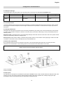
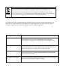
Par Lite Led
VariWhite
instruction manual
manuale di istruzioni
Version 1.0
DIS139
Par Lite Led
VariWhite
Serial number/numero di serie
Date of purchase/data di acquisto
Retailer/fornitore
Address/indirizzo
Suburb/cap/città
Capital city/provincial
State/stato
Tel./fax
Please note in the space provided above the relative service information of the model and the
retailer from whom you purchased your Par Lite Led VariWhite: this information will assist us in
providing spare parts, repairs or in answering any technical enquiries with the utmost speed and
accuracy.
Prendete nota, nello spazio apposite, dei dati relative al modello e al rivenditore del vostro Par Lite
Led VariWhite questi dati ci permetteranno di assistervi con la massima rapidità e precisione.
WARNING: the security of the fixture is granted only if these instructions are strictly followed;
therefore it is absolutely necessary to keep this manual.
ATTENZIONE: la sicurezza dell’apparecchio è garantita solo con l’uso appropriato delle presenti
istruzioni, pertanto è necessario conservarle.
User Manual Version 1.0
edition June, 2011
English
Index
1. PACKAGING AND TRANSPORTATION ...............................................................................................................................................................6
1.1 PACKAGING ........................................................................................................................................................................................................ 6
1.2 TRASPORTATION ...............................................................................................................................................................................................6
2. GENERAL INFORMATION ....................................................................................................................................................................................6
2.1 IMPORTANT SAFETY INFORMATION ................................................................................................................................................................6
2.2 WARRANTY CONDITIONS ..................................................................................................................................................................................6
2.3 EC NORMS ..........................................................................................................................................................................................................6
3. PRODUCT SPECIFICATIONS ...............................................................................................................................................................................7
3.1 TECHNICAL CHARACTERISTICS .......................................................................................................................................................................7
3.2 DIMENSIONS.......................................................................................................................................................................................................7
3.3 UNITS MAIN COMPONENTS ..............................................................................................................................................................................7
4. INSTALLATION .....................................................................................................................................................................................................8
4.1 MECHANICAL INSTALLATION ............................................................................................................................................................................8
4.2 SAFETY CHAIN ...................................................................................................................................................................................................9
4.3 ADJUSTING BEAM DIRECTION ..........................................................................................................................................................................9
4.4 OPENING AND CLOSING UP THE PROJECTOR ............................................................................................................................................. 10
4.5 ADJUSTING THE BEAM ANGLE ....................................................................................................................................................................... 10
5. POWERING UP ...................................................................................................................................................................................................12
5.1 OPERATING VOLTAGE AND FREQUENCY ..................................................................................................................................................... 12
5.2 CONNECTION TO MAINS POWER ................................................................................................................................................................... 12
6. DMX SIGNAL FUNCTIONS .................................................................................................................................................................................13
6.1 CONNECTING DMX SIGNAL.............................................................................................................................................................................13
6.2 POWERING UP.................................................................................................................................................................................................. 13
6.3 DMX ADDRESSING ...........................................................................................................................................................................................14
6.4 DMX CHART ...................................................................................................................................................................................................... 14
7. DIP-SWITCH FUNCTIONS CHART .....................................................................................................................................................................15
8. DR1+ FUNCTION.................................................................................................................................................................................................15
8.1 FUNCTIONAL SETTINGS ( FUNC ) ................................................................................................................................................................... 16
8.2 DISGNOSTICS FUNCTIONS (MEAS) ................................................................................................................................................................17
8.3 SPECIAL FUNCTIONS.......................................................................................................................................................................................18
8.4 ERROR MESSAGES WITH DR1+......................................................................................................................................................................18
9. DIAGNOSTICS AND MAINTENANCE .................................................................................................................................................................19
9.1 DMX PANEL WARNINGS ..................................................................................................................................................................................19
9.2 THERMAL PROTECTION ..................................................................................................................................................................................19
9.3 ORDINARY MAINTENANCE ..............................................................................................................................................................................19
9.4 BLOWN FUSES REPLACEMENT ......................................................................................................................................................................19
9.5 SPARE PARTS .................................................................................................................................................................................................. 19
5
English
Congratulations on having purchased a Coemar product. You have assured yourself a fixture of the highest quality, both in the
componentry and in the technology used. We renew our invitation to you to complete the service information form on the previous
page. This will assist in providing prompt and accurate advice from your Coemar service centre, which you can thoroughly trust
and to which you can submit any requests for service or information. Following the instructions and procedures outlined in this
manual you will ensure the maximum efficiency of this product for years to come.
1. Packaging and transportation
1.1 Packaging
Open the packaging and make sure that no part of the equipment has suffered any damage during the transportation. In case of
damage to the fixture, contact your currier and your supplier immediately by telephone, fax or email, and inform them you will
formally notify them in writing through registered letter.
Packing list
Make sure the packaging contains:
-1 Par Lite Led VariWhite
-this instruction manual
1.2 Trasportation
Par Lite Led VariWhite must be transported exclusively in its original packaging or in an appropriate flight case.
2. General information
2.1 Important safety information
Fire prevention:
1.Never locate the fixture on any flammable surface.
2. Minimum distance from flammable materials: 0,5m.
3. Minimum distance from the closest illuminated surface: 0,5m.
4. Replace any blown or damaged fuse only with those of identical values. Refer to the schematic diagram if there is any doubt.
5. Connect the projector to mains power protected by a thermal magnetic circuit breaker.
Preventing from electric shock:
1. Presence of high voltage inside of the fixture. Insulate the projector from mains supply before opening or performing any function
which involves touching the inside of the fixture, including lamp replacement..
2. For the connection to the mains, adhere strictly to the guidelines outlined in this manual.
3. The level of technology of Par Lite Led VariWhite requires the use of specialised personnel for all service applications; refer all
work to your authorised Coemar service centre.
4. A good earth connection is essential for the proper functioning of the projector. Never connect the fixture if there is no earth
connection.
5. Mains cables must not come into contact with other cables.
6. Do not operate the projector with wet hands or in an area where water is present.
Safety:
1. The projector must always be installed with bolts, clamps, or other fixing devices which are suitably rated to support the weight of
the projector.
2. Always use a secondary safety fixing device with chain or steel wire of a suitable rating to sustain the weight of the unit in case of
failure of the principal fixing point.
3. The external surfaces of the unit, at various points, may reach 80°C. Never handle the unit until at least 10 minutes have elapsed
since the lamp was turned off
4. Never install the fixture in an enclosed area lacking sufficient air flow; the room temperature must not exceed 35°C.
Protection rating of the body against liquids and solids:
The fixture is classified ordinary apparatus, its protection grade against penetration by external agents, solid or liquid is IP20.
2.2 Warranty conditions
1. The fixture is guaranteed for a period of 12 months from the date of purchase against manufacturing or materials defects.
2. The warranty does not extend to damage caused by inappropriate usage, use by inexperienced operators or inadequate
maintenance.
3. The warranty is immediately void if the projector has been tampered or opened by unauthorized personnel.
4. The warranty does not extend to fixture replacement.
5. Both the serial number and the model of the projector are required for any advice or service from your authorised service centre.
2.3 EC Norms
The projector meets all fundamental applicable EC requirements.
6
English
3. Product specifications
3.1 Technical characteristics
Power :
Maximum current:
Power factor:
Light source
:
Minimum room temperature:
Maximum room temperature:
Weight:
90/240 VAC 50/60Hz. Autosensing
0,2A @ 230 VAC
0,5A @ 115VAC
cosϕ = 0,8
36 LED P4
-15°C / -5°F
35°C / 95°F
3.6 Kg / 7.9 Lbs
3.2 Dimensions
3.3 Units main components
The main components of Par Lite Led VariWhite are shown in the diagram below:
Components description:
1. Rear panel
2. Projector body
3. Dip-switch panel
4. Led control pcb
5. Switching power supply
6. Front header
7. Lens group
8. Front frame
7
English
4. Installazion
4.1 Mechanical installation
Par Lite Led VariWhite may be floor mounted or hung from an appropriate structure in any position.
Permanent installation
Use the three holes “A” on the yoke of the fixture for robust, permanent installation.
Mobile installation
If hanging the fixture from a lighting truss or similar we recommend to use appropriate clamps “B” affixed to the yoke in the holes
“A” provided, as shown in the following diagram.
WARNING!
Always ensure that your support structure and fixing (bolts, clamps, etc…)
are rated to support the weight of the fixture.
Never install the fixture in an accessible position to personnel who may ignore or be unaware of the safety directions mentioned in
this manual.
8
English
4.2 Safety chain
When hanging Par Lite Led VariWhite we recommend the use of a safety chain affine to the body and to the suspension device.
The safety chain should be either a metal rope or a metal chain, both suitably for the purpose.
4.3 Adjusting beam direction
Par Lite Led VariWhite can be tilted to adjust the beam output. To perform this adjustment, follow the instruction set out below.
1. Loosen the handle “D” located on the side of the projector, thus allowing the inclination to be changed.
2. Adjust the projector tilt
3. Refasten the handle “D” on the side of the projector.
9
English
4.4 Opening and closing up the projector
The various procedures which follow can only be performed with the projector housing removed.
To gain access to the internal of the projector use a suitable screwdriver to remove the 3 screws “E” which affix the front frame and
remove it.
You should now have complete access to the internal of the projector and proceed to carry out the procedures described below.
ATTENTION !
Remove mains power prior to opening up the projector.
To close up the projector, replace the housing and reaffix the 3 screws previously removed.
4.5 Adjusting the beam angle
Several optional optical groups are available for Par Lite Led VariWhite. They are used to vary the beam dimension and make it
suitable for different lighting applications and specifically: a group of lenses for a large projection angle, a flood reflector and several
filters that can be fitted either internally or externally to the unit.
The standard optical group fitted on the product is composed by a group of lenses that gives 12° beam angle.
Here following, you will find instructions to install different optical groups.
1. Open the unit as shown on paragraph 4.4 Open and close the unit.
2. Remove the 3 screws “G”.
3. Replace the lenses “L” and ensure that the led of “H” disc fit perfectly in the lenses seats.
If you wish to use an optional filter holder (cod. CO9169/1) follow the instructions as per point 4 and 5..
4. After having positioned in seat the lenses group, insert the “M” filter.
5. Lock it with the “P” filter holder.
6. Close the unit.
10
English
To further increase the beam angle, the “R” reflector is available (cod. CO9168) and it must be fitted instead of the lenses group
and filter holder.
To vary the wideness of the beam without opening the unit it’s possible to install an external filter holder “S” (cod. CO9169/1) as
shown in the following image.
The following table details the range of beam angles and diffusion filters available for Par Lite Led VariWhite.
Optical group
Beam Angle
Narrow lenses (standard)
12°
Narrow lenses + Light Frost filter
17°
Narrow lenses + Frost filter
25°
Narrow lenses + Strip Frost filter
Beam shake
Medium lenses (cod 9167)
30°
Medium lenses + Light Frost filter
35°
Medium lenses + Frost filter
45°
Medium lenses + Strip Frost filter
Beam shake
Flood
130°
To shape the beam you can use an external barndoor (cod. CO9164).
11
English
5. Powering up
5.1 Operating voltage and frequency
The unit may operates at voltages ranges from 90 to 250VaC at a frequency of 50 or 60 Hz. It is not needed to effect any setup
procedures:: Par Lite Led VariWhite will automatically adjust its operation to suit any frequency or voltage within this range.
5.2 Connection to mains power
Mains cable characteristics:
The mains cable provided is thermally resistant, complying to the most recent International standards.
Note: in case of cable replacement, similar cable with comparable thermal resistant qualities must be used exclusively (cable 3 X
1,5 ø external 10 mm, rated 300/500V, tested to 2 KV, operating temperature -40°C + 180°C, Coemar cod. CV5311).
Connection to mains power
for connection purposes, ensure you plug is of a suitable rating:
- 230/240VAC
0,2 A constant during normal exercise.
- 208VAC
0,25A constant during normal exercise..
- 100/115VAC
0,5A constant during normal exercise..
Locate the mains cable which exits from the unit and connect as shown below:
WARNING !
• The use of a thermal/magnetic circuit breaker for each fixture is recommended. Strict adherence to regulatory norms is
strongly recommended.
• Par Lite Led VariWhite VariWhite never must be powered through a dimmer as this may damage the internal switching
power supply.
• Prior to connecting the device to mains power, ensure that the power characteristics are within the recommended range
for use with Par Lite Led VariWhite.
• A good earth connection is essential for the correct operation of this device. Never install the unit unless the
yellow/green earth cable is securely connected.
• All cabling and connections should be carried out by qualified personnel.
12
English
6. DMX signal functions
6.1 Connecting DMX signal
Control signal is digital and is transmitted via two pair screened cables, as required by international standards for the transmission
of DMX512. Connection is in serial mode and it will be performed using the XLR3 sockets located on the rear panel of the unit..
Signal connection via the XLR3 connectors
The connection meets international standards; it must be carried out as shown in the picture below.
pin 1= GND
pin 2 = DATA pin 3 = DATA +
If the signal comes from a DMX512 controller with XLR5 connector ( 5 pins) pins 4 and 5 should remain not connected.
WARNING !
Cables and shielding should never come into contact with each other. The pin #1 and the metal housing should never be
connected to the earthing of the unit.
6.2 Powering up
After having correctly followed,the previous operations, it is possible to proceed in powering up the unit. The POWER Led near the
dip-switch panel will turn on.
Turning on the unit with DMX signal connected.
The yellow DMX led will blink to indicate that the DMX512 is correctly received. If it is off, it means that DMX signal is not received (
see chapter 9 Diagnostics and maintenance at the end of this manual ).
13
English
6.3 DMX Addressing
Each Par Lite Led VariWhite uses 4 DMX channels for its control. The address can be set by dip-switch panel 1-256 simply by
adding the values of each dip switch set as ON; for example: to set the unit to DMX address at 9 you should set to ON dip-switches
marked 8 and 1 while to set the unit to DMX address at 12 you should put 4 and 8 switches to on.
6.4 DMX chart
c ha nne l
func tio n
ty p e o f c o ntro l
1
ma s te r d imme r
proportional
2
fine white
a d jus t +10%
step
proportional
step
3
fine white
a d jus t -10%
proportional
step
proportional
step
proportional
step
4
s tro b e
proportional
step
proportional
step
proportional
e ffe c t
p e rc e nta g e
adjust luminous output intensity from 0 to 100%
0
- 255
0%
- 100%
no effect
0
-
0%
- 4%
adjust fine color temperature +10%
from 3200°K to 3500°K
10
- 255
4%
- 100%
no effect
0
-
0%
- 4%
adjust fine color temperature -10%
from 3200°K to 2700°K
10
- 255
4%
- 100%
no effect
0
-
9
0%
- 4%
variable speed strobing effect, from slow to fast
10
-
57
4%
- 22%
stop strobe
58
-
59
23% - 23%
sequenced pulse effect, slow closing, fast opening
(variable speed pulsing, from slow to fast)
60
- 108
24% - 42%
stop strobe
109 - 110
43% - 43%
sequenced pulse effect, fast closing, slow opening
(variable speed pulsing, from slow to fast)
111 - 159
44% - 62%
stop strobe
160 - 161
63% - 63%
random strobe effect with variable speed from slow to fast
162 - 207
64% - 81%
stop strobe
208 - 209
82% - 82%
random strobe effect with variable speed from slow to fast
210 - 255
82% - 100%
Fixture : P a rLite Le d V a riW hite
2700/ 3500°K
T a b le na me : D MX 512 func tio n
T a b le numb e r: 317
D a te : 10/ 06/ 2011
E d itio n: 0
d e c ima l
14
9
9
English
7. Dip-switch functions chart
The following chart summarizes the functions achievable by setting the unit by dip-switch panel.
dip-switc h
DMX
func tion
DR1
func tion
1
dmx channel 1
Id value 1
dip-switc h
func tion
LIGHT ON func tion
dip-switc h general func tions
dip-switch 1
dip-switch 2
dip-switch 4
luminous intensity
on
off
on
off
on
off
on
off
on
on
off
off
on
on
off
off
off
on
on
on
on
luminous intensity 20%
luminous intensity 30%
luminous intensity 40%
luminous intensity 50%
luminous intensity 60%
luminous intensity 80%
luminous intensity 100%
dip-switch 8
dip-switch 16
dip-switch 32
white temperature fine
regolation
off
on
off
on
off
on
off
on
off
off
on
on
off
off
on
on
off
off
off
off
on
on
on
on
2700°K
2900°K
3000°K
3100°K
3200°K
3300°K
3400°K
3500°K
2
dmx channel 2
Id value 2
4
dmx channel 4
Id value 4
8
dmx channel 8
Id value 8
16
dmx channel
16
Id value 16
32
dmx channel
32
Id value 32
64
dmx channel
64
Id value 64
128
dmx channel
128
Id value 128
256
dmx channel
256
Id value 256
DIMMER CURVE
N.F.
N.F.
ON
OFF
Active Xenon dimmer curve. On OFF the dimmer curve is halogen (Thungsten)
TEST
N.F.
N.F.
ON
OFF
Quick test of the sequence of channels.
LIGHT ON
OFF
OFF
ON
Leds are on. Intensity e cromaticy is on 7 levels which are set by a combinations of the dip-switches.
Dip-switches from 1 to 4 for intensity, dip-switches from 8 to 32 for white color temperature.
1 CH
OFF
OFF
ON
OFF
1 CH function is on, only dimmer works.
COLOR
TEMPERATURE
N.F.
N.F.
ON
OFF
ON: Color temperature change with the dimmer like an halogen lamp
OFF: Costant color temperature while dimmer works
DR1
N.F.
N.F.
OFF
To by-pass hardware information and to communicate with DR1. All the other dip-switch functions are
disabled. The DR1 display allows to operate with every ParLite Led (for example to change address
and many other functions).
The dip-switch from 1 to 256 is used to set up ParLite Led ID.
N.F.
OFF
ON
OFF
Dip-switches (from 1 to 256) functions will change depending on Function mode buttons selected
no function
Note 1: the dip-switc h T EST -LIGHT ON-DR1 must be set c orrec tly to av oid func tion c onflic ts.
led
func tion
led off
flashing led
green
power
no power
not required
yellow
DMX state
no DMX
DMX ok
8. DR1+ function
DR1+ device ( cod. CO9709) allows to use and benefit of all capabilities of the unit from remote; by DR1+ it is possible to consult all
the internal menu of Par Lite Led VariWhite, to sed DMX address, to change settings, read the diagnostics and upgrade the
firmware.
In order to set the unit to work in DR1+ mode is strictly required to activate the function by dip-switch panel ( see previous chapter)
and set the ID also by dip-switch panel.
The menu browsing will be emulated on the PC screen on which has been previously installed “DR1+ Lite Interface” software which
is included in the DR1+ device package. To browse the menu use “menu”, “enter”, “+” and”-“ keys visualized on the PC screen in
the same way you are operating on any Coemar product with display.
15
English
8.1 Functional settings ( FUNC )
FUNC
DFSE
SURE
+10%
It restores all settings at default values, in exception of aligning,
address and life hour of the unit.
0 - 255
-10%
0 - 255
STRB
0 - 255
STOR
SURE
It allows to vary the color temperature
shade from 2700°K to 3500°K without
DMX signal.
STORE saves the settings until next turn
on of the unit
TEST
RESE
-enter
DIMM
-XENO
-TUNG
Dimmer mode: it allows to emulate the dimming behavior of a
Tungsten or Xenon lamp’s dimmer.
1CH
-On
-Off
It enables the control of the unit by 1 DMX channel (dimmer).
C.TMP
-On
-Off
It enables the unit to act like an halogen lamp: by varying the dimmer
values, changes also the color temperature.
BOOT
-DMX
-TEST
ENTER and MENU makes to access to adjusting functions.
It sets the turn on of the unit without DMX signal;
-DMX restores the last DMX value received
-TEST restores the TEST value manually set.
16
English
8.2 Disgnostics functions (MEAS)
MEAS
TEMP
Reading of the internal LED temperature of the leds in °C.
D.MIN
Reading of the DMX value received by each channel used by
the unit in the DMX chain.
RATE
Reading of the typical value of the DMX signal called “RATE”
( signal refresh frequency in milliseconds).
ALRM
Reading of the eventual error message.
S.VER
Reading of the software version actually installed on to the unit
ID
HOUR
Setting of the ID number of the unit.
Reading of the led s life: LIFE shows total life of all the led
modules installed on the unit, UNIT shows the whole life of the
unit.
17
English
8.3 Special functions.
By this menu, accessible by keep pressed “menu” and “enter”after the reset for about 10”, it is possible to access to aligning
functions of the leds and to software upgrading functions.
WARNING !
This function is achievable only with DMX signal connected by enabling the
reset while keeping pressed “menu “ and “enter” keys for 10”
Min.1
Adjusting of minimum light intensity of channel1 leds.
Min.2
Adjusting of minimum light intensity of channel 2 leds.
Min.3
Adjusting of minimum light intensity of channel 3 leds.
Max.1
Adjusting of maximum light intensity of channel1 leds.
Max.2
Adjusting of maximum light intensity of channel 2 leds.
Max.3
Adjusting of maximum light intensity of channel 3 leds.
EXIT
It saves the settings and exits from the procedure
UPLD
SURE
It arranges the projector to receive the software from the PC.
DULD
SURE
It arranges the projector to save the software on the PC.
ALIG
8.4 Error messages with DR1+
Message
Description
DTER
DATA error
The initial configuration settings are faulty or have been loaded incorrectly. The projector has loaded its default
configuration. Turn the projector off and on again and if the error persists it means that the EEProm is either
defective or absent; refer to your Coemar service center for the check or replacement of the component.
ADER
DMX ADDRESS error
Teh projector is not receiving all the DMX channels necessary for its operation. Check the DMX address and the
controller’s operation. Note that some controllers may not generate all 512 channels.
18
English
9. Diagnostics and maintenance
9.1 DMX panel warnings
The two leds (green and yellow) sited on the dip-switch panel continuously show Par Lite Led VariWhite.staus.
Led
Verde
Giallo
Function
Led steady on
Led off
Power
Power off
Power off
Signal reception status
DMX signal not correctly
connected.
DMX signal absent
Led blinking
DMX signal correctly
recived.
9.2 Thermal protection
The internal thermal sensor protects the unit from overheating. The thermal sensor limits the current to the leds in order to protect
their integrity if the ambient temperature reaches higher values than those permitted. An eventual loose of output may be due to
this reason.
9.3 Ordinary maintenance
Althought every precautionary has been took to ensure long still efficiency and safety in the use of this equipment we recommend,
in function of the operative conditions in which the unit works ( dusty environment, artificial fog or snow), to periodically make the
following checks:
Mechanical parts: check that the unit is not mechanically damaged; clean often the front screen with a cloth and a specific cleaner
product and if necessary replace the damaged parts.
Electrical parts: check electric cabling, in particular the grounding and the correct insertion of the signal plugs. Check for the lack
of oxidation on electrical contacts, eventually remove it with adequate tools.
9.4 Blown fuses replacement
By an adequate instrument check for the status of the fuses; if they are damaged replace them with ones with equal value,
dimensions and characteristics. In the following picture are shown positions and characteristics of the fuses.
WARNING !
Always remove main power before open the fixture.
Fuse A: 2A F250V
Fuse B: 4A T250V
9.5 Spare parts
All components of the projector are available as spare parts at Coemar Service Centers. Please describe in detail the model of the
projector you own, don’t forget to give the serial number and with the help of the exploded view, identify the right spare part.
Providing the service center with this data you will be better and quickly served.
19
Information on disposal of the equipment
The equipment at the end of its useful life must be disposed of at an appropriate recycling
center for waste electrical and electronic equipment. The treatment and disposal of
environmentally friendly, helps prevent potential negative environmental and health and
promote the reuse and / or recycling of materials making up the equipment. Illegal disposal by
the user includes the application of administrative sanctions provided by law.
Our equipment has been manufactured and assembled by the rules and the essential requirements of the
RoHS directive, so the materials we use and electronic subassemblies that we receive from our suppliers
have been checked and are produced in compliance with the Directive in question.
Reference no.
title
2004/108/EC
Directive of the European Parliament and of the Council of 15 December 2004
on the approximation of the laws of the Member States relating to
Electromagnetic Compatibility and repealing Directive 89/336/EEC (EMC)
2006/95/EC
Directive of the European Parliament and of the Council of 12 December 2006
on the harmonisation of the laws of Member States relating to electrical
equipment designed for use within certain voltage limits (LVD)
2002/95/EC
Directive of the European Parliament and of the Council of 27 January 2003 on
the restriction of the use of certain hazardous substances in electrical and
electronic equipment (RoHS)
2002/96/EC & 2003/108/EC
Directive of the European Parliament and of the Council of 27 January 2003 on
waste electrical and electronic equipments (WEEE)