1
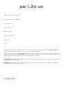
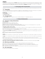
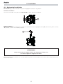
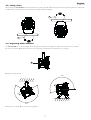
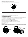
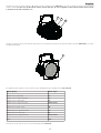
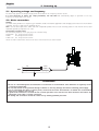
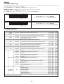
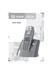
par lite
LED
manuale di istruzioni
instructions manual
Version 1.1
par
Lite LED
numero di serie/serial number
data di acquisto/date of purchase
fornitore/retailer
indirizzo/address
cap/città/suburb
provincia/capital city
stato/state
tel./fax/
Prendete nota, nello spazio apposito, dei dati relativi al modello e al rivenditore del vostro Par Lite LED: questi dati ci permetteranno di assistervi con la massima rapidità e precisione.
Please note in the space provided above the relative service information of the model and the retailer from
whom you purchased your Par Lite LED: this information will assist us in providing spare parts, repairs or in
answering any technical enquiries with the utmost speed and accuracy.
ATTENZIONE: la sicurezza dell’apparecchio è garantita solo con l’uso appropriato delle presenti istruzioni, per-
tanto è necessario conservarle.
WARNING: the security of the fixture is granted only if these instructions are strictly followed; therefore it is
absolutely necessary to keep this manual.
Users Manual Version 1.1
edition November 2005
English
Index
1. Packaging and transportation
Pag. 4
1.1. Packaging
1.2. Transportation
“
“
2. General information
Pag. 4
2.1. Important safety information
2.2. Warranty conditions
2.3. CE Certification
“
“
“
3. Product specifications
“
“
“
4. Installation
5
5
5
Pag. 6
Mechanical installation
Attaching a safety chain
Adjusting beam direction
Opening and closing up the projector
Adjusting the beam angle
“
“
“
“
“
5. Powering up
6
7
7
8
8
Pag. 10
5.1. Operating voltage and frequency
5.2. Mains connection
“
“
6. DMX signal functions
6.1.
6.2.
6.3.
6.4.
4
4
4
Pag. 5
3.1. Technical characteristics
3.2. Dimensions
3.3. Projector components
4.1.
4.2.
4.3.
4.4.
4.5.
4
4
10
10
Pag. 11
Connecting DMX signal
Turning on the projector
DMX addressing
DMX functions
“
“
“
“
11
11
12
12
7. Test function
Pag. 13
8. Light ON function
Pag. 13
9. Auto function
Pag. 14
9.1. Master/Slave mode
9.2. Stand Alone mode
“
“
10. IR function
Pag. 16
10.1. Master/Slave mode IR
10.2. Stand Alone mode IR
“
“
11. DR1 function
11.1.
11.2.
11.3.
11.4.
14
15
16
17
Pag. 17
Functions using DR1 (MODE)
Setting up functionality using DR1 (FUNC)
Diagnostic functions using DR1 (MEAS)
Error messages using DR1
“
“
“
“
18
19
20
20
12. Switch panel signals
Pag. 21
13. Thermal protection
Pag. 21
14. Maintenance
Pag. 21
14.1. Replacing blown fuses
14.2. Periodic maintenance
“
“
21
21
15. Spare parts
Pag. 21
16. Frequently asked questions
Pag. 22
3
English
Congratulations on having purchased a Coemar product. You have assured yourself of a fixture of the highest quality, both in componentry and in the technology used. We renew our invitation to you to complete the service information on the previous page, to expedite any request for service information or spares (in case of problems encountered either during, or subsequent to, installation). This
information will assist in providing prompt and accurate advice from your Coemar service centre..
1. Packaging and transportation
Following the instructions and procedures outlined in this manual will ensure the maximum efficiency of this product for years to come.
1.1. Packaging
Open the packaging and ensure that no part of the equipment has suffered damage in transit. In case of damage to the equipment,
contact your carrier immediately by telephone or fax, following this with formal notification in writing.
Packing list
Ensure the packaging contains:
1 Par Lite LED
1 Instruction manual
1.2. Transportation
The Par Lite LED should be transported in either its original packaging or in an appropriate flight case.
2. General information
2.1. Important safety information
Fire prevention:
1. Never locate the fixture on a flammable surface.
2. Minimum distance from flammable materials: 0.5 m.
3. Minimum distance from the closest illuminable surface: 0,5 m.
4. Replace any blown or damaged fuses only with those of identical values. Refer to the schematic diagram if there is any doubt.
5. Connect the projector to mains power via a thermal magnetic circuit breaker.
Prevention against electric shock:
1. High voltage is present in the internal of the unit. Isolate the projector from mains supply prior to performing any function which
involves touching the internal of the unit.
2. For mains connection, adhere strictly to the guidelines outlined in this manual.
3. The level of technology inherent in the Par Lite LED requires the use of specialised personnel for all service applications; refer all work
to your authorised Coemar service centre.
4. A good earth connection is essential for proper functioning of the projector. Never operate the unit without proper earth connection.
5. The mains cable should not come into contact with other cabling.
6. Never handle the unit with wet hands or in a damp environment.
Safety:
1. The projector should always be installed with bolts, clamps, and other fixings which are suitably rated to support the weight of the
unit.
2. Always use a secondary safety chain of a suitable rating to sustain the weight of the unit in case of the failure of the primary fixing
point..
3. Never install the fixture in an enclosed area lacking sufficient air flow; the ambient temperature should not exceed 35°C.
4. The external surface of the unit, at various points, may exceed 80°C. Never handle the unit until at least 10 minutes have elapsed
since the unit was turned off..
Protection rating of the body against liquids and solids:
1. The fixture is classified ordinary apparatus ; its protection grade against penetration by external agents,solid or liquid, is IP 20
2.2. Warranty conditions
1. The fixture is guaranteed for a period of 12 months against manufacturing faults and faulty materials.
2. Faults due to incorrect operation or operation in an inappropriate manner are not covered by the warranty.
3. The warranty is immediately void if the fixture has been operated or serviced by unqualified or unauthorised personnel.
4. The warranty does not include fixture replacement.
5. The model and serial numbers must be supplied for any warranty claims or advice from our authorised service personnel.
2.3. CE Certification
The fixture meets all requirements for CE certification.
4
English
3. Product specifications
3.1. Technical characteristics
Power:
Nominal current:
Power factor:
Led power:
Minimum ambient temperature:
Maximum ambient temperature:
Weight:
90/240 Vac 50/60Hz Autosensing
0.2A @ 230Vac
0.5A @ 115V
cos ϕ = 0.8
36 Led x 1W
-15°C / 5°F
35°C / 95°F
3.6 Kg / 7.9 lbs
211mm
8.30”
268mm
10.55”
167mm
6.46”
3.2. Dimensions
184mm
7.24”
268mm
10.5”
212mm
8.35”
3.3. Projector components
The principal components of the Par Lite LED are shown in the diagram below.
Descrizione dei componenti
1. Rear panel
2. Projector body
3. Dip-switch panel
4. Led control PCB
5. Switching power supply
6. Head
7. Lens group
8. Front frame
5
English
4. Installation
4.1. Mechanical installation
Par Lite LED may be floor mounted or hung from an appropriate structure in any position.
30mm
1.18”
Permanent installation
Use the three holes “A” on the yoke of the Par Lite LED for robust, permanent installation.
30mm
1.18”
A
Mobile installations
If hanging the fixture from a lighting truss or similar, we recommend the use of appropriate clamps “B”, affixed to the yoke in the holes
“A” provided, as shown in the following diagram.
B
ATTENTION!!
Always ensure that your support structure and fixings (bolts, clamps, etc.)
are rated to support the weight of the fixture.
Never install the fixture in a position in an accessible position to personnel who may ignore or be unaware of the safety directions mentioned in this manual.
6
English
4.2. Safety chain
When hanging the Par Lite LED we recommend the use of a safety chain “C” affixed to the yoke and to the suspension device. The safety chain
should be either a metal wire rope or a metal chain, both suitably rated for the purpose.
C
C
4.3. Adjusting beam direction
The Par Lite LED can be tilted to adjust the beam output. To perform this adjustment, follow the instructions set out below.
1. Loosen the handle “D” located on the side of the projector, thus allowing the inclination to be changed.
D
2. Adjust the projector’s tilt.
200°
240°
3. Refasten the handle “D” on the side of the projector.
7
English
4.4. Opening and closing up the projector
The various procedures which follow can only be performed with the projector housing removed.
To gain access to the internal of the projector use a suitable screwdriver to remove the 3 screws “E” which affix the front frame and
remove it.
E
E
E
You should now have complete access to the internal of the projector and can proceed to carry out the procedures described below.
ATTENTION!!
Remove mains power prior to opening up the projector..
To close up the projector, replace the housing and reaffix the 3 screws previously removed.
4.5. Adjusting the beam angle
Several optional optical groups are available for Par Lite Led. They are used to vary the beam dimension and make it suitable for different lighting applications and specifically: a group of lenses for a larger projection angle, a flood reflector and several filters that can
be fitted either internally or externally to the unit
The standard optical group, fitted on Par Lite Led, is composed by a group of lenses that gives 12° beam angle.
Here following you will find instructions to install different optical groups.
1. Open the unit as shown on paragraph 4.4 Open and close the unit
2. Remove the 3 screws “G”.
3. Replace the lenses “L” and ensure that the led of “H” disc fit perfectly in the lenses seats
If you wish to use an optional filter holder (code CO9169) follow the instructions as per point 4 and 5.
4. After having positioned the lenses group insert the “M” filter
5. Lock it with the “P” filter holder
6. Tighten the 3 “G” fixing screws
7. Close the unit
For the users of the optional IR remote control: ensure that the “N” slot is aligned as per drawing on lenses group and
filter holder with IR sensor is positioned on the side of led disc.
H
L
M
G
8
N
P
English
To further increase the beam angle the “R” flood reflector is available (code CO9168) and it must be fitted instead of the lenses group
and filter holder. For the user of IR remote control: ensure that the “N” slot is aligned on the reflector where the IR sensor
is located on the side of led disc “H”.
H
N
R
To vary the wideness of the beam without opening the unit, it’s possible to install an external filter holder “S” (code CO9169/1), as shown
on following drawing.
S
The following table details the range of beam angle and diffusion filters available for the Par Lite Led.
Optical group
Beam angle
Narrow Lenses (standard)
12°
Narrow Lenses + Light Frost Filter
17°
Narrow Lenses + Frost Filter
25°
Narrow Lenses + Strip Frost Filter
Beam Shake
Medium Lenses (cod. 9167)
30°
Medium Lenses + Light Frost Filter
35°
Medium Lenses + Frost Filter
45°
Medium Lenses + Strip Frost Filter
Beam Shake
Flood
130°
To shape the beam you can use an external barndoor (code CO9164).
9
English
5. Powering up
5.1. Operating voltage and frequency
The fixture may operate at voltages ranging from 90 to 250V AC at a frequency of 50 or 60 Hz.
It is not necessary to effect any setup procedures, Par Lite LED will automatically adjust its operation to suit any
frequency or voltage within this range.
5.2. Mains connection
Cabling
The mains cable provided is a neoprene type HQ7RN-F suitable for outdoor applications and complying to the most recent international
standards: CEI 20-19, UNEL 35364, CENELEC HD 22.
N.B. In case of cable replacement, similar cable with comparable qualities must be used exclusively (cable 3x1.5 ø external 10 mm, rated
450/750V, operating temperature -25° +60°.
Connection to mains power
for connection purposes, ensure you plug is of a suitable rating:
•230/240V 0.2 amps constant current.
•208V
0.25 amps constant current.
•100/115V 0.5 amps constant current.
Locate the mains cable which exits the base of the unit and connect as shown below:
main
live
brown
neutral
blue
ground
yellow/green
ATTENTION!!
• The use of a thermal/magnetic circuit breaker for each fixture is recommended. Strict adherence to regulatory norms
is strongly recommended.
• Par Lite Led should not be powered through a Dimmer as this may damage the internal switching powersupply.
• Prior to connecting the device to mains power, ensure that the mains characteristics are within the recommended
range for use with the Par Lite Led.
• A good earth connection is essential for the correcdt operation of the Par Lite Led. Never install the unit unless the
yellow/gree earth cable is securely connected.
• All cabling and connections should be carried out by suitably qualified personnel.
10
English
6. DMX signal functions
Par Lite LED can operate in three modes:
1. using DMX512 control signal
2. automated “STAND ALONE” or “MASTER/SLAVE” modes (see chapter 9. AUTO function)
3. using an IR remote in either “STAND ALONE” or “MASTER/SLAVE” (see chapter 10. IR function)
6.1. Connecting DMX signal
Control signal is digital and is transmitted via two pair screened cable, as recommended in international standards for the transmission
of DMX512. Connection is serial, utilising the XLR3 sockets located on the rear panel of the Par Lite LED.
Signal connection via the XLR3 connectors
Connection is to international standards. Connection is as indicated below:
pin 1 = GND
pin 2 = data pin 3 = data +
Should your DMX 512 controller output signal via a cannon XLR5 (5 pin), pins 4 and 5 should remain unconnected.
in
out
Controller
Standard
DMX 512
OUT
in
out
3
2
1
Ad altri Par Lite Led
Connect to other Par Lite Led
ATTENTION!!
Ensure that all data conductors are isolated from one another, the screening and the metal housing of the connector.
Pin number 1 and the housing should never be connected to mains power.
6.2. Powering up
After having followed the preceding steps, turn on mains power on to the unit.
The POWER led located near the dip-switch panel will come on.
Turning on power with DMX signal connected.
The yellow DMX led will flash to indicate that DMX 512 is being correctly received. If the yellow led is off, DMX signal is not being
received (see section 16. Frequently asked questions).
11
English
6.3. DMX addressing
Via the dip-switch panel, it is possible to assign a DMX address to the fixture. The address is determined by the sum of the values associated with the dip switches set to the on position.
Each Par Lite LED utilises 6 channels of DMX 512 signal for complete control.
IMPORTANT NOTE: the following points are valid for all the instructions which follow.
1. Setting a dip-switch to the ON position activates its function
2. The DMX address may be altered without the need to turn the Par Lite LED off.
The following are examples only for setting DMX addresses.
ON
2
4
8 16 32 64 128 256
Par Lite LED number 1 Address DMX 001
is obtained by setting dip-switch 1 to the ON position
DR1
1
IR
8 16 32 64 128 256
light on
4
test
2
auto
1
ON
DR1
IR
light on
test
auto
Par Lite LED number 2 Address DMX 007
is obtained by setting dip-switches 1, 2 & 4 to the ON position
6.4. DMX functions
channel
function
type of control
1
master
dimmer
proportional
2
red
2
speed
effect
decimal
percentage
adjust luminous output intensity from 0 to 100%
0
- 255
0% - 100%
proportional
proportional control of the percentage of red colour from 0 to 100%
0
- 255
0% - 100%
proportional
fade speed between colours from fast to slow
(from 1 second to 1 minute)
0
- 255
0% - 100%
Note 1: channel 2 has various functions depending upon the selection made on channel 6
3
green
proportional
proportional control of the percentage of green colour from 0 to 100%
0
- 255
0% - 100%
3
pause
proportional
control of the pause time between colours (steps); the pause time is
adjustable proportionally from 1 second to 3.30 minutes
0
- 255
0% - 100%
- 255
0% - 100%
Note 2: channel 3 has various functions depending upon the selection made on channel 6
4
blue
proportional
proportional control of the percentage of blue colour from 0 to 100%
0
step
proportional
step
no effect
variable speed strobing effect, from slow to fast
stop strobe
sequenced pulse effect, slow closing, fast opening
(variable speed pulsing, from slow to fast)
0 - 9
10 - 57
58 - 59
0% - 4%
4% - 22%
23% - 23%
60 - 108
24% - 42%
stop strobe
sequenced pulse effect, fast closing, slow opening
(variable speed pulsing, from slow to fast)
109 - 110
43% - 43%
111 - 159
44% - 62%
160 - 161
63% - 63%
162 - 207
64% - 81%
proportional
step
5
strobe effect
proportional
step
proportional
step
proportional
6
automated
functions
step
stop strobe
random strobe effect with variable speed from slow to fast and
synchronised colours
stop strobe
random strobe effect with variable speed from slow to fast and
non-synchronised colours
208 - 209
82% - 82%
210 - 255
82% - 100%
no effect
automated program 1
automated program 2
automated program 3
automated program 4
random program repeat
repeat all programs in sequence
0
10
51
92
133
174
215
0%
4%
20%
36%
52%
68%
84%
Note 3: pause and speed settings are added
12
-
9
50
91
132
173
214
255
-
4%
20%
36%
52%
68%
84%
100%
English
7. Test function
With the dip-switch set to the ON position, Par Lite LED will test each individual channel without the need for a DMX controller to
be connected.
For example:
ON
set the dip-switch to ON on the Par Lite LED.
The fixture will perform a quick sequential channel test
DR1
IR
8 16 32 64 128 256
light on
4
test
2
auto
1
8. Light ON Function
Via this function the leds of the Par Lite LED may be set to always on at a predetermined intensity.
When set to ON the dip-switch, illumination level and colour can be set by a combination of settings as shown in the table below.
dip-switch 1
dip-switch 2
dip-switch 4
Red
on
off
on
off
on
off
on
off
on
on
off
off
on
on
off
off
off
on
on
on
on
illumination level 20%
illumination level 30%
illumination level 40%
illumination level 50%
illumination level 60%
illumination level 80%
illumination level 100%
dip-switch 8
dip-switch 16
dip-switch 32
Green
on
off
on
off
on
off
on
off
on
on
off
off
on
on
off
off
off
on
on
on
on
illumination level 20%
illumination level 30%
illumination level 40%
illumination level 50%
illumination level 60%
illumination level 80%
illumination level 100%
dip-switch 64
dip-switch 128
dip-switch 256
Blue
on
off
on
off
on
off
on
off
on
on
off
off
on
on
off
off
off
on
on
on
on
illumination level 20%
illumination level 30%
illumination level 40%
illumination level 50%
illumination level 60%
illumination level 80%
illumination level 100%
Other examples of possible setting combinations are shown below.
ON
DR1
IR
8 16 32 64 128 256
light on
4
test
2
auto
1
LIGHT ON dip-switch set to ON
RED at 20% (dip-switch 1 set to ON)
GREEN at 30% (dip-switch 16 set to ON)
BLUE at 50% (dip-switch 256 set to ON)
ON
DR1
IR
8 16 32 64 128 256
light on
4
test
2
auto
1
LIGHT ON dip-switch set to ON
RED off
GREEN off
BLUE at 100% (dip-switches 64, 128, 256 set to ON)
ATTENTION!!
Setting the Light ON dip-switch to active inhibits control via DMX signal.
The three colour dip-switches set to the OFF position turn off the colour.
13
English
9. Auto function
This function can be used to determine the operating mode of the projector (either STAND ALONE or MASTER/SLAVE), make program selections or alter the crossfade times. Setting this function to on inhibits control via DMX signal.
9.1. MASTER/SLAVE mode
In MASTER/SLAVE mode, it is possible to control, via a projector set as MASTER, a series of Par Lite LED units set to act as SLAVE fixtures. The table below displays the settings required for fixtures to be connected in this manner.
MASTER
ON
out
DR1
IR
8 16 32 64 128 256
light on
4
test
2
auto
1
Par Lite LED set as MASTER
running program 1
To configure a Par Lite LED as MASTER is simply a matter of setting the Auto dip-switch
to the ON position and selecting a program for it to follow by making a selection from the
following dip-switches: 1-2-4-8-256. There are 4 programs which can be selected.
- dip switches 1-2-4-8 select programs 1, 2, 3, and 4 respectively.
- dip-switch 256 runs all four programs sequentially
ATTENTION!!
It is only possible to select one program at a time.
SLAVE
ON
in
DR1
8 16 32 64 128 256
IR
4
light on
2
test
1
auto
out
Par Lite LED
set to SLAVE
To configure a Par Lite LED as SLAVE is simply a matter of setting the Auto dip-switch to
the ON. All other dip-switches should be set to OFF.
Ad altri Par Lite Led SLAVE
Connect to other Par Lite Led SLAVE
14
English
After having selected the program you wish to run, dip-switches 16 and 32 may be used to set the wait time for each scene in the selected program. In this manner, programs can be made to run faster or slower according to your requirements. The following table outlines the
dip-switch settings and their associated wait times.
time (wait time)
dip-switch 16
dip-switch 32
off
off
hold time
on
off
hold time 10 second
off
on
on
on
hold time 30 second
hold time 1 minute
3 second
Via dip-switches 64 and 128 it is possible to set the fade times for each scene in the selected program. The following table outlines the dipswitch settings and their associated fade times.
speed (fade time)
dip-switch 64
dip-switch 128
off
off
crossfade time
on
off
crossfade time 10 second
3 second
off
on
on
on
crossfade time 30 second
crossfade time 1 minute
The timing for each scene in a program is therefore a sum of the crossfade and hold times as set via these dip-switches
The following table gives an example of a possible setting.
Par Lite LED set as a MASTER running program 3
hold time 30 sec. crossfade time 10 sec.
Set the AUTO and 4 dipswitches to ON will select the fixture as MASTER
running program 3.
Setting dip-switch 16 to OFF and 32 to ON will set a hold time of 30 sec.
Dip-switch 64 to ON and 128 to OFF will set a crossfade time of 10 sec.
ON
DR1
IR
8 16 32 64 128 256
led on
4
test
2
auto
1
ATTENTION!!
When the AUTO function is selected DMX signal reception is disabled to avoid system conflicts.
9.2. STAND ALONE mode
In STAND ALONE mode the projector operates independently with no need for DMX signal. It is possible to select the program which
the projector runs and to alter the hold and crossfade times.
STAND ALONE
ON
DR1
IR
8 16 32 64 128 256
light on
4
test
2
auto
1
Par Lite LED set as STAND ALONE
running program 1
To configure the Par Lite LED as STAND ALONE simply set dip-switch Auto to the ON
position and select the program you wish to run and the hold and crossfade times to follow, as described in the previous section.
15
English
10. IR function
This function allows for control via an optional infrared controller and receiver (infrared receiver cod. CO9163, controller cod.FO9281).
Via this function, it is possible to select the operating mode (STAND ALONE or MASTER/SLAVE). The use of this function disables the
use of DMX signal.
10.1. IR MASTER/SLAVE mode
In MASTER/SLAVE mode it is possible to control a fixture set as MASTER, and other Par Lite LED configured as SLAVES. The following
diagram outlines the necessary settings for this configuration.
MASTER IR
ON
out
DR1
IR
8 16 32 64 128 256
light on
4
test
2
auto
1
Par Lite LED set as
MASTER IR
To configure a Par Lite LED as MASTER set the IR and Auto dip-switches to ON.
SLAVE IR
ON
in
DR1
8 16 32 64 128 256
IR
4
light on
2
test
1
auto
out
Par Lite LED set as
SLAVE group 2
To configure a Par Lite LED as a SLAVE set the IR dip-switch to ON and set to ON the
dip-switch corresponding the the desired group. It is possible to subdivide the units set as
SLAVE into four groups which can be controlled independently. The following diagram outlines the necessary settings for this configuration.
Group 1 - Dip-switch 1
Group 2 - Dip-switch 2
Group 3 - Dip-switch 4
Group 4 - Dip-switch 8
ATTENTION!!
The SLAVE unis of group 1 behave as the MASTER units.
SLAVE IR
ON
in
out
DR1
IR
8 16 32 64 128 256
light on
4
test
2
auto
1
Par Lite LED set as
SLAVE group 3
To configure a Par Lite LED as SLAVE group 3 set the IR dip-switch to ON. Select the
group by setting the ON dip-switch to 4.
Ad altri Par Lite Led SLAVE
Connect to other Par Lite Led SLAVE
ATTENTION!!
To control a Panorama Led RGB SLAVE unit, the controller should be pointed
at its corresponding group’s MASTER fixture.
16
English
10.2. IR STAND ALONE mode
In STAND ALONE mode the projector operates independently of any DMX control signal. All inputs are via the remote control.
STAND ALONE IR
ON
DR1
IR
8 16 32 64 128 256
light on
4
test
2
auto
1
Par Lite LED set to
STAND ALONE IR
To set the Par Lite LED to STAND ALONE mode, set the IR dip-switch to ON.
11. DR1 function
This function allows for the transmission of bidirectional data with the DR1 (cod. CO9703). Via the DR1 (display remote) it is possible
to remotely access, view and alter all the fixture’s parameters and settings.
The DR1 remote display unit allows the user to:
Monitor:
1)
2)
3)
4)
5)
6)
7)
8)
the current Software Version loaded
temperature
led operating life
projector operating life
presence and characteristics of incoming DMX 512
error messages
ID code
alarms
Edit and set:
1) DMX address
2) force leds on
3) function mode
To initiate communications with the Par Lite LED the DR1 must be installed into the DMX signal chain between the fixture and the
controller following the instructions located internally on the unit.
The DR1 dip-switch must be set to the ON position; from this point on, dip-switches 1 to 128 take on the task of assigning an identifying value (ID) to the fixture. They no longer set the fixture’s DMX address, which is done by the DR1. The maximum number of
unique IDs available in the DR1system is 250; dip-switch 256 has no functionality.
An example of a possible configuration is shown below:
ON
DR1
IR
8 16 32 64 128 256
light on
4
test
2
auto
1
Par Lite LED set to ID 13 and DR1 active
configured by setting dip-switch DR1 to ON
and dip-switches 1, 4 and 8 to ON
17
English
11.1. Function modes using DR1 (MODE)
Using the inbuilt functionality of the Par Lite LED via the DR1, it is possible to alter the function mode of the fixture. The following diagram illustrates the menu navigation system of the DR1 in MODE.
AOO1
☞
menu
MODE
☞
+o--
FUNC
☞
+o--
M EA S
☞
enter
☞ D M X DMX function
DMX function mode
☞
AOO1
☞ --M A -- master function
Master unit
☞
PR G.1
+o--
+o--
enter
enter
Example
program 1
☞
enter
PR
O G program
To select the number of
program to run
☞
☞
☞
enter
+o--
☞
+o--
+o--
☞
SPEE
speed
Memories running time (sec)
enter
PRG4
To program 4
P ALL
All programs
0.1
to
☞
0060
☞
☞
0.1
+o--
☞
PRG1
From program 1
☞
☞
☞
enter
enter
enter
☞
☞
enter
enter
+o--
WWaiting
A IT time
waiting time
among
memories (sec)
enter
+o--
☞ --SL-- slave function
Slave unit
☞
☞ --I R -- Infrared control function
To activate the infrared control function
☞
+o--
+o--
enter
enter
☞
+o--
--SL-IR .SA
☞
IR .M A
☞
I R G1
☞
IR G2
☞
I R G3
☞
IR G4
☞
Stand alone
unit
enter
enter
Master unit
☞
+o--
☞
+o--
☞
+o--
☞
+o--
Slave unit
group 1
Slave unit
group 2
Slave unit
group 3
Slave unit
group 4
18
enter
enter
enter
enter
to
0240
☞
☞
enter
enter
English
11.2. Setting up functionality via DR1 (FUNC)
Using the inbuilt functionality of the Par Lite LED via the DR1, it is possible to alter the function settings of the fixture. The following
diagram illustrates the menu navigation system of the DR1 in FUNC.
AOO1
☞
menu
MODE
☞
+o--
FUNC
☞
+o--
M EA S
☞
enter
☞ D F S E default functions setting
To set all the functions at the original values,
+o--
☞
SU R E ☞
enter
enter
but for DMX address and for working time.
☞ TEST test
Function test
+o--
☞
☞
enter
+o--
☞
+o--
enter
0020
GR EE
☞
☞
es.
0127 ☞
0020
☞
☞
enter
es.
0127 ☞
B LU
☞
0020
☞
es.
0127 ☞
ST R B
☞
0020
☞
es.
0127 ☞
ST O R
☞
SU R E
☞
SU R E
☞
R ED
Test red channel
Test green channel
enter
Test blu channel
☞
+o--
enter
Test strobo
☞
+o--
enter
T o record the scene of the unit.
If DMX signal is not applied,
the recorder setting will appear
at the end of reset operation
when the unit is switched on.
☞ UPLD Upload
Software update
+o--
☞
enter
enter
0000
Upload c ount er
UPLOAD function
Using this function it is possible to upload software to the Par Lite LED using a DR1 and a PC.
For further information, consult the DR1 manual.
19
+o--
+o--
+o--
+o--
enter
enter
enter
enter
enter
English
11.3. Diagnostic functions using DR1 (MEAS)
Using MEAS mode, it is possible to carry out several digital parameters checks and autodiagnostics. The following diagram illustrates
the menu navigation system of the DR1 in MEAS.
AOO1
☞
menu
MODE
☞ F U NC
+o--
☞ MEAS
+o--
☞
enter
☞ T EMP temperature
Misure the led housing internal
☞
☞ DMIN DMX value on each channel
Reading of DMX value(0/255), received by
☞
+o--
enter
+o--
each of the 6 channels on DMX512 line.
58C
Temperature
measurement
temperature in °C
enter
☞
+o--
CH01
☞
CH06
☞
From channel 1
enter
enter
To channel 6
☞ RATE DMX rate
Reading of DMX512 signal value
+o--
☞
enter
10
DMX value reading
255
DMX value reading
24
Val u e r e a d i n g
☞
+o--
NDMX
No DMX signal
☞ ALRM alarm
☞
Reading of warning message sequences (errors)
+o--
enter
shown after reset operation .
☞
+o--
☞ S.VER software
Reading fo softwa re release code
☞
☞ ID ID number setting
To set the unit’s ID number from 0
☞
+o--
+o--
enter
NO.AL
No alarm
MAER
Warning messages
02,01
Software release code
enter
1- - 250
N umeric value
(no ID) to 250.
☞ HOUR working time
Working time (in hour)
+o--
☞
☞
enter
+o--
LIF
E
L ed life
UNIT
P rojector life
☞
☞
enter
enter
10
Value reading
1230
Value reading
11.4. Error messages using DR1
MESSAGE CODE
DESCRIPTION
DTER
DATA Error
The initial configuration settings are fautly or have been loaded incorrectly. The projector has loaded its default
configuration. Turn the projector off and on again and if the error persists the EEPROM is either defective or
absent; refer to your Coemar service centre for a replacement component.
ADER
DMX ADDRESS Error
The projector is not receiving all the DMX channels necessary for its operation. Check the DMX address and the
control console operation. Note that some controllers may not generate all 512 channels of signal.
MAER
MASTER MODE Error
This message indicates that the user has attempted to set the unit to MASTER mode whilst DMX signal is still
being received. Detach any DMX control signal or remove MASTER mode settings.
20
English
12. Switch panel signal
The two leds on the dip-switch panel indicate the functionality of the Par Lite LED.
Led
Function
Led on
Led off
Led flashing
Green
Power
Present
Absent
Undefined
Yellow
DMX state
DMX poorly
connected
No DMX signal
DMX OK
13. Thermal protection
A thermal sensor in the body of the Par Lite LED protects the fixture against overheating. The sensor operates by removing power to
the leds should the operating temperature exceed the factory preset.
14. Maintenance
Whilst every possible precaution has been taken to ensure the trouble-free operation of your Par Lite LED, the following periodic maintenance is highly recommended. We recommend that the voltage to the unit be removed prior to any maintenance procedure taking
place.
ATTENTION!!
Always remove mains power prior to opening up the fixture!
14.1. Fuse replacement
Use a multimeter to check the fuse, replacing any faulty or damaged fuses with ones of equal value, dimensions and characteristics.
The following diagram indicates the positioning and characteristics of the protection fuses in the fixture.
Fuse A: 2A F 250V
Fuse B: 4A T 250V
14.2. Periodic maintenance
Mechanicals
Check that the units is not mechanically damaged. Regularly clean the glass by using a soft cloth with a specific cleaning liquid and, if
necessary, replace the damaged parts.
Electrical components
Check all electrical components for correct earthing, oxidation and proper attachment of all connectors, cleaning and refastening if necessary.
15. Spare parts
All the components of the Par Lite LED are available as spare parts from your Coemar service centre.
Accurate description of the fixture, model number, and type will assist us in providing for your requirements in an efficient and effective
manner.
21
English
16. Frequently asked questions
The diagram below indicates some possible problems and solutions if they should occur.
Problem
Par Lite LED won’t turn on.
Possible solution
Mains power is not available to the Par Lite LED:
- Check that the green Led is on, if so check the incoming voltage to the
Par Lite LED.
- Check the main pcb fuse and that of the switching powersupply.
Par Lite LED doesn’t respond to DMX signal
Incoming DMX may not be being received by the Par Lite LED:
- check that the led indicating DMX input is flashing. If not, check the
DMX console’s output and any cabling for continuity.
- Check the dip-switch panel to ensure that no functions are selected
which inhibit DMX control.
- Par Lite LED may be incorrectly addressed. Check the DMX addressing.
The Par Lite LED is set to auto but is not running any pro- In addtion to setting the AUTO dip-switch to on, it is necessary to also
grams
select a program number (see section 9. AUTO function).
- Multiple programs have been selected - only one program at a time
may be selected.
- Check that amongst the interconnected fixtures, only one has bee set
to Master.
- Ensure that there is no incoming DMX signal (this may cause a conflict in signals).
22
English
Coemar s.p.a.
via Inghilterra 2/A - 46042 Castel Goffredo (Mantova) Italy
ph. +39 0376/77521 - fax +39 0376/780657
[email protected]
Coemar si riserva il diritto di apportare modifiche senza preavviso.
Coemar reserves the right to effect modifications without notification