1
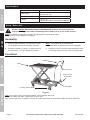
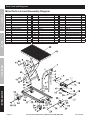
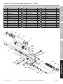
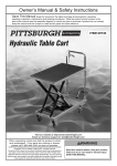
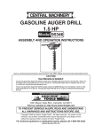
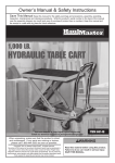
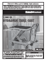
Table of Contents
SAFETY
Safety.......................................................... 3
Specifications.............................................. 4
Setup........................................................... 4
Operation..................................................... 5
Maintenance................................................ 7
Parts Lists and Diagrams............................ 8
Warranty..................................................... 12
SETUP
WARNING SYMBOLS AND DEFINITIONS
This is the safety alert symbol. It is used to alert you to potential personal injury hazards.
Obey all safety messages that follow this symbol to avoid possible injury or death.
Indicates a hazardous situation which, if not avoided,
will result in death or serious injury.
Indicates a hazardous situation which, if not avoided,
could result in death or serious injury.
Indicates a hazardous situation which, if not avoided,
could result in minor or moderate injury.
OPERATION
Addresses practices not related to personal injury.
MAINTENANCE
Page 2
For technical questions, please call 1-800-444-3353.
Item 60438
IMPORTANT SAFETY INFORMATION
2. Do not exceed listed weight capacity.
Be aware of dynamic loading! Sudden
load movement may briefly create excess
load causing product failure.
3. Lock Casters when unattended.
4. Be aware of pinch points. Keep hands and feet clear
of the lifting mechanism during operation.
The Scissor Arm Assembly can cause serious injury
when opening or closing. Do not allow anyone
near the Scissor Arm Assembly during operation.
5. Use only on a flat, stable, hard surface.
6. Do not make any alterations to this product.
7. Wear ANSI-approved safety goggles and
heavy-duty work gloves during use.
8. Keep clear of load while lifting and lowering.
9. Lower load slowly.
10. Inspect before every use; do not use
if parts are loose or damaged.
11. The brass components of this product contain lead,
a chemical known to the State of California to cause
cancer, birth defects (or other reproductive harm).
(California Health & Safety code § 25249.5, et seq.)
12. Before first use, check hydraulic fluid level and fill
to the top of the fill port as described on page 5.
Place the Table Assembly on a flat surface which
is well lighted and safe for assembly operation..
Thoroughly test the Lift Table for proper operation.
13. Maintain labels and nameplates on the tool.
These carry important safety information.
If unreadable or missing, contact
Harbor Freight Tools for a replacement.
14. This product is not a toy.
Keep it out of reach of children.
SETUP
1. Study, understand, and follow all instructions
before operating this device.
SAFETY
Hydraulic Cart Safety Warnings
15. Do not use for aircraft purposes.
16. The warnings, precautions, and instructions
discussed in this instruction manual cannot
cover all possible conditions and situations
that may occur. It must be understood by the
operator that common sense and caution are
factors which cannot be built into this product,
but must be supplied by the operator.
MAINTENANCE
OPERATION
SAVE THESE INSTRUCTIONS.
Item 60438
For technical questions, please call 1-800-444-3353.
Page 3
Specifications
SAFETY
Lift Capacity
1,000 lb.
Table Height
Minimum: 11"
Maximum: 34-1/2"
Table Dimensions
32" L x 20" W
Casters
5" D x 2" W,
(2 swivel with brakes, 2 fixed without brakes)
Setup - Before Use:
Read the ENTIRE IMPORTANT SAFETY INFORMATION section at the beginning of this
manual including all text under subheadings therein before set up or use of this product.
Note: For additional information regarding the parts listed in the following pages,
refer to Parts Lists and Diagrams on page 8.
SETUP
Assembly
1. Place the Table Assembly on a flat surface which
is well lighted and safe for assembly operation.
Note: The Handle may be released and
folded back down by pressing down the Locking Bar.
2. Unfold the Handle by pulling it up and back into a
vertical position. Lock the Handle into position.
3. Install the Pump Lever/Foot Pedal assembly into the
Connecting Rod and secure in place using the Bolt.
Functions
Handle
OPERATION
Table
Control Lever
Pump Lever/
Foot Pedal
Locking Bar
Locking Swivel Caster
MAINTENANCE
Figure A
Note: The Control Lever controls the operation of the Hydraulic Ram unit.
To lower the Ram and Table, squeeze the Control Lever.
When the Control Lever is released, the Ram and Table movement will stop and the table will remain stationary.
Page 4
For technical questions, please call 1-800-444-3353.
Item 60438
Operating Instructions
Read the ENTIRE IMPORTANT SAFETY INFORMATION section at the beginning of this
manual including all text under subheadings therein before set up or use of this product.
Bleeding the Hydraulic Ram
1. Remove any load from the Table.
Note: Before using this tool, the hydraulic ram
must be purged of air (called bleeding).
2. Release the Control Lever,
then repeatedly pump the Foot Pedal.
Filler Bolt
SAFETY
Tool Set Up
3. When the table has been raised, remove the
Filler Bolt from the Housing. Use a rag to catch
any fluid leaks. Keeping hands and tools clear,
squeeze the Control Lever while pumping the
Foot Pedal several times rapidly to lower the Table.
5. Add good quality hydraulic fluid into the opening in
the Housing where the Filler Bolt has been removed.
Fill until the Housing will hold no more fluid.
Housing
Figure B
SETUP
4. Release the Control Lever, and pump
more slowly to raise the Table to its full height.
6. Replace the Filler Bolt and its Seal Washer into
the Housing, tighten, but do not overtighten
to avoid damaging the Washer.
Workpiece and Work Area Set Up
2. Use the Table on a flat, hard, level surface that
is free of debris. Sweep area clean if needed.
MAINTENANCE
1. Designate a work area that is clean and well‑lit.
The work area must not allow access by children
or pets to prevent distraction and injury.
OPERATION
7. Check the condition of the Hydraulic Lift Table before
use. Raise and lower it several times before adding
any load. Be sure that all controls work properly.
Item 60438
For technical questions, please call 1-800-444-3353.
Page 5
General Operating Instructions
SAFETY
1. Unfold the Handle by lifting it up to a
vertical position until it locks in place.
5. Before raising the workpiece, lock
the Locking Swivel Casters.
2. Before placing anything on the cart, lock the
back two casters. The Locking Swivel Casters
can be locked by pressing the lever down into
the locked position with your foot. Test the cart
operation using the Foot Pedal and Control
Lever. Make sure the Table raises and lowers
properly before adding weight to the Table.
6. To raise the Table, ensure that the Control Lever
is in the released position. Press repeatedly
on the Foot Pedal to raise the table.
3. Observing safe lifting procedures,
move the workpiece onto the cart.
If necessary, secure the item onto the cart using
tie-downs or chocks to keep it stable while moving.
4. Release the Locking Swivel Casters by
moving the levers to the unlock position.
Move the workpiece to the desired location.
7. To lower the Table squeeze the Control Lever.
The Table has a 2-speed valve.
Squeeze the Lever halfway for slowly lowering a load.
Squeeze it fully for quickly lowering
the Table when empty.
8. To prevent accidents, when finished using
the cart, move the cart to a safe location,
lock the Locking Swivel Casters, lower the
Table as far as it will go. Clean, then store
the cart indoors out of children’s reach.
SETUP
OPERATION
MAINTENANCE
Page 6
For technical questions, please call 1-800-444-3353.
Item 60438
Maintenance and Servicing
SAFETY
Procedures not specifically explained in this manual must
be performed only by a qualified technician.
TO PREVENT SERIOUS INJURY:
Remove load from Lift Table before service. Lower table when possible before service.
TO PREVENT SERIOUS INJURY FROM TOOL FAILURE:
Do not use damaged equipment. If abnormal noise or vibration
occurs, have the problem corrected before further use.
2. For convenient storage, the handle can be
folded down. To do this, press down on the
Locking Bar, then press down on the Handle.
Note: The Table must be completely lowered
before folding down the Handle.
3. For best service, keep your Hydraulic
Cart clean and in good condition.
6. Do not overload this cart, as that may cause damage
to the seals. If the Table will not raise, or slowly
lowers, the cause may be damaged seals or low
hydraulic oil level. To fix this condition, first try the
purging technique discussed on page 5 of this
booklet. If that doesn’t work, take the Hydraulic
Table Cart to a qualified technician for repair.
7. Occasionally check the condition of the wheels.
They should be kept free of grease and oil, which
may damage the rubber tires. Occasionally add
grease to the grease fittings on each wheel.
8. AFTER USE, wipe external surfaces
of the tool with clean cloth.
MAINTENANCE
4. Store your Hydraulic cart in a location
where it is protected from moisture, dirt
and corrosive atmosphere. Protect it from
being damaged from other items being
moved in and out of its storage area.
5. Occasionally apply light grease to the hinge
points of the Scissor Arm Assembly and
other pivot points of the assembly. Wipe off
excess grease, as this will attract dirt.
OPERATION
1. BEFORE EACH USE, inspect the general condition
of the tool. Check for loose hardware, misalignment
or binding of moving parts, cracked or broken
parts, damaged electrical wiring, and any other
condition that may affect its safe operation.
SETUP
Cleaning, Maintenance, and Lubrication
Item 60438
For technical questions, please call 1-800-444-3353.
Page 7
Parts Lists and Diagrams
Main Parts List and Assembly Diagram
SAFETY
Part
SETUP
1
2
3
4
5
6
7
8
9
10
11
12
13
14
15
16
Description
Handle
Roll Pin
Control Lever
Hex Nut
Bolt
Jacket
Pull Rod
Retaining Ring
Pin
Power Unit
Pin
Retaining Ring
Bushing
Bushing
Cushion
Pump Lever
Qty
1
1
1
13
1
1
1
6
1
1
1
2
2
1
1
1
Part
17
18
19
20
21
22
23
24
25
26
27
28
29
30
31
32
Description
Cotter Pin
Pin
Connecting Rod
Bolt
Foot Pedal
Grip Seat
Cotter Pin
Washer
Handle Lock Pivot
Spring
Pin
Locking Bar
Washer
Spring Washer
Locking Swivel Caster
Base
Qty
1
1
1
13
1
2
6
16
2
2
4
1
2
12
2
1
Part
33
34
35
36
37
38
39
40
41
42
43
44
45
46
47
Description
Lock Nut
Wheel
Bushing
Hex Bolt
Bearing
Washer
Roller
Washer
Pin
Bushing
Scissor Arm Assembly
Bushing
Roller
Protective Mat
Table
Qty
2
2
2
2
4
4
2
4
4
2
1
2
2
1
1
OPERATION
MAINTENANCE
Page 8
For technical questions, please call 1-800-444-3353.
Item 60438
Parts List and Assembly Diagram A – Ram
Description
Qty
Dust Ring
O-ring
Top Nut
Sealing Gasket
Filler Bolt
Housing
T-ring
Cylinder
Copper Washer
Ram
O-ring
Piston
O-ring Retainer
O-ring
Washer
Retaining Ring
3a
Part
1
1
1
1
1
1
1
1
1
1
1
1
1
1
1
1
4a
17a
18a
19a
20a
21a
22a
23a
24a
25a
26a
27a
28a
29a
30a
31a
32a
Description
Qty
Base
Spring
Release Valve
Seal Washer
Axle Sleeve
O-ring
Screw
Nut
Cotter Pin
Pin
Washer
Bolt
Seal Washer
Pump Cylinder
U-cup
Dust Ring
1
1
1
2
1
2
1
3
2
1
2
1
1
1
1
1
Part
33a
34a
35a
36a
37a
38a
39a
40a
41a
42a
43a
44a
45a
46a
47a
48a
Description
Pump Piston
Pin
Linkage
Spring Cap
Spring
Bolt
Plug
Spring
Pumping Valve Spindle
Pumping Valve Seat
Steel Ball
Steel Ball
Ball Seat
Spring
O-ring
Adjusting Bolt
Qty
1
1
2
1
1
1
1
1
1
1
1
1
1
1
1
1
5a
1a
SAFETY
1a
2a
3a
4a
5a
6a
7a
8a
9a
10a
11a
12a
13a
14a
15a
16a
SETUP
Part
6a
2a
7a
8a
OPERATION
48a
47a
46a
9a
45a
44a
42a
11a
12a
21a
22a
13a
20a
14a
15a 16a
19a
18a
43a
40a
41a
20a
38a
17a
25a
28a
27a
38a
37a
36a
24a
23a
25a
24a
26a
24a
29a
30a
31a
32a
Item 60438
33a
For technical questions, please call 1-800-444-3353.
34a
35a
Page 9
MAINTENANCE
10a
PLEASE READ THE FOLLOWING CAREFULLY
THE MANUFACTURER AND/OR DISTRIBUTOR HAS PROVIDED THE PARTS LIST AND ASSEMBLY DIAGRAM
IN THIS MANUAL AS A REFERENCE TOOL ONLY. NEITHER THE MANUFACTURER OR DISTRIBUTOR
MAKES ANY REPRESENTATION OR WARRANTY OF ANY KIND TO THE BUYER THAT HE OR SHE IS
QUALIFIED TO MAKE ANY REPAIRS TO THE PRODUCT, OR THAT HE OR SHE IS QUALIFIED TO REPLACE
ANY PARTS OF THE PRODUCT. IN FACT, THE MANUFACTURER AND/OR DISTRIBUTOR EXPRESSLY
STATES THAT ALL REPAIRS AND PARTS REPLACEMENTS SHOULD BE UNDERTAKEN BY CERTIFIED AND
LICENSED TECHNICIANS, AND NOT BY THE BUYER. THE BUYER ASSUMES ALL RISK AND LIABILITY
ARISING OUT OF HIS OR HER REPAIRS TO THE ORIGINAL PRODUCT OR REPLACEMENT PARTS
THERETO, OR ARISING OUT OF HIS OR HER INSTALLATION OF REPLACEMENT PARTS THERETO.
Page 10
For technical questions, please call 1-800-444-3353.
Item 60438
Record Product’s Serial Number Here:
Note: If product has no serial number, record month and year of purchase instead.
Note: Some parts are listed and shown for illustration purposes only,
and are not available individually as replacement parts.
Item 60438
For technical questions, please call 1-800-444-3353.
Page 11
Limited 90 Day Warranty
Harbor Freight Tools Co. makes every effort to assure that its products meet high quality and durability standards,
and warrants to the original purchaser that this product is free from defects in materials and workmanship for the
period of 90 days from the date of purchase. This warranty does not apply to damage due directly or indirectly,
to misuse, abuse, negligence or accidents, repairs or alterations outside our facilities, criminal activity, improper
installation, normal wear and tear, or to lack of maintenance. We shall in no event be liable for death, injuries
to persons or property, or for incidental, contingent, special or consequential damages arising from the use of
our product. Some states do not allow the exclusion or limitation of incidental or consequential damages, so the
above limitation of exclusion may not apply to you. THIS WARRANTY IS EXPRESSLY IN LIEU OF ALL OTHER
WARRANTIES, EXPRESS OR IMPLIED, INCLUDING THE WARRANTIES OF MERCHANTABILITY AND FITNESS.
To take advantage of this warranty, the product or part must be returned to us with transportation charges
prepaid. Proof of purchase date and an explanation of the complaint must accompany the merchandise.
If our inspection verifies the defect, we will either repair or replace the product at our election or we may
elect to refund the purchase price if we cannot readily and quickly provide you with a replacement. We will
return repaired products at our expense, but if we determine there is no defect, or that the defect resulted
from causes not within the scope of our warranty, then you must bear the cost of returning the product.
This warranty gives you specific legal rights and you may also have other rights which vary from state to state.
3491 Mission Oaks Blvd. • PO Box 6009 • Camarillo, CA 93011 • (800) 444-3353