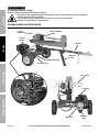
1
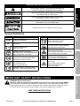
Owner’s Manual & Safety Instructions
Save This Manual Keep this manual for the safety warnings and precautions, assembly,
operating, inspection, maintenance and cleaning procedures. Write the product’s serial number in the
back of the manual near the assembly diagram (or month and year of purchase if product has no number).
Keep this manual and the receipt in a safe and dry place for future reference.
Using an engine indoors
CAN KILL YOU IN MINUTES.
Engine exhaust contains carbon monoxide.
This is a poison you cannot see or smell.
NEVER use inside
a home or garage,
EVEN IF doors and
windows are open.
Only use OUTSIDE
and far away from
windows, doors,
and vents.
Visit our website at: http://www.harborfreight.com
Email our technical support at: [email protected]
REV 14k
When unpacking, make sure that the product is intact
and undamaged. If any parts are missing or broken,
please call 1-888-866-5797 as soon as possible.
Copyright© 2013 by Harbor Freight Tools®. All rights reserved.
No portion of this manual or any artwork contained herein may be reproduced in
any shape or form without the express written consent of Harbor Freight Tools.
Diagrams within this manual may not be drawn proportionally. Due to continuing
improvements, actual product may differ slightly from the product described herein.
Tools required for assembly and service may not be included.
Read this material before using this product.
Failure to do so can result in serious injury.
SAVE THIS MANUAL.
Table of Contents
Safety
Specifications.............................................. 2
Safety��������������������������������������������������������� 3
Setup........................................................... 7
Operationr��������������������������������������������������� 11
Maintenances���������������������������������������������� 18
Troubleshooting.......................................... 22
Warranties.................................................. 24
Parts Lists and Diagrams........................... 28
Specifications
Log Splitter Specifications
Ram Travel
Log Capacity
Towing
Hitch Ball Size
Hydraulic Fluid Reservoir
Setup
Type of Hydraulic Fluid
Wheel Size
Tire Size
Required Tire Air Pressure
Weight
21.85"
23.6" L x 16" Diameter
For off-road use only (not DOT approved);
maximum speed 45 mph
2"
2.25 gallons (8.5 L)
10W AW32, ASLE H-150 or
ISO32 Hydraulic Fluid
15.5" x 4"
4.80-8
60 PSI, Cold
378 lb (filled with fluid)
Engine Specifications
Displacement
212 cc
Horizontal Single Cylinder
4-stroke OHV
Operation
Engine Type
Cooling System
Type
Capacity
Fuel
Engine Oil
Type SAE
Maintenance
Capacity
Run Time @ 50% Load
with full tank
Sound Level at 22 feet
Bore x Stroke
Compression Ratio
Rotation viewed from PTO
(power takeoff - the output shaft)
Spark Plug
Valve Clearance
Speed
Meets EPA phase III
emissions standards
Forced air cooled
87+ octane unleaded gasoline
0.9 Gallon (3.6 Liter)
10W-30 above 32° F
5W-30 at 32° F or below
0.5 Quart
3 hr.
104 dB
70 mm x 55 mm
8.5:1
Counterclockwise
Type
NGK® BP-6ES
NHSP® / Torch® F6TC
Gap
Intake
Exhaust
Idle
0.7 – 0.8 mm
0.10 – 0.15 mm
0.15 – 0.20 mm
1800 ± 50 RPM
The emissions control system for this Engine is warranted for standards set by the
U.S. Environmental Protection Agency. For warranty information, refer to the last pages of this manual.
Page 2
For technical questions, please call 1-888-866-5797.
ITEM 61594
WARNING SYMBOLS AND DEFINITIONS
This is the safety alert symbol. It is used to alert you to potential
personal injury hazards. Obey all safety messages that
follow this symbol to avoid possible injury or death.
Safety
Indicates a hazardous situation which, if not avoided,
will result in death or serious injury.
Indicates a hazardous situation which, if not avoided,
could result in death or serious injury.
Indicates a hazardous situation which, if not avoided,
could result in minor or moderate injury.
Addresses practices not related to personal injury.
RPM
HP
Property or Statement
Revolutions Per Minute
Horsepower
Read the manual before
set-up and/or use.
WARNING marking concerning
Risk of Eye Injury. Wear ANSI-approved
safety goggles with side shields.
WARNING marking concerning Risk of
Facial Injury from flying debris. Wear
ANSI‑approved full face shield.
WARNING marking concerning
Risk of Hearing Loss.
Wear hearing protection.
WARNING marking concerning Risk of
Foot Injury. Wear steel-toe work boots.
Symbol
Property or Statement
WARNING marking concerning
Risk of Hand Injury. Wear
heavy-duty work gloves.
WARNING marking concerning
Crushing Hazard. Keep hands and
feet away from moving parts.
WARNING marking concerning
Risk of Respiratory Injury.
Operate engine OUTSIDE and far away
from windows, doors, and vents.
WARNING marking concerning
Risk of Fire while handling fuel.
Do not smoke while handling fuel.
WARNING marking concerning
Risk of Fire.
Do not refuel while operating.
Keep flammable objects
away from engine.
Operation
Symbol
Setup
Symbol Definitions
IMPORTANT SAFETY INSTRUCTIONS
Maintenance
WARNING! Read all instructions.
Failure to follow all instructions listed below may result in fire, serious injury and/or DEATH.
The warnings and precautions discussed in this manual cannot cover all possible conditions and
situations that may occur. It must be understood by the operator that common sense and caution
are factors which cannot be built into this product, but must be supplied by the operator.
SAVE THESE INSTRUCTIONS
ITEM 61594
For technical questions, please call 1-888-866-5797.
Page 3
Set Up Precautions
1. Gasoline fuel and fumes are flammable, and
potentially explosive. Use proper fuel storage
and handling procedures. Do not store fuel
or other flammable materials nearby.
Safety
2. Have multiple ABC class fire extinguishers nearby.
3. Operation of this equipment may create sparks that
can start fires around dry vegetation.
A spark arrestor may be required. The operator
should contact local fire agencies for laws or
regulations relating to fire prevention requirements.
4. Set up and operate only in a well‑ventilated
area on a level, dry and solid surface
with wheels chocked.
5. Wear ANSI-approved safety goggles, heavy-duty
work gloves, and dust mask/respirator during set up.
6. Use only lubricants and fuel recommended
in the Specifications chart of this manual.
Operating Precautions
CARBON MONOXIDE HAZARD
Using an engine indoors
CAN KILL YOU IN MINUTES.
Engine exhaust contains
carbon monoxide. This is a poison
you cannot see or smell.
1.
8. Do not use Splitter on logs longer than
23.6" or with a diameter greater than 8".
Setup
9. Hold the rounded, bark side of logs when
loading or positioning, never the ends. Do
not place hands or any body parts between
a log and any part of the Log Splitter.
10. Do not load or unload logs while
the splitter wedge is moving.
11. Do not split logs across the grain. Doing so will
damage the Log Splitter and could cause pieces of
log to be thrown, injuring the operator or bystanders.
NEVER use inside a home or garage,
EVEN IF doors and windows are open.
12. Do not split more than one log at a time. A
piece of log can unexpectedly be thrown from
the machine, causing severe personal injury.
Operation
13. Remove split logs away from the Log
Splitter immediately. Split logs left near
the Log Splitter are a tripping hazard.
14. Do not tow the Log Splitter on roads or highways.
This product is not D.O.T. compliant.
Only use OUTSIDE and far away from windows,
doors, and vents.
2. Keep children away from the equipment,
especially while it is operating.
3. DO NOT OPERATE WITH ANY GUARD
DISABLED, DAMAGED, OR REMOVED. Keep
guards in place and in good working order.
4. Wear ANSI-approved safety goggles under
full face shield, heavy-duty work gloves
and steel-toe work boots during use.
Maintenance
5. Keep clear of moving parts and log
during operation. Crushing hazard.
6. Do not check for hydraulic leak with hands.
High-pressure fluid can be forced under the skin
resulting in serious injury. Inspect hydraulic lines
for leakage before use; do not use if leaks found.
7. Do not split wood containing foreign
objects (nails, for example).
Page 4
15. Keep bystanders away during operation.
16. Fire Hazard! Do not fill gas tank while engine is
running. Do not operate if gasoline has been spilled.
Clean spilled gasoline before starting engine.
Do not operate near pilot light or open flame.
17. Do not touch engine during use.
Let engine cool down after use.
18. Never store fuel or other flammable
materials near the engine.
19. Industrial applications must follow
OSHA requirements.
20. Do not leave the equipment unattended when it is
running. Turn off the equipment (and remove safety
keys, if available) before leaving the work area.
21. The equipment can produce high noise levels.
Prolonged exposure to noise levels
above 85 dBA is hazardous to hearing.
Wear ear protection when operating the equipment
or when working nearby while it is operating.
For technical questions, please call 1-888-866-5797.
ITEM 61594
Operating Precautions (continued)
25. Stay alert, watch what you are doing and use
common sense when operating this piece of
equipment. Do not use while tired or under the
influence of drugs, alcohol or medication.
26. Do not overreach. Keep proper footing and
balance at all times. This enables better control
of the equipment in unexpected situations.
27. Use this equipment with both hands only.
Using equipment with only one hand
can easily result in loss of control.
28. Dress properly. Do not wear loose clothing or
jewelry. Keep hair, clothing and gloves away
from moving parts. Loose clothes, jewelry or
long hair can be caught in moving parts.
29. Parts, especially exhaust system components,
get very hot during use. Stay clear of hot parts.
30. Do not cover the equipment during operation.
34. WARNING: This product contains or, when
used, produces a chemical known to the State
of California to cause cancer and birth defects
or other reproductive harm. (California Health
& Safety Code § 25249.5, et seq.)
35. When spills of fuel or oil occur, they must be
cleaned up immediately. Dispose of fluids and
cleaning materials as per any local, state, or
federal codes and regulations. Store oil rags in
a bottom-ventilated, covered, metal container.
36. Keep hands and feet away from moving parts.
Do not reach over or across
equipment while operating.
37. Before use, check for misalignment or binding of
moving parts, breakage of parts, and any other
condition that may affect the equipment’s operation.
If damaged, have the equipment serviced
before using. Many accidents are caused
by poorly maintained equipment.
38. Use the correct equipment for the application.
Do not modify the equipment and do not use the
equipment for a purpose for which it is not intended.
Service Precautions
1. Before service, maintenance, or cleaning:
a. Turn the engine switch to its “OFF” position.
b. Allow the engine to completely cool.
c. Then, remove the spark plug cap
from the spark plug.
2. Keep all safety guards in place and in
proper working order. Safety guards include
muffler, air cleaner, mechanical guards,
and heat shields, among other guards.
3. Do not alter or adjust any part of the
equipment or its engine that is sealed by the
manufacturer or distributor. Only a qualified
service technician may adjust parts that may
increase or decrease governed engine speed.
4. Wear ANSI-approved safety goggles,
heavy‑duty work gloves, and
dust mask/respirator during service.
5. Maintain labels and nameplates on the equipment.
These carry important information.
If unreadable or missing, contact
Harbor Freight Tools for a replacement.
6. Have the equipment serviced by a qualified repair
person using only identical replacement parts.
This will ensure that the safety of the equipment
is maintained. Do not attempt any service or
maintenance procedures not explained in this
manual or any procedures that you are uncertain
about your ability to perform safely or correctly.
7. Store equipment out of the reach of children.
8. Follow scheduled engine and
equipment maintenance.
ITEM 61594
Safety
33. Do not operate the equipment with known
leaks in the engine’s fuel system.
Setup
24. Do not operate in explosive atmospheres,
such as in the presence of flammable
liquids, gases, or dust. Gasoline-powered
engines may ignite the dust or fumes.
32. Use the equipment, accessories, etc., in
accordance with these instructions and in the
manner intended for the particular type of
equipment, taking into account the working
conditions and the work to be performed.
Use of the equipment for operations different from
those intended could result in a hazardous situation.
Operation
23. Use only accessories that are recommended
by Harbor Freight Tools for your model.
Accessories that may be suitable for one
piece of equipment may become hazardous
when used on another piece of equipment.
31. Keep the equipment, engine, and
surrounding area clean at all times.
For technical questions, please call 1-888-866-5797.
Page 5
Maintenance
22. People with pacemakers should consult their
physician(s) before use. Electromagnetic fields in
close proximity to a heart pacemaker could cause
pacemaker interference or pacemaker failure.
Caution is necessary when near the
engine’s magneto or recoil starter.
Service Precautions (continued)
Refueling:
Safety
1. Do not smoke, or allow sparks, flames,
or other sources of ignition around the
equipment, especially when refuelling.
2. Do not refill the fuel tank while the
engine is running or hot.
3. Do not fill fuel tank to the top.
Leave a little room for the fuel to expand as needed.
TO PREVENT FUEL LEAKAGE AND
FIRE HAZARD, do not fill fuel above
the bottom of fuel strainer.
Max Fuel
DO NOT OVERFILL!
4. Refuel in a well-ventilated area only.
5. Wipe up any spilled fuel and allow excess
to evaporate before starting engine.
To prevent FIRE, do not start the engine
while the smell of fuel hangs in the air.
Setup
SAVE THESE INSTRUCTIONS.
Operation
Maintenance
Page 6
For technical questions, please call 1-888-866-5797.
ITEM 61594
Set Up
Washer (8)
Tow Bar (42)
Lock Nut (5)
Assembly
1. Use Bolt (15) and Lock Pin (16) to attach the
Support Leg (14) underneath the Tow Bar (42).
Secure the Bolt using Washer (8) and Lock Nut (5)
and secure the Lock Pin using its clip.
Lock pin (16)
Support Leg (14)
SAFETY
Read the ENTIRE IMpORTANT SAFETY
INFORMATION section at the beginning of this
manual including all text under subheadings
therein before set up or use of this product.
Bolt (15)
2. Attach Front Tow Bar (9) to end of Tow Bar using
Bolts (2), Washers (3), and Lock Nuts (4).
Lock Washer (3)
Nut (4)
Front Tow
Bar (9)
Tow Bar
Bolt (2)
SETUp
Assembly Step 1: Attach Support Leg
Assembly Step 2: Attach Front Tow Bar
Tow Bar
Lock
Nut (4)
Washer (3)
Bolt (2)
3. Attach Tow Bar to bracket on top of Fluid Tank (51)
using Bolts (2), Washers (3), and Lock Nuts (4).
OpERATION
Fluid
Tank (51)
Assembly Step 3: Attach Fluid Tank
Wheel (48)
4. Wheel Assembly:
b. Slide the Wheel onto an axle on the Fluid Tank.
c. Place a Washer (47), then
a Castle Nut (46) onto the axle.
Wheel (48)
Fluid
Tank
d. Tighten the Castle Nut until the Wheel can spin
with slight resistance. Loosen the Castle Nut about
1/6 turn from the point resistance is felt,
and insert the Cotter Pin (74).
Washer
(47)
Castle
Nut (46)
Cotter
pin (74)
Axle
Cap (44)
e. Bend the end of the Cotter Pin
back to lock it in place.
f. Press the Axle Cap (44) securely in place.
Assembly Step 4: Attach Wheels
ITEM 61594
For technical questions, please call 1-888-866-5797.
Page 7
MAINTENANCE
a. Pack grease into the center of one
Wheel’s (48) hub from both sides.
R-pin (23)
Beam (21)
asm.
5. Beam Assembly:
SAFETY
a. Place Beam (21) assembly on top of
the Fluid Tank and Tow Bar.
b. Line up the bracket underneath the
Beam with the tube at the top of the
Fluid Tank, and insert the Hinge Pin (41).
Secure the Hinge Pin with the R-Pin (23).
Lock
Nut (4)
Hose
(35)
Washer (3)
Hinge
pin (41)
O-Ring
(34)
c. Secure the brackets at the front of
the Tow Bar together using Bolts (11),
Washers (3), and Lock Nuts (4).
d. Attach the O-Ring (34) and Hose (35) marked
“Fluid Tank” to the threaded connector at the top
of the Fluid Tank. Wrench-tighten it securely.
Tow Bar
SETUp
Fluid
Tank
Bolt (11)
6. Engine and pump Assembly:
a. Attach Engine Connecting Plate (58) to the pedestal
on the back of the Fluid Tank using Bolts (66),
Lock Washers (28), and Lock Nuts (61).
b. Slide a Hose Clamp (57) over the Return Hose (56).
c. Slip the Return Hose over the Fluid Connector (17).
OpERATION
d. Slide the Hose Clamp over the connection,
and tighten its screw to secure it in place.
e. Attach an O-Ring (34) to the Connector (72)
on the Hydraulic Pump (59). Connect the
unconnected Hose (38) marked “Pump” from
the Control Valve (32) to the Connector on the
Hydraulic Pump. Wrench-tighten it securely.
Assembly Step 5: Attach Beam Assembly
Fluid
Connector
(17)
O-Ring (34)
Connector (72)
Engine
Connecting
plate (58)
Lock Nut (61)
and
Lock Washer (28)
Bolt (66)
Return
Hose (56)
Assembly Step 6: Attach Engine and pump
Log
Cradles (73)
MAINTENANCE
7. Insert the Log Cradles (73) into the brackets
on the sides of the Beam (21) angled outward.
Secure them in place with a Cotter Pin (45).
Bend the Cotter Pins back to secure them in place.
Cotter
pin (45)
Beam (21)
Cotter
pin (45)
Assembly Step 7: Attach Log Cradles
Page 8
For technical questions, please call 1-888-866-5797.
ITEM 61594
High Altitude Operation Above 3000 feet
NOTICE: Warranty void if necessary adjustments are not made for high altitude use.
At high altitudes, the engine’s carburetor, governor (if so equipped), and any other parts that control the fuel-air
ratio will need to be adjusted by a qualified mechanic to allow efficient high-altitude use and to prevent damage
to the engine and any other devices used with this product. The fuel system on this engine may be influenced by
operation at higher altitudes. Proper operation can be ensured by installing an altitude kit at altitudes higher than
3000 feet above sea level. At elevations above 8000 feet, the engine may experience decreased performance, even
with the proper main jet. Operating this engine without the proper altitude kit installed may increase the engine’s
emissions and decrease fuel economy and performance. The kit should be installed by a qualified mechanic.
Safety
WARNING! TO PREVENT SERIOUS INJURY FROM FIRE:
Follow instructions in a well-ventilated area away from ignition sources.
If the engine is hot from use, shut the engine off and wait for it to cool before proceeding. Do not smoke.
1. Turn off the engine.
2. Close the fuel valve.
CAUTION! Carburetor bowl may have gas in it which will leak upon removing the bolt.
4. Unthread the bolt holding the fuel cup.
5. Remove the bolt, Bolt Seal, fuel cup, Fuel Cup Seal and Main Jet from the body of the carburetor assembly.
A carburetor screwdriver (not included) is needed to remove and install the Main Jet.
Setup
3. Place a bowl under the fuel cup to catch any spilled fuel.
Note: The mixing tube is held in place by the Main Jet and might fall out when it is removed.
If it falls out, replace it in the same orientation before replacing the Main Jet.
6. Replace the Main Jet with the replacement Main Jet needed for your altitude range (part 1a or 2a).
CAUTION: Do not cross thread bolt when tightening.
Finger tighten first and then use a wrench to
make sure the bolt is properly threaded.
Carburetor
Assembly
Fuel Cup Seal
8. Wipe up any spilled fuel and allow excess to evaporate
before starting engine. To prevent FIRE, do not start
the engine while the smell of fuel hangs in the air.
Mixing Tube
High Altitude Kit Parts List - A
Main Jet
Part
1a
2a
3a
4a
Description
Main Jet 3000-6000 ft.
Main Jet 6000-8000 ft.
Bolt Seal
Fuel Cup Seal
Qty
1
1
1
1
(might remain
inside carburetor)
Fuel Cup
Bolt Seal
Bolt
ITEM 61594
For technical questions, please call 1-888-866-5797.
Page 9
Maintenance
7. Replace the Fuel Cup Seal (4a), fuel cup,
Bolt Seal (3a), and bolt. Tighten in place.
Operation
Note: The Fuel Cup Seal and Bolt Seal may be damaged during removal
and should be replaced with the new ones from the kit.
TO PREVENT SERIOUS INJURY:
Operate only with proper spark arrestor installed.
Safety
Operation of this equipment may create sparks that can start fires around dry vegetation.
A spark arrestor may be required.
The operator should contact local fire agencies for laws or regulations
relating to fire prevention requirements.
Components and Controls
Control
Handle
Cutting Wedge
Engine
Switch
Tow Bar
Setup
Support
Leg
Fluid Drain Plug
Fluid Fill Plug
Operation
Log Cradle
Throttle
Choke
Fuel Cap
Fuel
Valve
Starter
Handle
Maintenance
Dipstick
Page 10
For technical questions, please call 1-888-866-5797.
Oil Drain
Plug
ITEM 61594
Operation
Workpiece and Work Area Set Up
1. Designate a work area that is clean and well‑lit.
The work area must not allow access by children
or pets to prevent distraction and injury.
2. There must not be objects, such as utility lines,
nearby that will present a hazard while working.
3. Maximum log size for this Log Splitter is
23.6" long and 8" in diameter. Attempting to
cut logs that exceed those measurements is
dangerous and may damage the Log Splitter.
4. Use a chainsaw (not included) to cut logs
square on each end before splitting. Log ends
that are not cut square can slide out while
splitting and cause a safety hazard or cause
excessive force to Log Splitter components.
Safety
Read the ENTIRE IMPORTANT SAFETY INFORMATION section at the beginning of this manual
including all text under subheadings therein before set up or use of this product.
5. Do not split wood containing foreign objects
(nails, for example). Do not use odd-shaped,
uneven logs or logs that are knotted or curved.
Setup
Engine and Equipment Pre-Start Checks
Inspect engine and equipment looking for damaged, loose, and missing parts before set up and starting.
If any problems are found, do not use equipment until fixed properly.
Checking and Filling Engine Oil
1. Make sure the engine is stopped and is level.
2. Close the Fuel Valve.
3. Clean the top of the Dipstick and the
area around it. Remove the Dipstick
by threading it counterclockwise, and
wipe it off with a clean, lint free rag.
Full level
Full level
4. Reinsert the Dipstick without threading it in and
remove it to check the oil level. The oil level
should be up to the full level as shown above.
5. If the oil level is at or below the low mark add the
appropriate type of oil until the oil level is at the
proper level. SAE 10W‑30 oil is recommended
for general use. (The SAE Viscosity Grade chart
on page 20 in the Service section shows other
viscosities to use in different average temperatures.)
6. Thread the dipstick back in clockwise.
Operation
NOTICE: Your Warranty is VOID if the engine’s
crankcase is not properly filled with oil before
each use. Before each use, check the oil level.
Do not run the engine with low or no engine oil.
Running the engine with no or low engine oil
WILL permanently damage the engine.
NOTICE: Do not run the engine with too little oil.
The engine will be permanently damaged.
WARNING! TO PREVENT SERIOUS
INJURY FROM FIRE:
Fill the fuel tank in a well-ventilated area
away from ignition sources. If the engine
is hot from use, shut the engine off and
wait for it to cool before adding fuel. Do not smoke.
1. Clean the Fuel Cap and the area around it.
2. Unscrew and remove the Fuel Cap.
3. Remove the Strainer and remove any dirt
and debris. Then replace the Strainer.
Note: Do not use gasoline containing more than
10% ethanol (E10). Do not use E85 ethanol. Add fuel
stabilizer to the gasoline or the Warranty is VOID.
ITEM 61594
Note: Do not use gasoline that has been stored in a
metal fuel container or a dirty fuel container. It can
cause particles to enter the carburetor, affecting
engine performance and/or causing damage.
4. If needed, fill the Fuel Tank to about 1 inch under
the fill neck of the Fuel Tank with 87 octane or
higher unleaded gasoline that has been treated
with a fuel stabilizer additive. Follow fuel stabilizer
manufacturer’s recommendations for use.
5. Then replace the Fuel Cap.
6. Wipe up any spilled fuel and allow excess
to evaporate before starting engine.
To prevent FIRE, do not start the engine
while the smell of fuel hangs in the air.
For technical questions, please call 1-888-866-5797.
Page 11
Maintenance
Checking and Filling Fuel
Engine and Equipment Pre-Start Checks (continued)
Checking and Filling Hydraulic Fluid
Safety
NOTICE: Your Warranty is VOID if the Log Splitter’s
hydraulic fluid tank is not properly filled with fluid
before each use. BEFORE FIRST USE, FLUID TANK
MUST BE FILLED WITH HYDRAULIC FLUID (NOT
INCLUDED). Before each use thereafter, check
the hydraulic fluid level of the Log Splitter when
fluid is cold. Operating without sufficient fluid
in the reservoir can badly damage the pump.
1. Fluid Tank comes empty. To add
hydraulic fluid before first use:
a. Make sure the Log Splitter is level.
b. Remove the Fluid Fill Plug from the Fluid Tank.
c. Fill the Tank with hydraulic fluid (not included).
Refer to the Specifications chart of this
manual for amount and type of fluid to use.
Setup
d. Replace the Fluid Fill Plug.
2. To check fluid level before each subsequent use:
a. Make sure the Log Splitter is level.
b. Remove the Fluid Fill Plug from the Fluid Tank.
c. Check the hydraulic fluid level using the
dipstick attached to the Fluid Fill Plug.
d. Add sufficient fluid (not included) as needed to
bring up to full level. Refer to the Specifications
chart of this manual for type of fluid to use.
e. Replace the Fluid Fill Plug.
3. After completing Step 1 or 2 above, start the
Engine following directions in next section and
use the Control Handle to cycle the Cutting
Wedge forward and back several times to
remove excess air from the Fluid Tank.
4. Retract the Cutting Wedge, turn the Engine
Switch to its “OFF” position, and recheck
the hydraulic fluid level and add fluid if
necessary to bring up to full level.
5. Replace the Fluid Fill Plug.
WARNING! Do not open Fluid Tank while Log
Splitter is running or while fluid is still hot from use.
Starting the Engine
Operation
Before Starting the Engine
Before starting the engine:
a. Inspect the equipment and engine.
b. Fill the engine with the proper amount and type of both unleaded gasoline and oil.
c. Fill the Fluid Tank with the proper amount and type of hydraulic fluid.
Manual Start
Maintenance
1. To start a cold engine, move the Choke to the
CHOKE position.
To restart a warm engine, leave the
Choke in the RUN position.
Page 12
1
For technical questions, please call 1-888-866-5797.
ITEM 61594
3. Slide the Throttle or Speed Control Lever to 1/3
away from the SLOW position (the “turtle”).
Safety
2
2. Open the Fuel Valve.
O
4. Turn the Engine Switch on.
5. Grip the Starter Handle of the Engine loosely and pull
it slowly several times to allow the gasoline to flow into
the Engine’s carburetor. Then pull the Starter Handle
gently until resistance is felt. Allow Cable to retract fully
and then pull it quickly. Repeat until the engine starts.
ON
I
4
Operation
OFF
ON
Setup
3
5
Note: Do not let the Starter Handle snap back against the engine.
Hold it as it recoils so it doesn't hit the engine.
Note: Moving the Choke Lever too
fast could stall the engine.
Maintenance
6. Allow the Engine to run for several seconds.
Then, if the Choke lever is in the CHOKE position,
move the Choke Lever very slowly to its RUN position.
6
IMPORTANT: Allow the engine to run at no load for five minutes
with no load after each start‑up so that the engine can stabilize.
7. Adjust the Throttle as needed.
ITEM 61594
For technical questions, please call 1-888-866-5797.
Page 13
Starting the Engine (continued)
Break-in Period:
a. Breaking-in the engine will help to ensure proper equipment and engine operation.
b. The operational break-in period will last about 3 hours of use. During this period:
Safety
• Do not apply a heavy load to the equipment.
• Do not operate the engine at its maximum speed.
c. The maintenance break-in period will last about 20 hours of use.
• Change the engine oil after this period.
Under normal operating conditions subsequent maintenance follows the
schedule explained in the Maintenance section on page 18.
Log Splitter Operating Instructions
1. Check the hydraulic fluid level; fill as necessary.
Setup
2. Ensure that the Support Leg is down and place
wheel chocks (not included) on each side of the
wheels to keep the Log Splitter from moving.
3. Follow procedures in previous
section to start the engine.
IMPORTANT: Hydraulic fluid temperature must be
above 10° F (-12° C) before operating the Log Splitter
or damage to the hydraulic pump may result. If outdoor
temperature is below 32° F (0° C) use the Control Handle
to cycle the Cutting Wedge forward and back several
times to warm the hydraulic fluid before splitting wood.
4. Stand in the correct operator position as shown
in Figure A when operating the Log Splitter.
5. Hold the rounded, bark side of log and position
it lengthwise in the direction of the grain on the
Beam of the Splitter between the Log Cradles.
Place one end of log against the end plate.
6. The log must be stable so that it will split properly.
Hold the top of the log at its center, if safe to do so.
Release log once Cutting Wedge engages it.
7. Push the Control Handle forward to drive the
Cutting Wedge forward into the log, splitting it.
8. Remove split log pieces and place the next
log against the opposite end plate.
9. Push the Control Handle backward to
drive the Cutting Wedge in the opposite
direction into the log, splitting it.
Operation
10. Turn off the Log Splitter engine after use. Clean,
then cover the tool and store in a dry, level,
well-ventilated area out of reach of children.
Correct Operator
Position
Figure A: Operator Position
Removing a Stuck Log
Maintenance
A log that is too stringy or tough to split completely
can become stuck on the Cutting Wedge if the
Wedge becomes embedded in the log and
the log doesn’t completely split and separate.
If this happens, follow the directions below.
1. Relieve pressure on log and end plate
by retracting Cutting Wedge slightly.
2. Turn the Engine Switch to its “OFF” position
and disconnect the spark plug cap.
3. Remove the stuck log from the Cutting Wedge
manually with a sledge hammer and pry bar.
Page 14
WARNING! Be extremely careful when removing
the log as pieces may fly off as they separate from
the Wedge. Never attempt to remove a stuck log
by using the hydraulic force of the Log Splitter,
modifying the Log Splitter, or adding attachments
to the Log Splitter. Personal injury could result
from log or metal pieces flying out at high speed,
or the Log Splitter could become damaged.
4. Do not attempt to re-split a stuck log once it
has been removed from the Wedge. Manually
split with a maul, or cut with a chainsaw.
For technical questions, please call 1-888-866-5797.
ITEM 61594
Stopping the Engine
OFF
I
Safety
1. To stop the engine in an emergency,
turn the Engine Switch off.
O
2. Under normal conditions, use the following procedure:
a. Slide the Throttle or Speed Control
Lever to SLOW (the “turtle”).
Setup
b. Turn the Engine Switch off.
c. Close the Fuel Valve.
d. Stay clear of Cutting Wedge while moving Control
Handle back and forth to relieve hydraulic pressure.
NOTICE
Maintenance
Operation
See Long-Term Storage on page 21
for complete storage instructions.
ITEM 61594
For technical questions, please call 1-888-866-5797.
Page 15
Towing
Safety
DO NOT TRANSPORT THE LOG SPLITTER ON
PUBLIC ROADS. The Log Splitter is not certified by the
Department of Transportation for use on public roads.
WARNING! The Support Leg must always be
secured in the horizontal position for towing and
returned to the down position before use.
1. Check tire condition and air pressure.
5. Make sure the hitch (not included) is
compatible with the Hitch Coupler. The
Coupler will accept a 2 inch hitch ball.
2. Make sure wheel lug nuts/bolts
are properly tightened.
3. Make sure hitch, coupler, tow bar, and other
equipment that connect the Log Splitter and the
tow vehicle are properly secured and adjusted.
4. Before towing the Log Splitter, remove the Lock
Pin (16) and lift the Support Leg (14) up so that it
is parallel to the Beam Assembly. Then, replace
the Lock Pin into the Horizontal Transport Hole
and secure using its clip. Refer to Figure B.
6. Pull up and down on the Hitch Coupler to
make sure the hitch ball is fitting snugly in
the Hitch Coupler. There should be no play
between the hitch ball and Hitch Coupler.
7. Empty fuel tank before towing. Do not
carry cargo or wood on Log Splitter.
8. Always use the Safety Chains during towing. Do
not tow the Log Splitter at speeds above 45 MPH.
9. Follow all safety warnings for towing in the
towing vehicle manufacturer’s manual.
Setup
Horizontal
Transport Hole
Lock Pin
(16)
Operation
Support Leg locked
in towing position.
Support Leg (14)
Figure B: Preparation for Towing
Tire Care
Checking Tire Pressure
Maintenance
Note: Underinflated tires can decrease handling,
stopping performance, traction, tire life, and
load‑carrying capability, in addition to causing other
negative and hazardous effects, including tire failure.
Overinflated tires are at greater risk of an impact
break, where the tread and casing break when
striking a hard edge, often opening a huge gash
across the tread. Incorrect inflation pressure
also increases tires wear rate. Therefore, it is
important to keep tires inflated properly.
Check all tires’ pressure at least monthly,
due to the following factors:
This Log Splitter has 60 PSI recommended cold tire
inflation pressure. The term “cold” in this manual does
not refer to the temperature outside, but it refers to the
fact that a tire that has not been driven for a period is
cooler (and therefore has lower pressure) than a tire
that has been driven on. Tires heat up while being
driven on. To check (or fill to) a tire’s cold inflation,
the tire must have not been driven for more than a
mile or two for at least three hours. If you check a
tires pressure when it is not “cold”, the pressure will
appear higher than the actual cold tire inflation.
• Most tires naturally lose air gradually.
• Tires can suddenly lose air if the tire
strikes a pothole, curb, or other object.
• It is usually not possible to determine
underinflation of radial tires by visual inspection.
Page 16
For technical questions, please call 1-888-866-5797.
ITEM 61594
Tire Care (continued)
1. Locate the recommended tire pressure on the
vehicle’s tire information placard, certification label,
or in the owner’s manual. This Log Splitter has
60 PSI recommended cold tire inflation pressure.
4. If the tire pressure is too low, note the difference
between the measured tire pressure and the
correct tire pressure. These “missing” pounds
of pressure are what you will need to add.
2. Measure and record the tire pressure of all tires.
5. At a service station, add the missing pounds of
air pressure to each tire that is underinflated.
3. If the tire pressure is too high in any of the tires
and the tires have not been driven for at least
three hours, slowly release air by gently pressing
on the tire valve stem with the edge of your
tire gauge until you get to the correct pressure.
If the vehicle has been driven within the past three
hours and the tire pressure is too high on any tires,
then recheck the pressure once the tires have been
allowed to sit motionless for at least three hours.
6. Check all the tires to make sure they
have the same air pressure.
Safety
Steps for Maintaining Proper Tire Pressure
7. If the tires’ pressure was not measured “cold”,
then the pressure should be rechecked
with the tires cold as soon as possible.
Setup
Tire Size
To maintain safety, only purchase new tires of the same size as the original tires.
Look at the Tire and Loading Information Placard, the Specifications Chart in this manual, or the sidewall
of the tire being replaced. If you have any doubt about selecting the correct size, consult a tire dealer.
Tire Tread
The tire tread provides traction that prevents your vehicle from slipping, especially if the road is wet or icy.
Tires are unsafe and should be replaced when the tread is worn down to 1/16″.
Measure tread depth using a tread depth indicator (not included).
Tire Rotation
Operation
Every 5,000 miles the left and right tires should be switched.
This will cause the tires to wear more evenly and last longer.
Tire Balance and Alignment
The tires need to be balanced to prevent vibration when driving. This involves attaching small
weights to the rim to offset small differences in rim and tire weight. The tires also need to be
aligned properly. Alignment is the orientation of the tires to the road surface and their being
parallel. This helps the tires to wear evenly, and provide better traction. Both tire balance and
alignment require specialized equipment that is not provided with this equipment.
Tire Repair
Maintenance
To properly repair a punctured tire, the hole needs to be properly plugged and patched from the
inside of the tire. Tread punctures can be repaired if they are not too large. Sidewall punctures
should not be repaired, the tire needs to be replaced if the sidewall is damaged. Tires should
be removed from the rim to be inspected before being plugged and patched. A qualified
mechanic should remove the tire from the rim, perform the repair, and remount the tire.
ITEM 61594
For technical questions, please call 1-888-866-5797.
Page 17
Maintenance
WARNING
Safety
TO PREVENT SERIOUS INJURY FROM ACCIDENTAL STARTING: Turn the Power Switch
of the equipment to its “OFF” position, wait for the engine to cool, disconnect the spark
plug cap, and move the Control Handle forward and back to relieve hydraulic system
pressure before performing any inspection, maintenance, or cleaning procedures.
TO PREVENT SERIOUS INJURY FROM EQUIPMENT FAILURE: Do not use damaged equipment. If
abnormal noise, vibration, or excess smoking occurs, have the problem corrected before further use.
Follow all service instructions in this manual. The engine may fail critically if not serviced properly.
Many maintenance procedures, including any not detailed in this manual, will need to be performed
by a qualified technician for safety. If you have any doubts about your ability to safely service the
equipment or engine, have a qualified technician service the equipment instead.
Cleaning, Maintenance, and Lubrication Schedule
Setup
Note: This maintenance schedule is intended solely as a general guide. If performance decreases or if
equipment operates unusually, check systems immediately. The maintenance needs of each piece of equipment
will differ depending on factors such as duty cycle, temperature, air quality, fuel quality, and other factors.
Note: The following procedures are in addition to the regular checks and maintenance
explained as part of the regular operation of the engine and equipment.
Before
Each Use
Procedure
1. Brush off outside of engine
Monthly or
Every 3 mo. or Every 6 mo. or
every 20
50 hr. of use 100 hr. of use
hr. of use
Yearly or
every 300
hr. of use
Every
2 Years
2. Check engine oil level
3. Check hydraulic fluid level
Check air cleaner
Check sediment cup
Operation
Change engine oil
1. Change hydraulic fluid
2. Check and clean spark plug
Clean air filter
1. Check/adjust idle speed
*
2. Check/adjust valve clearance
3. Clean fuel tank, strainer
and carburetor
**
4. Clean carbon build-up from
combustion chamber
Replace fuel line if necessary
*Service more frequently when used in dusty areas.
**These items should be serviced by a qualified technician.
**
**
Maintenance
Bleeding the Hydraulic System
1. Remove the Fluid Fill Plug and check the hydraulic
fluid level using the dipstick attached to the Plug.
2. Add sufficient fluid (not included) as needed to
bring up to full level. Replace Fluid Fill Plug.
4. Retract the Cutting Wedge, recheck
the hydraulic fluid level and add fluid if
necessary to bring up to full level.
5. Replace the Fluid Fill Plug.
3. Start the engine and use the Control Handle to
cycle the Cutting Wedge forward and back several
times to remove excess air from the Fluid Tank.
Page 18
For technical questions, please call 1-888-866-5797.
ITEM 61594
Change the hydraulic fluid in the Log
Splitter after every 100 hours of use.
1. Allow hydraulic fluid to cool completely before
changing. Place an appropriate three gallon or
greater capacity container under the Fluid Tank.
2. Remove the Fluid Drain Plug and drain the
fluid reservoir. Dispose of the old hydraulic
fluid in accordance with local regulations.
3. Replace the Fluid Drain Plug, remove the Fluid
Fill Plug and fill the Fluid Tank with 2.25 gallons
(8.5 liters) of fresh 10W AW32, ASLE H-150
or ISO32 hydraulic fluid (not included).
Note: If using the Log Splitter for extended
periods in outdoor temperatures above 70° F, the
use of Dextron III automatic transmission fluid
(not included) is recommended. DO NOT mix
Dextron III with other types of hydraulic fluid—drain
reservoir completely if substituting Dextron III.
4. Check the hydraulic fluid level using the
dipstick attached to the Fluid Fill Plug.
5. Add sufficient fluid (not included) as needed to
bring up to full level. Replace Fluid Fill Plug.
Safety
Replacing Hydraulic Fluid
6. Start the engine and use the Control Handle to
cycle the Cutting Wedge forward and back several
times to remove excess air from the Fluid Tank.
7. Retract the Cutting Wedge, recheck
the hydraulic fluid level and add fluid if
necessary to bring up to full level.
Setup
8. Replace the Fluid Fill Plug.
Checking and Filling Fuel
1. Clean the Fuel Cap and the area around it.
2. Unscrew and remove the Fuel Cap.
3. Remove the Strainer and remove any dirt
and debris. Then replace the Strainer.
Note: Do not use gasoline containing more than
10% ethanol (E10). Do not use E85 ethanol. Add fuel
stabilizer to the gasoline or the Warranty is VOID.
Note: Do not use gasoline that has been stored in a
metal fuel container or a dirty fuel container. It can
cause particles to enter the carburetor, affecting
engine performance and/or causing damage.
4. If needed, fill the Fuel Tank to about 1 inch under
the fill neck of the Fuel Tank with 87 octane or
higher unleaded gasoline that has been treated
with a fuel stabilizer additive. Follow fuel stabilizer
manufacturer’s recommendations for use.
Operation
WARNING! TO PREVENT SERIOUS
INJURY FROM FIRE:
Fill the fuel tank in a well-ventilated area
away from ignition sources. If the engine is
hot from use, shut the engine off and wait
for it to cool before adding fuel. Do not smoke.
5. Then replace the Fuel Cap.
6. Wipe up any spilled fuel and allow excess
to evaporate before starting engine.
To prevent FIRE, do not start the engine
while the smell of fuel hangs in the air.
1. Remove the Air Cleaner Cover and the air filter(s)
and check for dirt. Clean as described below.
2. Cleaning:
• For paper filters:
To prevent injury from dust and debris,
wear ANSI-approved safety goggles,
NIOSH‑approved dust mask/respirator, and
heavy-duty work gloves. In a well‑ventilated
area away from bystanders, use pressurized
air to blow dust out of the filter.
ITEM 61594
• For foam filters:
Wash the filter in warm water and mild
detergent several times. Rinse. Squeeze out
excess water and allow it to dry completely.
Soak the filter in lightweight oil briefly,
then squeeze out the excess oil.
3. Install the cleaned filter(s). Secure the
Air Cleaner Cover before use.
For technical questions, please call 1-888-866-5797.
Page 19
Maintenance
Air Filter Element Maintenance
Maintenance (continued)
Engine Oil Change
CAUTION! Oil is very hot during operation and can
cause burns. Wait for engine to cool before changing oil.
Safety
1. Make sure the engine is stopped and is level.
2. Close the Fuel Valve.
7. Add the appropriate type of oil until the oil level is at
the full level. SAE 10W‑30 oil is recommended for
general use.
The SAE Viscosity Grade chart shows other
viscosities to use in different average temperatures.
3. Place a drain pan (not included) underneath
the crankcase’s drain plug.
SAE Viscosity Grades
4. Remove the drain plug and, if possible,
tilt the crankcase slightly to help drain
the oil out. Recycle used oil.
30
5. Replace the drain plug and tighten it.
10W-30
6. Clean the top of the Dipstick and the
area around it. Remove the Dipstick by
threading it counterclockwise, and wipe
it off with a clean, lint free rag.
5W-30
Setup
-20
0
20
40
60
80
Average outdoor temperature
100°F
8. Thread the dipstick back in clockwise.
Full level
Full level
NOTICE: Do not run the engine with too little oil.
The engine will be permanently damaged.
Spark Plug Maintenance
Operation
4. When installing a new spark plug,
adjust the plug’s gap to the specification on the
Specifications chart. Do not pry against the
electrode, the spark plug can be damaged.
Spark
Plug
Cap
5. Install the new spark plug or
the cleaned spark plug into the engine.
• Gasket-style:
Finger-tighten until the gasket
contacts the cylinder head,
then tighten about 1/2-2/3 turn more.
1. Disconnect spark plug cap from end of plug.
Clean out debris from around spark plug.
2. Using a spark plug wrench, remove the spark plug.
Maintenance
3. Inspect the spark plug:
If the electrode is oily, clean it using a clean, dry rag.
If the electrode has deposits on it, polish it using
emery paper. If the white insulator is cracked or
chipped, the spark plug needs to be replaced.
Recommended Spark Plugs
NGK®
NHSP® / TORCH®
BP-6ES
F6TC
• Non-gasket-style:
Finger-tighten until the plug
contacts the cylinder head,
then tighten about 1/16 turn more.
NOTICE: Tighten the spark plug properly.
If loose, the spark plug will cause the
engine to overheat.
If overtightened, the threads in the
engine block will be damaged.
6. Apply dielectric spark plug boot protector
(not included) to the end of the spark plug
and reattach the wire securely.
NOTICE: Using an incorrect spark plug
may damage the engine.
Page 20
For technical questions, please call 1-888-866-5797.
ITEM 61594
Tires
2. Underinflation reduces the load-carrying capacity
of your tow vehicle or trailer, may cause sway and
control problems, and may result in overheating,
causing blowouts or other tire failure.
Long-Term Storage
When the equipment is to remain idle for longer than
20 days, prepare the Engine for storage as follows:
c. Replace spark plug, but leave
spark plug cap disconnected.
1. CLEANING:
Wait for Engine to cool, then clean Engine with
dry cloth. NOTICE: Do not clean using water.
The water will gradually enter the Engine
and cause rust damage. Apply a thin coat
of rust preventive oil to all metal parts.
d. Pull Starter Handle to distribute oil in cylinder.
Stop after one or two revolutions when you
feel the piston start the compression stroke
(when you start to feel resistance).
2. FUEL:
To protect the fuel tank during storage, fill the
tank with gasoline that has been treated with
a fuel stabilizer additive. Follow fuel stabilizer
manufacturer’s recommendations for use. Refer
to Checking and Filling Fuel on page 19.
WARNING! TO PREVENT SERIOUS
INJURY FROM FIRE:
Fill tank in a well-ventilated area away from
ignition sources. If the engine is hot from
use, shut the engine off and wait for it to
cool before adding fuel. Do not smoke.
3. LUBRICATION:
a. Change engine oil.
4. STORAGE AREA:
Cover and store in a dry, level, well-ventilated
area out of reach of children. Storage area should
also be away from ignition sources, such as
water heaters, clothes dryers, and furnaces.
NOTICE: During extended storage periods the
Engine must be started every 3 months and allowed
to run for 15 – 20 minutes or the Warranty is VOID.
5. AFTER STORAGE:
Before starting the Engine during or after
storage, keep in mind that untreated gasoline
will deteriorate quickly. Drain the fuel
tank and change to fresh fuel if untreated
gasoline has been sitting for a month, if
treated gasoline has been sitting beyond the
fuel stabilizer’s recommended time period,
or if the Engine does not start.
Maintenance
b. Clean out area around spark plug.
Remove spark plug and pour one tablespoon of
engine oil into cylinder through spark plug hole.
Setup
Safety
3. Overinflation causes premature tire wear
and affects the handling characteristics
of the tow vehicle or trailer.
Operation
1. Periodic inspection and maintenance of tires
and wheels are essential to towing safety,
including spare tires. Proper tire pressure affects
vehicle handling and the safety of your tires.
ITEM 61594
For technical questions, please call 1-888-866-5797.
Page 21
Troubleshooting
Problem
Possible Causes
Engine will not start FUEL RELATED:
Safety
Setup
Operation
Maintenance
Engine misfires
Page 22
Probable Solutions
FUEL RELATED:
1. No fuel in tank or fuel valve closed.
1. Fill fuel tank and open fuel valve.
2. Choke not in CHOKE position, cold engine.
2. Move Choke to CHOKE position.
3. Gasoline with more than 10% ethanol used.
(E15, E20, E85, etc.)
3. Clean out ethanol rich gasoline from fuel
system. Replace components damaged
by ethanol. Use fresh 87+ octane
unleaded gasoline only.
Do not use gasoline with more than
10% ethanol (E15, E20, E85, etc.).
4. Low quality or deteriorated, old gasoline.
4. Use fresh 87+ octane unleaded gasoline.
Do not use gasoline with more than
10% ethanol (E15, E20, E85, etc.).
5. Carburetor not primed.
5. Pull on Starter Handle to prime.
6. Dirty fuel passageways.
6. Clean out passageways using
fuel additive. Heavy deposits
may require further cleaning.
7. Carburetor needle stuck.
Fuel can be smelled in the air.
7. Gently tap side of carburetor float
chamber with screwdriver handle.
8. Too much fuel in chamber. This can be
caused by the carburetor needle sticking.
8. Turn Choke to RUN position.
Remove spark plug and pull the start
handle several times to air out the
chamber. Reinstall spark plug and
set Choke to CHOKE position.
9. Clogged Fuel Filter.
9. Replace Fuel Filter.
IGNITION (SPARK) RELATED:
IGNITION (SPARK) RELATED:
1. Spark plug cap not connected securely.
1. Connect spark plug cap properly.
2. Spark plug electrode wet or dirty.
2. Clean spark plug.
3. Incorrect spark plug gap.
3. Correct spark plug gap.
4. Spark plug cap broken.
4. Replace spark plug cap.
5. Incorrect spark timing or
faulty ignition system.
5. Have qualified technician diagnose/
repair ignition system.
COMPRESSION RELATED:
COMPRESSION RELATED:
1. Cylinder not lubricated.
Problem after long storage periods.
1. Pour tablespoon of oil into
spark plug hole. Crank engine a
few times and try to start again.
2. Loose or broken spark plug.
(Hissing noise will occur
when trying to start.)
2. Tighten spark plug.
If that does not work, replace spark plug.
If problem persists, may have
head gasket problem, see #3.
3. Loose cylinder head or damaged
head gasket. (Hissing noise will
occur when trying to start.)
3. Tighten head.
If that does not remedy problem,
replace head gasket.
4. Engine valves or tappets
mis‑adjusted or stuck.
4. Have qualified technician adjust/
repair valves and tappets.
1. Spark plug cap loose.
1. Check wire connections.
2. Incorrect spark plug gap or
damaged spark plug.
2. Re-gap or replace spark plug.
3. Defective spark plug cap.
3. Replace spark plug cap.
4. Old or low quality gasoline.
4. Use only fresh 87+ octane
unleaded gasoline.
Do not use gasoline with more than
10% ethanol (E15, E20, E85, etc.).
5. Incorrect compression.
5. Diagnose and repair compression.
(Use Engine will not start:
COMPRESSION RELATED section.)
For technical questions, please call 1-888-866-5797.
ITEM 61594
1. Fill fuel tank with fresh 87+ octane
unleaded gasoline.
Do not use gasoline with more than
10% ethanol (E15, E20, E85, etc.).
2. Low oil shutdown.
2. Fill engine oil to proper level.
Check engine oil before EVERY use.
3. Defective fuel tank cap creating vacuum,
preventing proper fuel flow.
3. Test/replace fuel tank cap.
4. Faulty magneto.
4. Have qualified technician service magneto.
5. Disconnected or improperly
connected spark plug cap.
5. Secure spark plug cap.
Engine stops when
under heavy load
1. Dirty air filter
1. Clean element.
2. Engine running cold.
2. Allow engine to warm up prior
to operating equipment.
Engine knocks
1. Old or low quality gasoline.
1. Fill fuel tank with fresh 87+ octane
unleaded gasoline.
Do not use gasoline with more than
10% ethanol (E15, E20, E85, etc.).
2. Engine overloaded.
2. Do not exceed equipment’s load rating.
3. Incorrect spark timing, deposit buildup,
worn engine, or other mechanical problems.
3. Have qualified technician
diagnose and service engine.
1. Impure or low quality gasoline.
1. Fill fuel tank with fresh 87+ octane
unleaded gasoline.
Do not use gasoline with more than
10% ethanol (E15, E20, E85, etc.).
2. Engine too cold.
2. Use cold weather fuel and
oil additives to prevent backfiring.
3. Intake valve stuck or overheated engine.
3. Have qualified technician
diagnose and service engine.
4. Incorrect timing.
4. Check engine timing.
1. Hydraulic fluid level is low.
1. Check fluid level and add fluid as needed.
2. Air trapped in the hydraulic system.
2. Bleed hydraulic system.
3. Excessive pump inlet vacuum.
3. Check pump inlet hose for
blockage or kinks.
4. Low control valve setting.
4. Have qualified technician adjust control
valve with a pressure gauge.
5. Leaking control valve.
5. Have qualified technician service tool.
6. Internally damaged cylinder.
6. Have qualified technician service tool.
1. Hydraulic fluid level is low.
1. Check fluid level and add fluid as needed.
2. Air trapped in the hydraulic system.
2. Bleed hydraulic system.
3. Excessive pump inlet vacuum.
3. Check pump inlet hose for
blockage or kinks.
4. Leaking or damaged control valve.
4. Have qualified technician service tool.
5. Internally damaged cylinder.
5. Have qualified technician service tool.
1. Hydraulic fluid level is low.
1. Check fluid level and add fluid as needed.
2. Blocked hydraulic lines or control valve.
2. Flush and clean hydraulic system.
3. Damaged control valve.
3. Have qualified technician service tool.
4. Damaged cylinder piston.
4. Have qualified technician service tool.
Engine bogs down
during splitting
High control valve setting.
Have qualified technician adjust control
valve with a pressure gauge.
Engine stalls
under light load
Blocked hydraulic lines or control valve.
Flush and clean hydraulic system.
Engine backfires
Wood will not
split, or splits
extremely slowly
Slow cylinder
shaft speed
Cylinder rod
will not move
Follow all safety precautions whenever diagnosing or servicing the equipment or engine.
ITEM 61594
For technical questions, please call 1-888-866-5797.
Page 23
Setup
1. Fuel tank empty or full of impure or low
quality gasoline.
Safety
Probable Solutions
Operation
Engine stops
suddenly
Possible Causes
Maintenance
Problem
Warranties
Safety
Limited 90 Day Warranty
Harbor Freight Tools Co. makes every effort to assure that its products meet high quality and durability standards,
and warrants to the original purchaser that this product is free from defects in materials and workmanship for the
period of 90 days from the date of purchase. This warranty does not apply to damage due directly or indirectly,
to misuse, abuse, negligence or accidents, repairs or alterations outside our facilities, criminal activity, improper
installation, normal wear and tear, or to lack of maintenance. We shall in no event be liable for death, injuries
to persons or property, or for incidental, contingent, special or consequential damages arising from the use of
our product. Some states do not allow the exclusion or limitation of incidental or consequential damages, so the
above limitation of exclusion may not apply to you. THIS WARRANTY IS EXPRESSLY IN LIEU OF ALL OTHER
WARRANTIES, EXPRESS OR IMPLIED, INCLUDING THE WARRANTIES OF MERCHANTABILITY AND FITNESS.
Setup
To take advantage of this warranty, the product or part must be returned to us with transportation charges prepaid.
Proof of purchase date and an explanation of the complaint must accompany the merchandise.
If our inspection verifies the defect, we will either repair or replace the product at our election or
we may elect to refund the purchase price if we cannot readily and quickly provide you with a replacement.
We will return repaired products at our expense, but if we determine there is no defect, or that the defect resulted
from causes not within the scope of our warranty, then you must bear the cost of returning the product.
This warranty gives you specific legal rights and you may also have other rights which vary from state to state.
Emissions Control System Warranty
Operation
United States Emissions Control
Defects Warranty Statement
Harbor Freight Tools Emissions Control
Defects Warranty Coverage
The United States Environmental Protection Agency (herein EPA)
and Harbor Freight Tools (herein HFT) are pleased to explain
the emissions control system warranty on your 2013 and later
Small Off-Road Engine (herein engine). Within the United States,
new off-road, spark-ignition engines certified for model year 2013
and later, must meet similar standards set forth by the EPA.
HFT must warrant the emissions control system on your engine
for the periods of time described below, provided there has been
no abuse, neglect or improper maintenance of your engine.
Engines are warranted for a period of two (2) years relative
to emissions control parts defects, subject to the provisions
set forth below. If any emissions related part on your engine
is defective, the part will be repaired or replaced by HFT.
Your emissions control system may include parts such as the
carburetor or fuel-injection system, and the ignition system.
Also included may be hoses, belts, connectors
and other emissions‑related assemblies.
Where a warrantable condition exists, HFT will repair your
engine at no cost to you including diagnosis, parts and labor.
Maintenance
Manufacturer’s Warranty Coverage
The 2013 and later engines are warranted for two (2) years.
If any emissions-related part on your engine is defective,
the part will be repaired or replaced by HFT.
Owner’s Warranty Responsibilities
• As the engine owner, you are responsible for the performance
of the required maintenance listed in your Owner’s Manual.
HFT recommends that you retain all receipts covering
maintenance on your engine, but HFT cannot deny warranty
solely for the lack of receipts or for your failure to
ensure the performance of all scheduled maintenance.
• As the engine owner, you should, however, be aware
that HFT may deny you warranty coverage if your
engine or a part has failed due to abuse, neglect,
improper maintenance, or unapproved modifications.
• You are responsible for shipping your engine to a HFT
warranty station as soon as a problem exists. Contact the
HFT Customer Service department at the number below to
make shipping arrangements. The warranty repairs should be
completed in a reasonable amount of time, not to exceed 30 days.
If you have any questions regarding your warranty rights
and responsibilities, you should contact the Harbor Freight Tools
Customer Service Department at 1-888-866-5797.
Page 24
For technical questions, please call 1-888-866-5797.
ITEM 61594
HFT warrants to a first retail purchaser and each
subsequent purchaser that the engine is free from
defects in materials and workmanship that cause
the failure of warranted parts for a period of two (2) years
after the date of delivery to the first retail purchaser.
2. No Charge Repair or Replacement
Repair or replacement of any warranted part will be
performed at no charge to the owner if the work is
performed through a warranty station authorized by HFT.
For emissions warranty service, contact the HFT
Customer Service Department at 1-888-866-5797.
Component parts which are not scheduled for replacement
as required maintenance or are scheduled only for regular
inspection to the effect of “repair or replace as necessary”
are warranted for the warranty period. Any warranted part
which is scheduled for replacement as required maintenance
is warranted for the period of time up to the first scheduled
replacement point for that part. Any replacement part, provided
it is equivalent in durability and performance, may be used
in performance of maintenance or repairs. The owner is
responsible for commissioning a qualified technician/mechanic
to perform all required maintenance, as outlined in the
Inspection, Cleaning, and Maintenance section in this manual.
6. Warranted Parts
1)
3. Consequential Damages Coverage
Coverage under this warranty shall also extend to the failure
of any engine components caused by the failure of any
warranted part while it is still covered under this warranty.
2)
4. Coverage Exclusions
3)
4)
5)
Maintenance
Operation
Warranty claims shall be filed in accordance with the provisions
of the HFT warranty policy explained in the box at the top of the
previous page. HFT shall not be liable for any loss of use of
the engine, for any alternative usage, for any damage to goods,
loss of time, or inconvenience. Warranty coverage shall also be
excluded for any part which fails, malfunctions, or is damaged
due to failure to follow the maintenance and operating instructions
set forth in the Owner’s Manual including, but not limited to:
a) Use of parts which are not authorized by HFT
b) Improper installation, adjustment or repair of
the engine or of any warranted part unless
performed by an authorized warranty center
c) Failure to follow recommendations on fuel use
contained in the Owner’s Manual
d) Improper or inadequate maintenance of any warranted parts
e) Repairs performed outside of
the authorized warranty service dealers
f) Alterations by changing, adding to or
removing parts from the engine.
Fuel Metering System
i) Carburetor and its internal parts.
ii) Fuel pump (if so equipped).
iii) Cold start enrichment system.
Air Induction System
i) Intake pipe/manifold.
ii) Air cleaner.
Ignition System
i) Spark plug.
ii) Magneto ignition system.
Catalyst System (if so equipped)
i) Exhaust pipe stud.
ii) Muffler.
iii) Catalytic converter (if so equipped).
Miscellaneous Items Used in Above Systems
i) Vacuum, temperature and time
sensitive valves and switches.
ii) Hoses, belts, connectors, and assemblies.
Safety
1. Length of Coverage
5. Service and Maintenance
Setup
Harbor Freight Tools Emissions Control
Defects Warranty Provisions
ITEM 61594
For technical questions, please call 1-888-866-5797.
Page 25
PLEASE READ THE FOLLOWING CAREFULLY
Safety
THE MANUFACTURER AND/OR DISTRIBUTOR HAS PROVIDED THE PARTS LIST AND ASSEMBLY DIAGRAM
IN THIS MANUAL AS A REFERENCE TOOL ONLY. NEITHER THE MANUFACTURER OR DISTRIBUTOR
MAKES ANY REPRESENTATION OR WARRANTY OF ANY KIND TO THE BUYER THAT HE OR SHE IS
QUALIFIED TO MAKE ANY REPAIRS TO THE PRODUCT, OR THAT HE OR SHE IS QUALIFIED TO REPLACE
ANY PARTS OF THE PRODUCT. IN FACT, THE MANUFACTURER AND/OR DISTRIBUTOR EXPRESSLY
STATES THAT ALL REPAIRS AND PARTS REPLACEMENTS SHOULD BE UNDERTAKEN BY CERTIFIED AND
LICENSED TECHNICIANS, AND NOT BY THE BUYER. THE BUYER ASSUMES ALL RISK AND LIABILITY
ARISING OUT OF HIS OR HER REPAIRS TO THE ORIGINAL PRODUCT OR REPLACEMENT PARTS
THERETO, OR ARISING OUT OF HIS OR HER INSTALLATION OF REPLACEMENT PARTS THERETO.
Setup
Operation
Maintenance
Page 26
For technical questions, please call 1-888-866-5797.
ITEM 61594
Record Product’s Serial Number Here:
Note: If product has no serial number, record month and year of purchase instead.
Maintenance
Operation
Setup
Safety
Note: Some parts are listed and shown for illustration purposes only,
and are not available individually as replacement parts.
ITEM 61594
For technical questions, please call 1-888-866-5797.
Page 27
Parts Lists and Diagrams
Main Parts List
Safety
Part
1
Setup
Operation
2
3
4
5
6
7
8
9
10
11
12
13
14
15
16
17
18
19
20
21
22
23
24
25
26
27
28
29
30
31
32
33
34
35
36
37
Description
2" Hitch Coupler
Bolt M12 x 80
Flat Washer Ø12
Lock Nut M12
Lock Nut M10
Big Flat Washer Ø12
Hook Chain
Flat Washer Ø10
Front Tow Bar
Bolt M12 x 90
Bolt M12 x 35
Big Flat Washer Ø10
Composite Washer
Support Leg
Bolt M10 x 75
Lock Pin
Fluid Connector
Engine Flat Key
Inner Hex Screw M8 x 165
Cylinder Guide Bushing
Beam
Extension NPT 1/2"-7/8"
R-Pin
Bolt M24x64
Lock Nut M24
Engine Bushing
Screw M8 x 16
Lock Washer Ø8
Flat Washer Ø8
Bolt M8 x 16
Mounting Plate
Control Valve
Connector NPT 3/4"-7/8"
O-Ring
Hydraulic Hose (Fluid Tank)
Connector NPT 1/2"-7/8"
Connector NPT 3/4"-7/8"
Qty
1
4
10
9
1
2
2
1
1
1
2
4
1
1
1
1
1
1
2
1
1
1
1
2
2
1
4
20
16
3
1
1
1
8
1
1
1
Part
38
39
40
41
42
43
44
45
46
47
48
49
50
51
52
53
54
55
56
57
58
59
60
61
62
63
64
65
66
67
68
69
70
71
72
73
74
Description
Hydraulic Hose (Gear Pump)
Cylinder
Connector NPT 1/2"-7/8"
Hinge Pin
Tow Bar
Flat Washer Ø24
Axle Cap
Cotter Pin 3 x 30
Castle Nut M20
Flat Washer Ø20
Wheel
Bolt M12 x 75
Fluid Drain Plug
Fluid Tank
Bolt M6 x 20
Lock Washer Ø6
Flat Washer Ø6
Filter Fix Plate
Return Hose
Hose Clamp
Engine Connecting Plate
Hydraulic Pump
Engine
Lock Nut M8
Bolt M8 x 75
Block
Rubber Washer
Filter
Bolt M8 x 30
Coupler
Fluid Fill Plug
Hydraulic Hose (Cylinder End Cap)
Gear Pump Stand
Bolt M8 x 25
Connector
Log Cradle
Cotter Pin 4 x 36
Qty
2
1
1
1
1
2
2
2
2
2
2
2
1
1
6
6
6
1
1
2
1
1
1
9
4
4
1
1
4
1
1
1
1
4
1
2
2
Maintenance
Page 28
For technical questions, please call 1-888-866-5797.
ITEM 61594
ITEM 61594
For technical questions, please call 1-888-866-5797.
1
4 3
Page 29
2
4
6
3
7
20
4 3
73
9
4 3
21
10
Maintenance
39
H
J
22
42
49
25
11
45
14
34
34
38
15 8 5
16
J
69
E
H
34
34
24 43
44
Operation
D
I
G
74
47
34
35
31
F
33
34
29 28 27
46
36 E
40
C
D
I
62
58
63
12
4 3
50
29 28 61
51
G
68
Setup
38
37
34
32
30 28 29
48
A
65
F
66
2
A
64
60
28 61
61
B
48
74
44
57
B
59
17
19 28 29
71 28 29
Safety
34
72
13
47
46
52 53 54
26
C
18
67 70
41 23
55
57
56
Main Assembly Diagram
Engine Parts List
Part
Safety
Setup
Operation
Maintenance
1
2
3
4
5
6
7
8
9
10
11
12
13
14
15
16
17
18
19
20
21
22
23
24
25
26
27
28
29
30
31
32
33
34
35
36
37
38
39
40
41
42
43
44
45
46
47
48
49
50
51
Page 30
Description
Gasket, Cylinder Head
Cover Subassembly, Cylinder Head
Gasket, Cylinder Head Cover
Tube, Breather
Bolt
Stud
Stud
Stud
Pin
Bolt, Cylinder Head
Plug, Spark
Head Subassembly, Cylinder
Crankcase Subassembly
Sensor, Engine Oil
Gear Assy, Governor
Arm, Governor
Bolt, Drain Plug
Washer
Bearing
Seal, Oil
Washer
Pin
Bolt
Cover, Crankcase
Bearing
Seal, Oil
Gasket, Crankcase
Pin
Dipstick Subassembly, Oil
Plug Subassembly, Engine Oil
Bolt
Crankshaft Assy.
Clip, Piston Pin
Piston
Pin, Piston
Rod, Connecting
Ring, Primary
Ring, Secondary
Ring Set, Oil
Camshaft Assy.
Valve, Exhaust
Valve, Intake
Seat, Valve Spring
Retainer, Exhaust Valve
Rotator, Valve
Guide, Seal
Tappet, Valve
Lifter, Valve
Plate Subassembly, Lifter Stopper
Bolt, Valve Adjusting
Rocker, Valve
Qty
1
1
1
1
4
1
1
2
2
4
1
1
1
1
1
1
2
2
1
1
1
1
2
1
1
1
1
2
1
1
6
1
2
1
1
1
1
1
1
1
1
1
1
1
1
1
2
2
1
2
2
Part
52
53
54
55
56
57
58
59
60
61
62
63
64
65
66
67
68
69
70
71
72
73
74
75
76
77
78
79
80
81
82
83
84
85
86
87
88
89
90
91
92
93
94
95
96
97
98
99
100
101
102
Description
Nut, Valve Adjusting
Nut, Valve Lock
Spring, Valve
Starter Assy, Recoil
Bolt
Shroud
Shroud, Cylinder Body
Shield,Lower
Protector, Oil
Switch Subassembly, Stop Engine
Bolt
Bolt
Collar
Bolt
Bolt
Carburetor Assy.
Gasket, Air Cleaner
Gasket, Carburetor
Plate, Carburetor Insulator
Gasket, Carburetor Insulator
Nut
Cleaner, Air
Jacket, Rubber
Gasket, Exhaust Outlet
Nut
Muffler Assy
Tank, Fuel
Strainer, Fuel
Cover, Fuel Tank
Outlet Subassembly, Fuel Tank Oil
Clamp
Tube, Fuel
Bolt
Nut
Nut, Flywheel
Pulley,Starter
Impeller
Flywheel Subassembly
Bolt
Coil, Ignition
Control Assy, Throttle
Bolt
Spring, Governor
Rod, Governor
Spring, Throttle Valve Returning
Bolt, Governor Support
Nut
Support Subassembly, Governor
Valve, One Way
Clamp
Hose, Fuel Steam Rubber
For technical questions, please call 1-888-866-5797.
Qty
2
2
2
1
3
1
1
1
1
1
2
1
1
1
4
1
1
1
1
1
2
1
1
1
2
1
1
1
1
1
3
1
1
2
1
1
1
1
2
1
1
2
1
1
1
1
1
1
1
1
1
ITEM 61594
ITEM 61594
5
5
5
5
2
For technical questions, please call 1-888-866-5797.
76
4
10
10
10
10
11
12
8
75
8
71
Maintenance
3
76
70
6
77
69
7
1
9
67
31
31
9
33
31
30
37 38 39
31
31
31
24
34
26
33
28
47
47
68
49
43 5446
44 54 41
48
48
50
50
45
27
28
42
40
23
32
14
93
23
93
Operation
51
51
36
53 52
53 52
35
25
29
15
92
95
19
96
17
94
97
98
72
72
73
18
16
22
99
20
90
90
89
18
82
17
102
101
85
85
82
74
91
83
13
81
82
Setup
21
84
78
62
88
100
62
87
79
86
80
58
59
64
55
57
63
Safety
66
65
60
56
66
66
61
56
56
66
Engine Assembly Diagram
Page 31
3491 Mission Oaks Blvd. • PO Box 6009 • Camarillo, CA 93011 • 1-888-866-5797