1
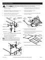
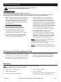
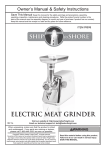
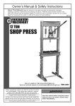
Table of Contents
Safetye��������������������������������������������������������� 3
Specifications.............................................. 4
Assembly���������������������������������������������������� 5
Operationa���������������������������������������������������� 6
Maintenancei����������������������������������������������� 7
Parts Lists and Assembly Diagrams............ 8
Warranty..................................................... 12
WARNING SYMBOLS AND DEFINITIONS
This is the safety alert symbol. It is used to alert you to potential personal injury hazards.
Obey all safety messages that follow this symbol to avoid possible injury or death.
Indicates a hazardous situation which, if not avoided,
will result in death or serious injury.
Indicates a hazardous situation which, if not avoided,
could result in death or serious injury.
Indicates a hazardous situation which, if not avoided,
could result in minor or moderate injury.
Addresses practices not related to personal injury.
Page 2
For technical questions, please call 1-800-444-3353.
Item 69904
IMPORTANT SAFETY INSTRUCTIONS
FAILURE TO HEED THESE INSTRUCTIONS MAY RESULT IN
PERSONAL INJURY AND/OR PROPERTY DAMAGE.
1. Study, understand, and follow all instructions
before operating this device.
2. Do not exceed 1000 lb. rated capacity.
3. Use only on hard, level surfaces.
4. Center load on lift platform.
5. Immediately after lifting, ensure lift mechanical
load holding means is engaged.
6. Secure load with appropriate restraint device.
7. Do not adjust safety valve.
8. Wear ANSI-approved safety goggles and
heavy‑duty work gloves during use.
9. Keep clear of load while lifting and lowering.
10. Lower load slowly.
11. Do not use for aircraft purposes.
18. Store idle lifts out of the reach of children
and do not allow persons unfamiliar with
the lift or these instructions to operate it.
Lifts are dangerous in the hands of untrained users.
19. Have your lift serviced by a qualified
repair person using only identical
replacement parts. This will ensure that
the safety of the lift is maintained.
20. Maintain labels and nameplates on the lift. These
carry important information. If unreadable or missing,
contact Harbor Freight Tools for a replacement.
21. Read lifting requirements in service
manual of the motorcycle being lifted.
22. Industrial applications must
follow OSHA requirements.
23. Do not allow anyone on the lift or the
motorcycle/ATV while on the lift.
12. Apply parking brake and chock tires
before lifting vehicle.
24. Raise Casters off the ground to
prevent movement before loading,
unloading, raising, or lowering.
13. Inspect before every use;
do not use if parts are loose or damaged.
25. Before lowering, remove all tools
and equipment from under lift.
14. Do not lift motorcycle with rear tire on ramp.
26. WARNING: The brass components of
this product contain lead, a chemical
known to the State of California to cause
birth defects (or other reproductive harm).
(California Health & Safety code § 25249.5, et seq.)
15. Keep work area clean and well lit.
Cluttered or dark areas invite accidents.
16. Keep children and bystanders away
while operating. Distractions can
cause you to lose control.
17. Stay alert. Watch what you are doing, and use
common sense when operating. Do not use while
tired or under the influence of drugs, alcohol,
or medication. A moment of inattention while
operating may result in serious personal injury.
27. Only use this lift to raise a motorcycle or an
ATV to perform maintenance. Do not attempt to
transport or relocate motorcycle/ATV while on the Lift.
28. The warnings, cautions, and instructions
discussed in this instruction manual cannot
cover all possible conditions and situations
that may occur. It must be understood by the
operator that common sense and caution are
factors which cannot be built into this product,
but must be supplied by the operator.
SAVE THESE INSTRUCTIONS.
Item 69904
For technical questions, please call 1-800-444-3353.
Page 3
Specifications
Max. Load Capacity
1000 lb.
Max. Lift Height
33"
Min. Lift Height
8-1⁄8"
Ram Travel
Platform Dimensions
Page 4
4-1⁄4"
86-1⁄2" L x 26-1⁄2" W
For technical questions, please call 1-800-444-3353.
Item 69904
Assembly Instructions
Read the ENTIRE IMPORTANT SAFETY INSTRUCTIONS section at the beginning of this manual
including all text under subheadings therein before set up or use of this product.
1. Raise the front of the Frame Asm. (14)
and put it on blocks.
6. Attach the Stop Plate (41) to the Platform (36)
using Bolts (42), Washers (33), and Nuts (43).
2. Assemble the Casters (11) to the Frame Asm. (14)
using Bolts (10), Washers (9), and Nuts (8).
7. Attach the Foot Pedal (15) to the
Pump Input Shaft (18).
3. Thread the Adjustment Screws (13) into the
Frame Asm. (14) and attach their bases.
8. Attach the Release Pedal (16) to the valve shaft,
as shown in Figure C.
4. Lower the front of the Frame Asm. (14) off the blocks.
Adjustment
Screw (13)
Foot
Pedal (15)
Pump Input
Shaft (18)
valve
shaft
Frame
Asm. (14)
Nut (8)
Release
Pedal (16)
Washer (9)
Figure C: Pedal Assembly
9. Use the Access Panel (35) to cover
the large hole in the Platform (36).
Caster (11)
base
Bolt (10)
Figure A: Caster and Adjusting Screw Assembly
10. Attach the Ramp (34) to the back of the Platform (36),
inserting both pins under the Ramp
into the holes in the Platform.
Ramp (34)
5. Attach the Vise Base (40) to the front
of the Platform (36) using Bolts (42),
Washers (33), and Nuts (43).
Access
Panel (35)
Note: Location of Vise Base (40) in relation to the
Stop Plate (41) is adjustable by means of removing
fasteners 42, 33, & 43. Tighten Nuts and Bolts only
after determining the proper tire mounting position.
42
Vise
Base (40)
Platform (36)
Figure D: Ramp and Access Panel Assembly
42
42
42
33
Stop
Plate
43
43
(41)
Figure B: Vise Base and Stop Plate Assembly
33
Item 69904
33
43
For technical questions, please call 1-800-444-3353.
Page 5
Operating Instructions
Read the ENTIRE IMPORTANT SAFETY INFORMATION section at the beginning of this manual
including all text under subheadings therein before set up or use of this product.
Before First Use
1. Check and fill oil as needed. See Checking and
Filling Hydraulic Fluid instructions on page 7.
2. Bleed the Lift Jack according to the
Bleeding instructions on page 7.
3. Test the Lift several times for proper operation
before attempting to lift a load. If, after bleeding
twice, the Lift still does not appear to be working
properly, do not use the Lift until it has been
repaired by a qualified service technician.
Lifting
1. Position the lift on a flat, level, hard surface
able to support at least 1350 lb.
4. Clamp the front wheel of the motorcycle into
the Vise to prevent movement of the wheel.
2. Turn the Lifting Screws clockwise to evenly raise
the Casters off the ground and limit movement.
Note: When properly set, front tire of motorcycle
should rest against Stop Plate with the axle centered
over the Front Wheel Vise Assembly. If not, slide
Stop Plate and/or re-position wheel Vise Base.
Locking
Bar
5. Once the Stop Plate is adjusted against the
motorcycle tire, tighten the Bolts that hold it in place.
Lifting
Screw
6. Secure the motorcycle to the lift using tie-down
straps (not included). See motorcycle’s owner
manual for locations of strap attachments.
7. Pump the Foot Pedal repeatedly to raise the lift.
Caster
Figure E: Lifting Screw and Locking Bar
3. With the Access Panel in place, roll the motorcycle
onto the lift. Kick the center stand of the
motorcycle down to stabilize it on the Platform.
8. When the platform has been raised to
the working height, pass the Locking Bar
through the holes in the Rear Lifting Arm so
the lift cannot be accidentally lowered.
9. Gently press Release Pedal to lower the platform to
rest the load on Locking Bar and not on the lift jack.
Lowering
1. Remove all tools, parts, etc. from under the vehicle.
2. Slightly raise the platform to free the Locking Bar.
3. Remove the Locking Bar, then slowly press
the Release Pedal to ease down the unit.
NOTE: The speed of lowering is controlled
by the Release Pedal. Operate this Pedal
slowly in a controlled and safe manner.
4. After lowering, open the Vise and
remove the motorcycle from the lift.
5. Turn the Lifting Screws counterclockwise
to lower the lift onto the Casters.
6. Store in a safe, dry location out of reach of children.
Small ATV Application
1. The Lift can be used to support small ATV’s
under certain conditions. A small ATV can be
rolled onto the Lift if the wheel width of the ATV
falls within the 26‑3/4" width of the Lift’s platform.
Never attempt to ride an ATV onto the platform.
The Lift should not be used to support
an ATV unless all 4 tires of the ATV can
completely rest on the platform.
Page 6
2. Use at least 2 wheel chocks (one for a front
ATV wheel and one for a back ATV wheel) to
prevent movement of the ATV while it is being
worked on. Wheel chocks sold separately.
3. Before lifting, secure the ATV to the Lift
using tie down straps (not included).
For technical questions, please call 1-800-444-3353.
Item 69904
Maintenance and Servicing
Procedures not specifically explained in this manual must
be performed only by a qualified technician.
TO PREVENT SERIOUS INJURY FROM TOOL FAILURE:
Do not use damaged equipment. If abnormal noise or vibration occurs, have the problem corrected
before further use. Lock the lift with the Locking Bar before servicing in the raised position.
1. Before each use, inspect the general condition of
the Lift. Check for broken, cracked, or bent parts,
loose or missing parts, and any condition that
may affect the proper operation of the product.
If a problem occurs, have the problem corrected
before further use.
Do not use damaged equipment.
2. If the Lift appears not to be working
properly, follow Bleeding instructions.
3. The mechanical parts of the Lift, such as
the pedal lift and release shafts should be
occasionally lubricated with heavy oil or grease.
4. Protect the Lift Cylinder from dirt or grit when
in the raised position. If it becomes dirty, wipe
it off with a clean cloth before lowering.
5. Maintain and store the Lift in a reasonably
protected environment. Do not expose to rain
or excess moisture. Protect from salt water or
other corrosive materials. If it becomes dirty or
contaminated, clean it promptly with clean water or
a suitable detergent. If using a pressure washer,
be aware that you may remove some paint from
the outer surface. Never spray a pressure washer
at the seal areas near the pistons or valves.
Lubricate external moving parts after cleaning.
6. If the lift slowly lowers on its own, it may
have damaged seals or insufficient oil.
First check the oil level. If the level is OK, take
the lift to a qualified service technician for seal
replacement. Damaged seals may be caused by
overloading, or exposure to harmful conditions
or inappropriate use of a pressure washer.
NOTE: If the lift can be raised to its highest position,
it indicates that there is enough oil.
If the lift slowly lowers from this position, it indicates
that the problem is likely with the seals.
NOTE: Do not tamper with the check valves. Any
repairs should be performed by a qualified technician.
Checking and Filling Hydraulic Fluid
1. Lower the lift completely. Remove the Access Panel
and the Oil Plug on the side of the Jack underneath.
2. The oil level should be even with the bottom of the
filler plug hole. You should be able to see the oil.
3. If the oil level is low, add SAE Hydraulic Jack
fluid only. Avoid mixing different brands of oils.
Do not use any other fluid or brake fluid.
Bleeding
Note: If the Lift appears not to be working properly, it may be necessary
to bleed trapped air from its hydraulic system.
1. Check oil level. Replace plug.
4. Let up on Release Pedal.
2. Depress Release Pedal.
5. Pump Foot Pedal.
If the motorcycle lift does not elevate smoothly or
Foot Pedal feels “spongy”, repeat steps 2 - 5.
3. Pump the Foot Pedal several times.
Item 69904
For technical questions, please call 1-800-444-3353.
Page 7
Parts Lists and Assembly Diagrams
PLEASE READ THE FOLLOWING CAREFULLY
THE MANUFACTURER AND/OR DISTRIBUTOR HAS PROVIDED THE PARTS LIST AND ASSEMBLY DIAGRAM
IN THIS MANUAL AS A REFERENCE TOOL ONLY. NEITHER THE MANUFACTURER OR DISTRIBUTOR
MAKES ANY REPRESENTATION OR WARRANTY OF ANY KIND TO THE BUYER THAT HE OR SHE IS
QUALIFIED TO MAKE ANY REPAIRS TO THE PRODUCT, OR THAT HE OR SHE IS QUALIFIED TO REPLACE
ANY PARTS OF THE PRODUCT. IN FACT, THE MANUFACTURER AND/OR DISTRIBUTOR EXPRESSLY
STATES THAT ALL REPAIRS AND PARTS REPLACEMENTS SHOULD BE UNDERTAKEN BY CERTIFIED AND
LICENSED TECHNICIANS, AND NOT BY THE BUYER. THE BUYER ASSUMES ALL RISK AND LIABILITY
ARISING OUT OF HIS OR HER REPAIRS TO THE ORIGINAL PRODUCT OR REPLACEMENT PARTS
THERETO, OR ARISING OUT OF HIS OR HER INSTALLATION OF REPLACEMENT PARTS THERETO.
Frame Parts List
Part
1
2
3
4
5
6
7
8
9
10
11
12
13
14
15
16
17
18
19
20
21
22
23
24
Page 8
Description
Pin
Washer
Front Wheel
Bolt M12x60
Liner Tube
Bolt M8x25
Plate
Nut M6
Ø6 Washer
Bolt M6x16
Caster
“U” Bolt
Adjustment Screw
Frame Asm.
Foot Pedal
Release Pedal
Nut M16
Pump Input Shaft
Bolt M16x85
Ø16 Washer
Ø16 Spring Washer
Bolt M8x30
Spring
Release Valve Spindle
Qty
2
22
2
8
4
2
1
8
8
8
2
2
2
1
1
1
3
1
1
1
1
1
1
1
Part
25
26
27
28
29
30
31
32
33
34
35
36
37
38
39
40
41
42
43
44
45
46
47
Description
Pump
T-connector
Bolt M10x20
Pin
Locking Bar
Front Lifting Arm
Rear Lifting Arm
Handle
Ø10 Washer
Ramp
Access Panel
Platform
Nut M12
Vise Jaw
Bolt
Vise Base
Stop Plate
Bolt M10x25
Nut M10
Nut M8
Link
Stud Bolt
Spring
For technical questions, please call 1-800-444-3353.
Qty
1
1
2
1
1
1
1
1
4
1
1
1
8
1
1
1
1
4
12
4
2
1
1
Item 69904
Frame Assembly Diagram
35
34
36
2
4
30
39
32
4
38
27
40
28
45
27
2
12
42
43
26
41
24
43
23
33
33
25
20
21
17
31
29
43
43
16
37
19
17
22
1
2
2
46
45
44
3
47
15
18
2
5
14
4
2
4
5
7
6
8
10
13
2
4
5
11
10
Record Product’s Serial Number Here:
Note: If product has no serial number, record month and year of purchase instead.
Note: Some parts are listed and shown for illustration purposes only,
and are not available individually as replacement parts.
Item 69904
For technical questions, please call 1-800-444-3353.
Page 9
Parts List A - Pump
Part
1A
2A
3A
4A
5A
6A
7A
8A
9A
10A
11A
12A
13A
14A
15A
16A
Page 10
Description
Top Nut
O-ring
Nylon Ring
Reservoir
Oil Plug
Nylon Ring
Piston Rod
Nylon Ring
O-ring
Cylinder
Nylon Ring
Steel Ball
Steel Ball
Ring
Adjustable Spring
Adjustable Screw
Qty
1
1
1
1
1
1
1
1
1
1
1
3
1
1
1
1
Part
17A
18A
19A
20A
21A
22A
23A
24A
25A
26A
27A
28A
29A
30A
31A
Description
O-ring
Screw
Set Nut
R-pin
Cover
Short Axle
Long Axle
Pump Piston
Sealing Ring
O-ring
Regulating Plug
Copper Washer
Release Valve
Ring
Base
For technical questions, please call 1-800-444-3353.
Qty
1
1
1
2
1
1
1
1
1
1
1
1
1
1
1
Item 69904
Assembly Diagram A - Pump
1A
2A
7A
19A
3A
20A
21A
22A
20A
24A
4A
8A
5A
25A
23A
9A
26A
27A
6A
10A
28A
12A
11A
12A
13A
14A
15A
16A
17A
18A
29A
30A
12A
31A
Item 69904
For technical questions, please call 1-800-444-3353.
Page 11
Limited 90 Day Warranty
Harbor Freight Tools Co. makes every effort to assure that its products meet high quality and durability standards,
and warrants to the original purchaser that this product is free from defects in materials and workmanship for the
period of 90 days from the date of purchase. This warranty does not apply to damage due directly or indirectly,
to misuse, abuse, negligence or accidents, repairs or alterations outside our facilities, criminal activity, improper
installation, normal wear and tear, or to lack of maintenance. We shall in no event be liable for death, injuries
to persons or property, or for incidental, contingent, special or consequential damages arising from the use of
our product. Some states do not allow the exclusion or limitation of incidental or consequential damages, so the
above limitation of exclusion may not apply to you. THIS WARRANTY IS EXPRESSLY IN LIEU OF ALL OTHER
WARRANTIES, EXPRESS OR IMPLIED, INCLUDING THE WARRANTIES OF MERCHANTABILITY AND FITNESS.
To take advantage of this warranty, the product or part must be returned to us with transportation charges
prepaid. Proof of purchase date and an explanation of the complaint must accompany the merchandise.
If our inspection verifies the defect, we will either repair or replace the product at our election or we may
elect to refund the purchase price if we cannot readily and quickly provide you with a replacement. We will
return repaired products at our expense, but if we determine there is no defect, or that the defect resulted
from causes not within the scope of our warranty, then you must bear the cost of returning the product.
This warranty gives you specific legal rights and you may also have other rights which vary from state to state.
3491 Mission Oaks Blvd. • PO Box 6009 • Camarillo, CA 93011 • (800) 444-3353