1
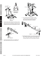
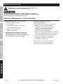
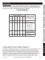
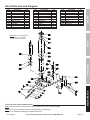
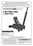
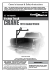
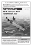
Table of Contents
SAFETY
Safety.......................................................... 3
Specifications.............................................. 4
Setup........................................................... 4
Operation..................................................... 7
Maintenance................................................ 8
Parts Lists and Diagrams........................... 10
Warranty..................................................... 12
WARNING SYMBOLS AND DEFINITIONS
This is the safety alert symbol. It is used to alert you to potential personal injury hazards.
Obey all safety messages that follow this symbol to avoid possible injury or death.
SETUP
Indicates a hazardous situation which, if not avoided,
will result in death or serious injury.
Indicates a hazardous situation which, if not avoided,
could result in death or serious injury.
Indicates a hazardous situation which, if not avoided,
could result in minor or moderate injury.
Addresses practices not related to personal injury.
OPERATION
MAINTENANCE
Page 2
For technical questions, please call 1-888-866-5797.
Item 61858
IMPORTANT SAFETY INFORMATION
1. Study, understand, and follow all instructions
before operating this device.
14. Keep your work area clean and well lit.
Cluttered work areas invite accidents.
2. Do not exceed rated capacity.
15. Keep bystanders, children, and visitors
away while operating Engine Crane.
Distractions can cause you to lose control.
5. Use only sling or chains with a rated capacity
greater than the weight of the load being lifted.
6. Do not allow load to swing or drop
violently while lowering or moving.
7. No alterations shall be made to this product.
Do not adjust safety valve.
8. Properly extend leg extensions and secure
boom in proper setting before use.
16. Stay alert. Watch what you are doing, and use
common sense when operating a ram. Do not use
a ram while tired or under the influence of drugs,
alcohol, or medication. A moment of inattention while
operating rams may result in serious personal injury.
17. Follow instructions in the “Inspection, Maintenance,
And Cleaning” section of this manual.
Use of unauthorized parts or failure to follow
maintenance instructions may create a risk of
injury and may void any applicable warranty.
9. Follow capacities marked on boom; capacity
decreases as boom lengthens.
18. Maintain labels and nameplates on the
Engine Crane. These carry important
information. If unreadable or missing, contact
Harbor Freight Tools for a replacement.
10. Wear ANSI-approved safety goggles and
heavy-duty work gloves during use.
19. Before use, read manufacturer’s instruction
manual for the object you will lift.
11. Verify replacement ram has same rating,
mounting points and maximum length.
20. Industrial applications must follow
OSHA requirements.
12. Do not use for aircraft purposes.
21. The warnings, precautions, and instructions
discussed in this manual cannot cover all possible
conditions and situations that may occur. The
operator must understand that common sense and
caution are factors, which cannot be built into this
product, but must be supplied by the operator.
13. Inspect before every use; do not use
if parts loose or damaged.
SETUP
4. Before moving, lower the load to
the lowest possible point.
OPERATION
3. Use only on hard, level surfaces.
SAFETY
Read all safety warnings and instructions.
Failure to follow the warnings and instructions may result in serious injury.
Save all warnings and instructions for future reference.
MAINTENANCE
SAVE THESE INSTRUCTIONS.
Item 61858
For technical questions, please call 1-888-866-5797.
Page 3
Specifications
Ram Capacity
Package Contents
3 Ton
SAFETY
Boom Positions
1 Ton
3/4 Ton
1/2 Ton
1/4 Ton
Part
69-5/8"
73-3/4"
77-7/8"
82"
Meets 2005 ANSI/ASME PALD standards.
29
26
25
24
23
27
31
Box A
Description
Leg
Support
Support Post
Boom
Boom Extension
Ram
Handle
Qty
2
2
1
1
1
1
1
Part
28
Box B
Description
Base
Assembly
Hardware and
Casters
Qty
1
Lot
Assembly
Bolt Shaft Identification Chart
SETUP
Chain
Bolt
Part #20
14 x 80 mm
Frame
Bolt
Part #9
14 x 100 mm
Top Ram
Bolt
Part #16
16 x 80 mm
Bottom
Ram Bolt
Part #10
16 x 90 mm
Hinge
Bolt
Part #14
18 x 110 mm
Large
Caster Bolt
Part #1A
8 x 20 mm
Small
Caster Bolt
Part #1B
8 x 14 mm
OPERATION
MAINTENANCE
Note: Match shaft of bolt
with shapes to determine bolt
part number and function.
TO PREVENT SERIOUS INJURY AND DEATH: The correct bolts must be used during
assembly. Carefully compare bolts to Bolt Identification illustration above and the measurements shown in
the parts list and assembly diagrams near the end of this manual to make sure that the correct bolts are used
in the correct place.
For safety and ease of assembly, use two people to assemble the Shop Crane.
CAUTION: DO NOT TIGHTEN ANY BOLTS UNTIL YOU ARE FULLY FINISHED WITH ASSEMBLY.
OTHERWISE PARTS WILL NOT LINE UP PROPERLY.
Page 4
For technical questions, please call 1-888-866-5797.
Item 61858
Base
Nut
Large
Caster
Legs
Figure D
Large Caster Bolt (1B)
Figure A
1. To attach two Large Casters to the rear section of the
Base, align the four mounting holes in each Large
Caster with the four mounting holes on the underside
of each Base end. Secure in place using four Large
Caster Bolts, Washers, Lock Washers and Nuts.
4. Slide Legs into front of the Base.
Rear
Lock Pin
Base
Front
Lock Pin
Small
Caster
Washer
Lock Washer
Small Caster Bolt (1B)
Figure B
2. To attach two Small Casters to the front section
of the Base, align the four mounting holes in each
Small Caster with the four mounting holes on the
underside of each base end. Secure in place using
four Small Caster Bolts, Washers and Lock Washers.
R-Pins
SETUP
Washer
SAFETY
Base
Figure E
5. Lock Legs in place using the Lock Pins. To
insert the Lock Pins, lift up on front of Base
until holes line up. After all four Lock Pins are
inserted, insert one R-Pin through small hole at
end of each Lock Pin until it snaps into place.
Note: Make sure Lock Pins are
secure before proceeding.
OPERATION
Lock
Washer
Frame Bolt (9)
Post
Leg
Nut
Lock
Washer
Base
Large
Caster
Washers
Nuts
Washer
Figure C
3. To attach one Large Caster to the end of each Leg,
align the four mounting holes in each Large Caster
with the four mounting holes on the underside
of each Leg. Secure in place using four Large
Caster Bolts, Washers, Lock Washers and Nuts.
Item 61858
Figure F
6. Use the Frame Bolts, Washers, and Nuts to secure
the bottom of the Post to the Base.
For technical questions, please call 1-888-866-5797.
Page 5
MAINTENANCE
Large Caster Bolt (1B)
Nut
Washer
Lock Washer
SAFETY
Washer
Post
Nut
Leg
Leg
Bolt (16)
Ram
Support
Bolt
(9)
The bends of the
Supports face out
at the top and in
at the bottom as
shown above.
Post
Nut
Washer
Bolt (10)
Bolt (9)
Supports
Figure I
Nut
Bolt (9)
SETUP
Washer
Lock
Washer
Figure G
9. Use a Bottom Ram Bolt, Washer and Nut
to attach lower end of the Ram to the Post
and a Top Ram Bolt, Washer and Nut to
attach the top of the Ram to the Boom.
7. Use two Frame Bolts, Washers and Nuts to fasten
the lower ends of the Supports to the inside of the
Frame, then use one Frame Bolt, Washer and Nut
to fasten the top ends of the Supports to the Post.
R-Pin
Boom Extension
Boom Pin
Nut
Lock Washer
Washer
Boom
OPERATION
Nut
Lock Washer
Washer
Bolt
Figure H
Figure J
Chain Bolt (20)
10. Slide the Boom Extension into the Boom and use the
Bolt, Washer and Nut to secure at the desired load
rating. Use the Bolt, Washer and Nut to attach the
Hook and Chain to the end of the Boom Extension.
8. Use the Hinge Bolt, Washer, Lock Washer and
Nut to attach the Boom to the top of the Post.
MAINTENANCE
Page 6
For technical questions, please call 1-888-866-5797.
Item 61858
Operating Instructions
Read ENTIRE IMPORTANT SAFETY INFORMATION section at beginning of this manual
Note: Once Assembly is complete, tighten ALL Bolts before initial operation.
5. To raise the Boom, turn the Ram’s release valve
fully clockwise (right). Insert the Handle into the
Ram and pump (up and down) repeatedly until
the item has been lifted to the desired height.
Lifting and Lowering
SAFETY
including all text under subheadings therein before set up or use of this product.
WARNING! Fully tighten the release valve
or else the Ram may lower or may not
be able to reach the full height.
3/8 Ton Load
Folding the Frame
Figure K
1. Locate the hole on the Boom with a weight limit
higher than the weight you will be lifting.
For example: Locate the 1/2 TON
hole on the Boom for a load that is
under 1/2 Ton. See Figure K.
WARNING! Do not fold the Crane while loaded.
1. Lower the Crane all the way.
SETUP
6. To lower the Crane, SLOWLY turn the Ram’s
release valve counterclockwise (left).
2. Remove R-Pins from the Front Lock Pins. Remove
the front Lock Pins. Leave rear Lock Pins in.
3. Raise the Legs, then reinsert Front
Lock Pins and reinsert R-Pins.
IMPORTANT! Before first use, check for proper
hydraulic oil level and thoroughly test the
equipment. If it does not work properly, bleed
excess air from its hydraulic system as follows:
Boom Pin
1. Open Release Valve and lower Ram completely.
Figure L
2. Adjust the Boom Extension
so the hole farthest from the
hook-end aligns with the chosen hole on the
Boom. Secure into place by inserting the Boom
Pin through all aligned holes and securing in
place with the R-Pin. See Figure L above.
WARNING! Keep clear of the object that is being
lifted by the Engine Crane. Be aware of the possibility
of a load slipping off the Hook and Chain. An item
that falls from the Crane can cause serious injury.
3. Move the Crane so that the Hook and Chain
are directly above the item to be lifted.
2. Remove Oil Plug and fill with hydraulic
oil (sold separately) to full level.
3. Apply downward pressure to the Boom and
Pump the Ram Handle quickly several times.
4. Check the Oil Fill Hole and, if necessary, top
off the Oil Fill Hole with hydraulic oil.
5. Replace the Oil Plug and close the Release Valve.
6. Test the equipment several times for proper operation
before attempting to lift a load. If, after bleeding,
the equipment still does not appear to be working
properly, do not use the equipment until it has
been repaired by a qualified service technician.
4. Securely attach the Hook and Chain to the item.
Item 61858
OPERATION
Bleeding Instructions
For technical questions, please call 1-888-866-5797.
Page 7
MAINTENANCE
R-Pin
Maintenance and Servicing
Procedures not specifically explained in this manual must
be performed only by a qualified technician.
SAFETY
TO PREVENT SERIOUS INJURY FROM ACCIDENTAL OPERATION:
Do not use damaged equipment. If abnormal noise or vibration occurs,
have the problem corrected before further use.
Cleaning, Maintenance, and Lubrication
1. BEFORE EACH USE, inspect the general
condition of the tool. Check for:
• loose hardware,
• misalignment or binding of moving parts,
• cracked or broken parts, and
SETUP
• any other condition that may
affect its safe operation.
2. Before each use, thoroughly test the Ram
for proper operation prior to its actual use.
If the Ram appears to not be working properly,
follow Bleeding instructions on page 7.
3. Change the hydraulic oil at least
once every three years:
a. With the Ram fully lowered, remove the Oil
Filler Plug on the side of the Housing.
b. Tip the Ram to allow the old hydraulic oil
to drain out of the Housing completely,
and dispose of the old hydraulic oil in
accordance with local regulations.
c. With the Ram upright, completely fill the Housing
with a high quality hydraulic oil (not included) until
the oil just begins to run out of the Oil Fill Hole.
d. Open the valve Release Screw and pump
the Handle to bleed air from the system.
e. Reinstall the Oil Filler Plug.
4. Wipe dry with a clean cloth. Then, store the
Ram in a safe, dry location out of reach of
children and other non-authorized people.
OPERATION
MAINTENANCE
Page 8
For technical questions, please call 1-888-866-5797.
Item 61858
Troubleshooting
TO PREVENT SERIOUS INJURY: Use caution when troubleshooting malfunctioning
ram. Stay clear of supported load. Completely resolve all problems before use.
If solutions presented in Troubleshooting guide do not solve the problem, have a qualified technician inspect and
repair ram before use. After ram is repaired: Test it carefully without a load by raising and lowering it fully,
checking for proper operation, BEFORE RETURNING RAM TO OPERATION.
DO NOT USE A DAMAGED OR
MALFUNCTIONING RAM!
SAFETY
POSSIBLE SYMPTOMS
Handle
Ram will Hook
Pump
Hook
moves
not lift at lowers stroke will not up when
its weight under
feels
lift all
Ram is
capacity
load spongy the way
under
load
Check that Release Valve is
closed fully.
Bleed air from the system.
X
SETUP
X
PROBABLE SOLUTION
Oil
(Make certain that the Ram
leaking
is not supporting a load
from
while attempting a solution.)
Filler
Plug
Valves may be blocked and may
not close fully. To flush the valves:
X
X
1. Lower the Chain / Hook
and securely close the
Release Valve.
X
2. Manually lift the Chain /
Hook several inches.
3. Open the release valve and
force the Chain / Hook down
as quickly as possible.
Ram may be low on oil. Check
the oil level and refill if needed.
X
X
OPERATION
Ram may require bleeding - see
instructions on page 7.
Unit may have too much
hydraulic oil inside, check fluid
level and adjust if needed.
PLEASE READ THE FOLLOWING CAREFULLY
THE MANUFACTURER AND/OR DISTRIBUTOR HAS PROVIDED THE PARTS LIST AND ASSEMBLY DIAGRAM
IN THIS MANUAL AS A REFERENCE TOOL ONLY. NEITHER THE MANUFACTURER OR DISTRIBUTOR
MAKES ANY REPRESENTATION OR WARRANTY OF ANY KIND TO THE BUYER THAT HE OR SHE IS
QUALIFIED TO MAKE ANY REPAIRS TO THE PRODUCT, OR THAT HE OR SHE IS QUALIFIED TO REPLACE
ANY PARTS OF THE PRODUCT. IN FACT, THE MANUFACTURER AND/OR DISTRIBUTOR EXPRESSLY
STATES THAT ALL REPAIRS AND PARTS REPLACEMENTS SHOULD BE UNDERTAKEN BY CERTIFIED AND
LICENSED TECHNICIANS, AND NOT BY THE BUYER. THE BUYER ASSUMES ALL RISK AND LIABILITY
ARISING OUT OF HIS OR HER REPAIRS TO THE ORIGINAL PRODUCT OR REPLACEMENT PARTS
THERETO, OR ARISING OUT OF HIS OR HER INSTALLATION OF REPLACEMENT PARTS THERETO.
Item 61858
For technical questions, please call 1-888-866-5797.
Page 9
MAINTENANCE
X
X
Parts Lists and Diagrams
Crane Parts List and Diagram
SAFETY
Part
1a
1b
2
3
4
5
6
7
8
9
10
Description
Qty
Large Caster Bolt M8 x 20 16
Small Caster Bolt M8 x 14
8
Washer M8
24
Lock Washer M8
24
Nut M8
16
Lock Pin 110mm
4
Washer M14
6
Lock Washer M14
6
Nut M14
6
Frame Bolt M14 x 100
5
Bottom Ram Bolt M16 x 90 1
Part
11
12
13
14
15
16
17
18
19
20
21
Description
Washer M16
Lock Washer M16
Nut M16
Hinge Bolt M18 x 110
Boom Pin 95mm
Top Ram Bolt M16 x 80
Nut M18
Lock Washer M18
Washer M18
Chain Bolt M14 x 80
Large Caster
24
32
SETUP
17
18
19
14
23
7
26
25
27
20
6
OPERATION
11
28
8
21
4
8
12
9
3
Qty
2
1
1
1
2
1
1
2
1
1
5
30
9
2
7
8
13
31
10
1a
Description
Small Caster
Boom Extension
Boom
Support Post
Support Brace
Ram
Base
Leg
Chain/Hook Assembly
Handle
R-Pin
13
6
26
Part
22
23
24
25
26
27
28
29
30
31
32
11
15
16
9
12
Qty
2
2
2
1
1
1
1
1
1
1
4
5
7
6
6
7
8
32
22
29
2
1b 3
MAINTENANCE
29
1a
21
2
4
3
Note: Some parts are listed and shown for illustration purposes only,
and are not available individually as replacement parts.
Page 10
For technical questions, please call 1-888-866-5797.
Item 61858
Part
1A
2A
3A
4A
5A
6A
7A
8A
9A
10A
11A
Description
Screw
O-Ring
Spring
Ball Cup
Steel Ball
Screw Cover
Release Valve
Rectangle Seal Ring
Steel Ball
Base
Pin
Qty
1
1
1
1
1
1
1
1
1
1
2
Part
13A
14A
15A
16A
17A
18A
19A
20A
21A
22A
23A
Description
Pin Shaft
Connecting Bar
Handle Sleeve
Steel Ball
Washer
O-Ring
Shield Ring
Pump Core
Washer
Hydraulic Cylinder
Pump Body
Qty
2
1
1
2
1
1
1
1
1
1
1
Part
24A
25A
26A
27A
28A
29A
30A
31A
32A
Description
Seal Ring
Oil Tank
Oil Plug
Rectangle Seal Ring
O-Ring
Top Nut
O-ring
Bowl Washer
Piston Rod
Qty
1
1
1
1
1
1
1
1
1
SAFETY
Ram Parts List and Diagram
MAINTENANCE
OPERATION
SETUP
Note: When re-ordering parts
from this list, use the part
number with the “A” suffix.
Record Product’s Serial Number Here:
Note: If product has no serial number, record month and year of purchase instead.
Note: Some parts are listed and shown for illustration purposes only,
and are not available individually as replacement parts.
Item 61858
For technical questions, please call 1-888-866-5797.
Page 11
Limited 90 Day Warranty
Harbor Freight Tools Co. makes every effort to assure that its products meet high quality and durability standards,
and warrants to the original purchaser that this product is free from defects in materials and workmanship for the
period of 90 days from the date of purchase. This warranty does not apply to damage due directly or indirectly,
to misuse, abuse, negligence or accidents, repairs or alterations outside our facilities, criminal activity, improper
installation, normal wear and tear, or to lack of maintenance. We shall in no event be liable for death, injuries
to persons or property, or for incidental, contingent, special or consequential damages arising from the use of
our product. Some states do not allow the exclusion or limitation of incidental or consequential damages, so the
above limitation of exclusion may not apply to you. THIS WARRANTY IS EXPRESSLY IN LIEU OF ALL OTHER
WARRANTIES, EXPRESS OR IMPLIED, INCLUDING THE WARRANTIES OF MERCHANTABILITY AND FITNESS.
To take advantage of this warranty, the product or part must be returned to us with transportation charges
prepaid. Proof of purchase date and an explanation of the complaint must accompany the merchandise.
If our inspection verifies the defect, we will either repair or replace the product at our election or we may
elect to refund the purchase price if we cannot readily and quickly provide you with a replacement. We will
return repaired products at our expense, but if we determine there is no defect, or that the defect resulted
from causes not within the scope of our warranty, then you must bear the cost of returning the product.
This warranty gives you specific legal rights and you may also have other rights which vary from state to state.
3491 Mission Oaks Blvd. • PO Box 6009 • Camarillo, CA 93011 • 1-888-866-5797