1
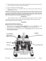
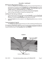
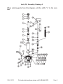
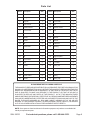
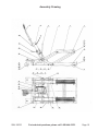
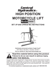
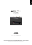
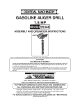
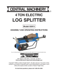
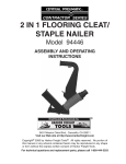
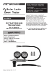
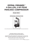
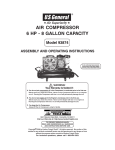
R
ATV MOTORCYCLE JACK
1500 LB. CAPACITY
93033
ASSEMBLY and OPERATING
INSTRUCTIONS
3491 Mission Oaks Blvd., Camarillo, CA 93011
Visit our Web site at http://www.harborfreight.com
Copyright© 2005 by Harbor Freight Tools®. All rights reserved. No portion of this
manual or any artwork contained herein may be reproduced in any shape or
form without the express written consent of Harbor Freight Tools .
For technical questions and replacement parts, please call 1-800-444-3353
Specifications
Construction:
Welded Steel and Cast Iron with
Hydraulic Jack
Capacity:
1500 LB S .
Overall Dimensions:
30-1/8"L x 14-1/4"W x 1-1/2 - 4"H
Saddle Frame Dimensions:
12-1/4"L x 2-3/8"W x 1-5/8"H
Ram Diameter:
1-1/8"
Lift Height Range:
4-5/8" to 14-1/4"
Jack Operation:
Handle Pump
Net Weight:
59.8 LBS.
Save This Manual
You will need the manual for the safety warnings and precautions, assembly instructions,
operating and maintenance procedures, parts list and diagram. Keep your invoice with this
manual. Write the invoice number on the inside of the front cover. Keep the manual and
invoice in a safe and dry place for future reference.
Safety Warnings and Precautions
WARNING: When using this product, basic safety precautions should always be followed to reduce the risk of personal injury and damage to equipment.
Read all instructions before using this product!
1.
Keep work area clean. Cluttered areas invite injuries.
2.
Observe work area conditions. Do not use ATV Motorcycle Jack in damp or wet
locations. Don’t expose to rain. Keep work area well lighted.
3.
Keep children away. Children must never be allowed in the work area. Do not let them
play with the ATV Motorcycle Jack.
4.
Store idle equipment. When not in use, ATV Motorcycle Jack must be stored in a dry
location to inhibit rust. Always lock up ATV Motorcycle Jack in a secure location, out of
reach of children.
5.
Use the right tool for the job. Do not attempt to force a small product or attachment to
do the work of a larger industrial product. There are certain applications for which this
product was designed. It will do the job better and more safely at the rate for which it was
intended. Do not modify this product and do not use this product for a purpose for which
it was not intended.
6.
Dress properly. Do not wear loose clothing or jewelry as they can be caught in moving
parts. Protective, electrically non-conductive clothes and non-skid footwear are
recommended when working. Wear restrictive hair covering to contain long hair.
7.
Use eye protection. Always wear ANSI approved impact safety goggles.
8.
Do not overreach. Keep proper footing and balance at all times. Do not reach over or
across running machines.
9.
Maintain tools with care. Keep ATV Motorcycle Jack clean for better and safer
performance. Follow instructions for lubricating and changing accessories. Inspect the
SKU 93033
For technical questions, please call 1-800-444-3353.
Page 2
ATV Motorcycle Jack periodically, and if damaged, have it repaired by an authorized
technician. The handle and pedals must be kept clean, dry, and free from oil and grease
at all times.
10. Stay alert. Watch what you are doing, use common sense. Do not operate the ATV
Motorcycle Jack when you are tired.
11. Check for damaged parts. Before using any product, any part that appears damaged
should be carefully checked to determine that it will operate properly and perform its
intended function. Check for alignment and binding of moving parts; any broken parts or
mounting fixtures; and any other condition that may affect proper operation. Any part that
is damaged should be properly repaired or replaced by a qualified technician. Do not
use this product if the Lifting Frame (2) doesn’t work properly.
12. Replacement parts and accessories. When servicing, use only identical replacement
parts. Use of any other parts will void the warranty. Only use accessories intended for
use with this tool.
13. Do not operate ATV Motorcycle Jack if under the influence of alcohol or drugs.
Read warning labels on prescriptions to determine if your judgment or reflexes are
impaired while taking drugs. If there is any doubt, do not operate the ATV Motorcycle
Jack
14. Maintenance. For your safety, maintenance should be performed regularly by a qualified
technician.
Additional Safety Warnings and Precautions
1.
Only operate this product on a flat, dry, level surface, capable of supporting the weight of
this product and the load.
2.
Do not attempt to lift equipment greater than the 1500 Lbs. maximum capacity.
3.
Always use good quality hydraulic oil in the Jack. Do not mix various oils, and when
filling the Jack, make sure no dirt or debris enters the hydraulic system.
4.
Once a load is elevated, do not move the ATV Motorcycle Jack. The wheels on this
product are designed to move the ATV Motorcycle Jack without a load.
5.
Always engage the Stop Bars (33 and 35) when lifting a vehicle. See FIGURE 2 on
page 5.
6.
Lower the load slowly, in a controlled fashion. Never allow the load to drop quickly.
7.
Never allow anyone to ride on this product when it is being raised, lowered, or while
holding a load.
8.
Keep fingers and hands away from the Lift Arms (4 and 6) when raising or lowering.
Keep onlookers and children a safe distance during operation.
9.
Use tie-down straps (not included) to secure the load.
10. This is a temporary lifting device only. It is not designed to support loads for extended
periods of time.
11. Before each use, check for hydraulic oil leaks; never operate the Lift if leaks are present.
SKU 93033
For technical questions, please call 1-800-444-3353.
Page 3
12. Never drop a load onto the Lift, may create for a brief instant, an excess load, which may
result in damage to the product and/or personal injury.
13. Not to be used for any aircraft purposes.
14. Always center the load on the Saddle Platform (5). Make sure the Platform does not
damage the motorcycle.
Warning: The warnings, cautions, and instructions discussed in this instruction manual
cannot cover all possible conditions and situations that may occur. It must be understood by the operator that common sense and caution are factors which cannot be
built into this product, but must be supplied by the operator.
Unpacking
When unpacking, check to make sure the parts listed on pages 7 and 9 are included.
If any parts are missing or broken, please call Harbor Freight Tools at the number on the
cover of this manual as soon as possible.
Assembly
See the Assembly Drawing on page 10.
Mounting the Jack into the Lifting Frame.
1. Being careful not to damage the Release Pedal (26), secure the Jack (36) to the Jack
Mounting Plate with two Bolts (34). See FIGURE 1 and the Assembly Drawing.
2. Place the upper end of the Jack’s ram into the Lifting Frame (2), securing it with a Pin
with Spring Attached (39).
FIGURE 1
Pin with Spring
Attached (39)
Hidden From View
Lifting Frame (2)
Spring (41)
Foot Pedal (24)
Jack (36)
Jack Mounting Plate
Release Pedal (26)
SKU 93033
For technical questions, please call 1-800-444-3353.
Page 4
Assembly (continued)
Mounting the Lifting Frame into position.
1.
Position the Stop Bar (3) and Lifting Frame (2) as shown in the Assembly Drawing, so
that the holes on the arms of both the Stop Bar (3) and Lifting Frame (2) line up with
the holes on the welded tabs on the Rear Lift Arms (4). Place Pins (28) through the
Lifting Frame (2), the Tabs, Bushings (32), and Stop Bar (3).
Please note: The Bushings fit around the Bolts and inside the Stop Bar.
2.
Secure the Bolts with Washers (29 and 30) and Spring Pin (38).
Installing the Pedal, Spring, and Handle.
1.
Loosen and remove the screw that holds in the Foot Pedal (24). Insert the Foot Pedal
(24) into the receiver of the Jack (36). Use the screw you loosened from the pedal
assembly to secure the Foot Pedal (24) into the receiver of the Jack.
2.
Insert the Handle (1) into the receptacle on the Lifting Frame (2) and secure it with the
Bolt (27).
Testing the Stop Bar (33 and 35).
The Stop Bar (33 and 35) must be locked in one of the four positions after lifting a load.
Not engaging the Stop Bar (33 and 35) may result in serious injury or death, and damage the
Lift. Before each use, check that the lower tips of the Stop Bar (33 and 35) fit behind the
notches on the both sides of the Frame Base (11). See FIGURE 2.
FIGURE 2
Lower tip of the Stop
Bar (33 and 35)
Notches on Frame Base (11)
SKU 93033
For technical questions, please call 1-800-444-3353.
Page 5
Operation
Warning!! Never work on a vehicle that is on the ATV Motorcycle Jack, or leave it unattended, if the Stop Bar (33 and 35) is not in place, or the Lock Bolts (37) are not engaged
(lifting the casters off of the ground).
Note: Keep fingers and hands away from the Lift Arms (4 and 6) when raising or lowering the
Lift. Keep onlookers and children a safe distance from the Lift during operation.
Raising the Lift.
Note: Use a second person to assist, if needed.
1. Use the Handle (1) to roll this product and position it next to the load you wish to lift. To
lower the lift so it will fit under the load, gently depress the Release Pedal (26).
Note: Check the load manual for recommended lifting points.
2. Once positioned under the load at the correct lifting points, turn the Lock Bolts (37) until
they contact the ground and lift the Swivel Casters (20) slightly off of the ground, to keep the
lift from rolling.
3. Use tie-down straps (not included) to secure the load. Repeatedly depress the Foot
Pedal (24) slowly, to raise the Saddle Platform (5). When the lift makes contact with the load,
make sure the load sits evenly on the two Saddle Platform (5) before raising the load off of the
ground. If the load is not evenly distributed on the Saddle Platform (5) and it not secured in
place with tie-down straps, it may fall from the Saddle Platform (5), resulting in possible personal injury and property damage.
4. Continue to raise the lift until you reach the desired height. Disengage the Stop Bar (3) from
the spring. You must lock the lift at one of the four locking positions with the Stop Bar (3). See
FIGURE 2.
5. This is a lifting device only. It is not designed to support loads for extended periods of
time. Do not work directly under the ATV lift.
Lowering the ATV Motorcycle Jack.
Note: Remove all tools from under the lift before lowering.
1. Depress the Foot Pedal (24) slowly to raise the lift enough to disengage the Stop Bar (3).
Lift it up and attach it to the spring.
2. Make sure everyone is clear and slowly depress the Release Pedal (26) to lower the lift.
NOTE: The Rear Pedal is designed with a Safety Valve, so it needs to be pressed down
only part way to lower the load. Once the load is on the ground, remove the tie-down straps
(not included). When the lift is clear of the load, turn the Lock Bolts (37) until they are clear of
the ground, allowing the Swivel Casters (20) to firmly contact the ground. Roll the ATV Motorcycle Jack clear of the load.
Maintenance
1. Keep your ATV Motorcycle Jack dry, protecting it from wet, corrosive environments.
2. Periodically lubricate the Jack’s moving parts.
3. Periodically check that all of the Jack’s hardware is securely fastened.
If the Jack does not work to full capacity, you may have air in the hydraulic system.
SKU 93033
For technical questions, please call 1-800-444-3353.
Page 6
Maintenance (continued)
Bleeding and filling the Jack with hydraulic oil.
1. Place the Lift on a flat, level, solid surface.
2. If just filling the Jack, open the Oil Filler Plug (10a) and check the oil. Fill to the top of the
Oil Reservoir (9a) with a high quality hydraulic oil if necessary.
3. If bleeding, with the Oil Filler Plug (10a) removed, use one foot to step on and keep the
Release Pedal (26) down, while you quickly pump the Foot Pedal (24) ten times. This will
bring all the air out of the system. Continue pumping until no more air bubbles appear. Fill to the
top of the Oil Reservoir (9a) with a high quality hydraulic oil if necessary. Repeat if necessary.
4. Replace the Oil Filler Plug (10a) .
5. Test the Jack. Make sure it is functioning properly before attempting to lift another load.
Pump the Foot Pedal (24) up and down several times, and test the Release Pedal (26) to
make sure it is working properly; if not, repeat the above process. If the lift continues to function improperly, have a qualified service technician check the product.
Jack (36) Parts List A
When ordering parts from this list, add the suffix “a” to the number.
Part No.
1a
2a
3a
4a
5a
6a
7a
8a
9a
10a
11a
12a
13a
14a
15a
16a
17a
18a
19a
20a
SKU 93033
Description
Ram Cap
Ram 0-ring
Top Sealing Gasket
Ram Assembly
Ram Gasket
0-ring
Cylinder
Lower Sealing Gasket
Oil Reservoir
Oil Filler Plug
Pedal Release Valve
Pin
Release Valve Rod
0-ring
Release Valve Pin
Base
Split Cotter Pin
Pin
Steel Ball
Spring Plunger
Qty.
1
1
2
1
1
1
1
1
1
1
1
1
1
1
1
1
4
3
1
1
Part No.
21a
22a
23a
24a
25a
26a
27a
28a
29a
30a
31a
32a
33a
34a
35a
36a
37a
38a
39a
40a
41a
Description
Spring
Screw
0-ring
Screw
Ball
Spring Plunger
Spring
Screw
Washer
Screw
Lower Sealing Gasket
Washer
Lower Spring Retainer
Pump Cylinder
0-ring
Seal
Piston Rod
Link
Handle Socket
Top Spring Retainer
Spring
For technical questions, please call 1-800-444-3353.
Qty.
1
1
1
1
3
1
1
1
1
1
1
1
1
1
1
1
1
1
1
1
1
Page 7
Jack (36) Assembly Drawing A
When ordering parts from this diagram, add the suffix “a” to the number.
SKU 93033
For technical questions, please call 1-800-444-3353.
Page 8
Parts List
Part #
Description
QTY.
Part #
Description
QTY.
1
Handle
1
22
Washer
2
2
Lifting Frame
1
23
Nut
2
3
Stop Bar
1
24
F oot P edal
1
4
Rear Lift Arm
1
25
Nut
2
5
Saddle Platform
1
26
Release Pedal
1
6
Front Lift Arm
1
27
Bolt
2
7
Bolt
4
28
Pi n
2
8
Washer
4
29
Washer
2
9
Washer
4
30
Washer
2
10
Nut
4
31
Cotter Pin
2
11
Frame Base
1
32
Bushing
2
12
Bolt
4
33
Left Stop Bar
1
13
Washer
4
34
Bolt
2
14
Nut
4
35
Right Stop Bar
1
15
Front Castor
2
36
Ja ck
1
16
Bolt
2
37
Lock Bolt
2
17
Washer
2
38
Spring Pin
1
18
Washer
2
39
Pin with Spring Attached
1
19
Nut
2
40
Axle
1
20
Swivel Castor
2
41
Spring
1
21
Washer
2
42
Spring Clip
1
PLEASE READ THE FOLLOWING CAREFULLY
THE MANUFACTURER AND/OR DISTRIBUTOR HAS PROVIDED THE PARTS DIAGRAM IN THIS
MANUAL AS A REFERENCE TOOL ONLY. NEITHER THE MANUFACTURER NOR DISTRIBUTOR
MAKES ANY REPRESENTATION OR WARRANTY OF ANY KIND TO THE BUYER THAT HE OR
SHE IS QUALIFIED TO MAKE ANY REPAIRS TO THE PRODUCT OR THAT HE OR SHE IS
QUALIFIED TO REPLACE ANY PARTS OF THE PRODUCT. IN FACT, THE MANUFACTURER
AND/OR DISTRIBUTOR EXPRESSLY STATES THAT ALL REPAIRS AND PARTS REPLACEMENTS
SHOULD BE UNDERTAKEN BY CERTIFIED AND LICENSED TECHNICIANS AND NOT BY THE
BUYER. THE BUYER ASSUMES ALL RISK AND LIABILITY ARISING OUT OF HIS OR HER
REPAIRS TO THE ORIGINAL PRODUCT OR REPLACEMENT PARTS THERETO, OR ARISING
OUT OF HIS OR HER INSTALLATION OF REPLACEMENT PARTS THERETO.
NOTE: Some parts are listed and shown for illustration purposes only and are not available individually as replacement parts.
SKU 93033
For technical questions, please call 1-800-444-3353.
Page 9
Assembly Drawing
42
SKU 93033
For technical questions, please call 1-800-444-3353.
Page 10