1
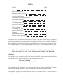
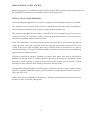
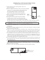
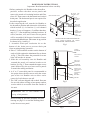
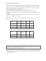
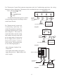
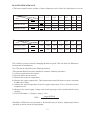
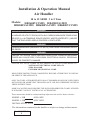
Installation & Operation Manual
Air Handler
10 to 12 SEER 3 to 5 Tons
Models: HB3600VC1M25 HB4200VA1M25
HB4800VA1M25 HB6000VA1M25 HB6000VC1M25
WARNING
WHEN THIS APPLIANCE IS INSTALLED IN AN ENCLOSED AREA, SUCH AS
A GARAGE OR UTILITY ROOM, WITH ANY CARBON MONOXIDE PRODUCING
DEVICES (i.e. AUTOMOBILE, SPACE HEATER, WATER HEATER,ETC.) INSURE
THAT THE ENCLOSED AREA IS PROPERLY VENTILATED.
WARNING
CARBON MONOXIDE (REFERED TO AS CO) CAN CAUSE PERSONAL INJURY
OR DEATH
WARNING
FAILURE TO FOLLOW THESE INSTRUCTIONS, LOCAL CODES OR NATIONAL
CODES MAY CAUSE FIRE, EXPLOSION, ELECTRICAL SHOCK, PERSONAL
INJURY OR PROPERTY DAMAGE.
FOLLOW ALL LOCAL CODES. IN THE ABSENCE OF LOCAL CODES REFER TO :
NATIONAL ELECTRICAL CODE NFPA 70
NFPA 90A & 90B
UNIFORM MECHANICAL CODE
READ THESE INSTRUCTIONS COMPLETELY BEFORE ATTEMPTING TO INSTALL
OR SERVICE THIS APPLIANCE.
ONLY FACTORY AUTHORIZED KITS OR ACCESSORIES SHOULD BE USED WHEN
INSTALLING OR MODIFYING THIS APPLIANCE, UNLESS OTHERWISE NOTED IN
THESE INSTRUCTIONS.
SOME LOCALITIES MAY REQUIRE THE INSTALLER/SERVICER TO BE LICENSED.
IF IN DOUBT CONTACT YOUR LOCAL AUTHORITIES.
These instructions should be retained and kept adjacent to the unit for future reference.
MODEL # HB
00VA1M25
MODEL # HB
00VC1M25
INSTALLATION DATE
The information contained in this booklet is subject to change without notice.
No. 0010575351
E
INDEX
TOPIC
PAGE
General
Physical dimensions
Replacement Parts Source
Installation Requirements
Air Flow Orientation
Horizontal Left-Hand Instructions
Downflow Instructions
Refrigerant Tubing
Condensate Removal
Electrical Connections
Thermostat Wiring
Orifice Change
Circulating Air Duct
Blower Performance
Start-up
Regular Maintenance
Model Number Explanation
1
2
3
3
4
5
6
7
7
8
9
11
11
12
13
13
14
The United States Environmental Protection Agency (EPA) has issued various regulations
regarding the introduction and disposal of refrigerants introduced into this unit.Failure to follow
these regulations may harm the environment and can lead to the imposition of substantial fines.
These regulations may vary due to the passage of new laws, it is recommended that any work
on this unit be done so by a certified technician. Should questions arise contact the local EPA
office.
THIS APPLIANCE IS NOT APPROVED FOR OUTDOOR INSTALLATION
THIS APPLIANCE IS NOT TO BE USED AS A CONSTRUCTION HEATER
GENERAL
This appliance was designed certified and must be installed in accordance with published
codes.In the absence of local codes please refer to the following codes:
NFPA 90A NFPA 90B
National Electrical Code NFPA 70
Uniform Mechanical Code
Prior to shipment, this appliance was tested and inspected for damage at the factory.Unpack
carefully and if damage is found, report it immediately to the transportation company.
This appliance is approved for installation in alcoves, basements, attics or crawlway, and is
designed for connection to air distribution ductwork.
2
PHYSICAL DIMENSIONS
B
D
0.8"
[2.1cm]
12.2"
[31 cm]
E
C
PLASTIC BREAKER COVER
A
5.1"
[13 cm]
PRIMARY & SECONDARY
CONDENSATE DRAINSHORIZONTAL 3/4" NPT
2"
[5.08 cm]
2"
[5.08 cm]
TYPICAL
SUCTION LINE
LIQUID LINE
F
G
1.1"
[2.9 cm]
K
5"
[12.7 cm]
2.4"
[ 6 cm]
1.2"
[ 3 cm]
J
INLET
RIGHT SIDE VIEW
H
INLET
FRONT VIEW
PRIMARY & SECONDARY
CONDENSATE DRAINSUPFLOW 3/4" NPT-FEMALE
For: HB3600VC1M25
A
B
C
D
E
F
G
H
J
K
53.3
22.1
23.5
25.2
9.1
8.3
4.7
22.2
19.8
3.6
[135.5cm] [56.1cm] [59.8cm] [64.0cm] [23cm] [21.2cm] [12cm] [56.5cm] [50.4cm] [9.05cm]
For: HB42-6000VA1M25 HB6000VC1M25
A
B
C
D
E
F
G
H
J
K
59.4
22.1
23.5
25.2
9.1
8.3
4.7
22.2
19.8
3.6
[151cm] [56.1cm] [59.8cm] [64.0cm] [23cm] [21.2cm] [12cm] [56.5cm] [50.4cm] [9.05cm]
3
1"
[2.54cm]
REPLACEMENT PARTS SOURCE
Replacement parts are available through local distributors.When ordering replacement parts, give
the COMPLETE model and serial numbers shown on the rating plate.
INSTALLATION REQUIREMENTS
Before installing this appliance insure that it is properly sized and adequate power is available.
This appliance can be installed in the vertical or right horizontal position without modification.
The horizontal left and downflow positions require product modification.
This product is designed for zero inch (0") clearance; however, adequate access for service or
replacement must be considered without removing permanent structure. This unit can be
installed on a platform when deemed necessary.
In an attic installation a secondary drain pan must be provided by the installer and placed
under the entire unit with a separate drain line properly sloped and terminated in an area
visible to the owner. This secondary drain pan is required in the event that there is a leak or
main drain blockage. Closed cell insulation should be applied to the drain lines in unconditioned
spaces where sweating may occur.
Appliances installed in garages, warehouses or other areas where they may be subjected to
mechanical damage must be suitably guarded against such damage by installing behind
protective barriers, being elevated or located out of the normal path of vehicles. When
installed on a base, the base must also be protected by similar means.
Heating and cooling equipment located in garages, which may generate a glow, spark or flame
capable of igniting flammable vapors, must be installed with the ignition source at least 18"
above the floor level.
When more than one appliance is installed in a building, permanently identify the unit as to
the area or space serviced by that applice.
4
AIR FLOW ORIENTATION
*Horizontal Right Discharge
Tube and Drain conn. front
Downflow discharge
(with plastic vertical
pan only) (see page 7)
Horizontal Left Discharge
Tube and Drain conn. front
(see page 6)
Important:
Remove the horizontal pan when
unit is installed in unconditioned
i.e. (Garage, Attic ) application,
or downflow applications, and
install insulation kit on vertical
( donut shape ) drain pan.
*Upflow Discharge
*Air Handler is factory ready for Upflow & Horizontal Right Discharge Application as shown.
5
HORIZONTAL LEFT-HAND INSTRUCTIONS
Important: Read instructions below carefully.
1) With Airhandler in the vertical position, remove all
three access panels.
2) Remove J-shape metal bracket. Slide out from the Airhandler
cavity the "A" coil pan assembly with horizontal drain
pan on the right side. Remove oval gasket from
horizontal pan drain and also remove the plastic
drain cover from the lower left access panel. Fig. 1.
Plastic
3) Relocate horizontal pan on the left-hand side of the
Drain
oval
cover
"A" coil assembly.
gasket
4) Knockouts are located within the drain assemblies.
Carefully remove only the correct knockouts using
Fig.1
a hammer and screw driver for each application, making
sure the primary and secondary drains are open and clear of burrs and debris. Remove
secondary drain knockout only if this drain is required in this particular installation.
WARNING: If incorrect knockouts are removed, flooding will occur.
5) Reinstall in the Airhandler, the "A" coil pan assembly with the horizontal drain pan on the
left-hand side.
Note: Push the assembly completely to the rear of the cavity and assure it slips into channel
bracket at the rear of the cavity.
6) Replace the J-shape metal bracket or brackets on the vertical drain pan and place the
plastic oval gasket on horizontal drain pan. Reinstall access panels and flowrator making
sure not to over torque screws. Snap in the drain cover on the right lower service panel.
7) The Airhandler can now be placed in its left horizontal position as shown in Fig.2. The
Airhandler must be leveled and then pitched 1/4" toward drain side. Important: Drain pan
must be tested for proper drainage by pouring water into the pan. Traps must be installed
on the primary drain and on the secondary drain if used.
8) In all cooling applications, a secondary drain pan must be provided by the installer and
placed under the entire unit with a separate drain line properly sloped and terminated in an
area visible to the user.
9) WARNING: The "A" coil contains 150 p.s.i.g. of air pressure.
Before setting up flowrator assembly for field brazing see page 12 or read the Warning
label on the lower access panel.
10) Failure to follow this installation requirements will cancel product warranty.
Air flow
Secondary Knockout
Primary Knockout
Fig.2
6
DOWNFLOW INSTRUCTIONS
Important: Read instructions below carefully
1.Before putting the Air Handler in the downflow
position, remove the three access panels and
remove the metal coil retaining bracket and filter
close off. Then remove the horizontal and vertical
drain pans. The horizontal pan is not required for
downfolw application
2.After removing the coil, turn the Air Handler to
the downflow position and relocate the (8) brackets
which include (1) tie bracket (1) rear channel
bracket, (2) zee coil supports, (2) stiffener brackets,
and (2) 3" 2 flat insulation retaining brackets. In
effect, brackets, coil, and 2 lower access panels
will be assembled 180 degrees from their former
position and shifted down with return in up position
as shown in fig.1 and fig.2.
3. Assemble drain pan insulation kit to the
bottom of the drain pan to prevent drain pan
from sweating during operation.
4. Place 3" flat insulation retainer on the bottom of
each coil slab against the aluminum fins as shown
in Fig.3. This will reduce the potential for water
blow-off into the air stream.
5. Slide the coil assembly into Air Handler and
reattach the metal coil retainer bracket to tie
bracket. See Fig.2. Then reattach the upper access
panel followed by the two lower access panels
to match the tubing and drains.
6. A 4" to 3" removable panel is recommended at
the point where the duct meets with the return
part of the Air Handler unit to allow easier
removal of coils that are too tall.
7. The "AD" coils are shipped with a check flowrator
for use with either cooling or heat pump outdoor
section which is accessible from the outside of
the unit.
RETURN AIR
SIDE OF UNIT
AIR HANDLER UNIT
REAR
CHANNELL
BRACKET
ZEE COIL
SUPPORT
BRACKET
COIL
RETAINING
BRACKET
TIE
BRACKET
NOTE: THE FIL TER PROVISION IS
NOT APPLICABLE IN THIS
DOWNFLOW APPLICATION
Fig.1
TOP OF
WRAPPER
INSULATION
JACKET
ZEE COIL
SUPPORT
WRAPPER
STIFFENER
DRAIN PAN
INSULATION
DPI KIT
(HATCHED
AREA)
BLOWER
MOTOR
Fig.2
WARNING: The "A" coil contains 150
p.s.i.g. of air pressure
Before setting up flowrator assembly for field
brazing see page 12 or read the Warning label
on the lower access panel.
3" FLAT
INSULATION
RETAINER (both
sides)
Fig.3
7
REFRIGERANT TUBING
Refrigerant tubing should be installed as to avoid undue stress. They must be supported or
routed to avoid strain or vibration. To avoid damage that can be caused by condensate,
insulate the suction tube with a closed cell insulation with the seams sealed. The insulation
should terminate at the tubing entrance to the air handler. Do not reduce the recommended
tubing size.
CONDENSATE REMOVAL
THIS APPLIANCE EMPLOYS A DRAW-THROUGH COIL, THEREFORE A
TRAP MUST BE INSTALLED IN THE DRAIN LINE(S) TO ALLOW FOR
PROPER CONDENSATE DISPOSAL.
The condensate trap must not be the "running" type, or "R" type. A "P " trap is required.
The total workable height of this trap, in inches, must exceed the total negative pressure,
in inches of water, as measured in the return duct.
DRAIN
CONNECTION
UNIT
2" MINIMUM
FLEXIBLE
TUBING-HOSE
OR PIPE
3" MINIMUM
A POSITIVE
LIQUID SEAL IS
REQUIRED
The condensate drain line must be at least 3/4 NPT, for each unit. Precautions must be
used not to over tighten the adapter at the drain pan connection, this precaution will
prevent damage to the plastic drain pan. A joint compound should be used to prevent
leakage and act as a lubricant.
When using copper tubing as a condensate line adequate caution muat be taken to prevent
damage to the plastic drain pan during the soldering process. All condensate drain lines
and drain traps should be adequately insulated.
The unit and the auxiliary drain pan must be adequately elevated to insure proper drainage.
Use of a condensate removal pump is permitted when necessary.This condensate pump
should have provisions for shutting off the control voltage should a blocked drain occur. A
trap must be installed between the unit and the condensate pump. Important: The evaporator
coil is coated with oils that will dissolve Styrofoam and certain types of plastics. Therefore
a removal pump or float switch must not contain any of these materials.
NOTE: AFTER INSTALLATION AND POSITIONING THE UNIT , THE DRAIN
PAN BEING USED SHOULD BE TESTED BY FILLING IT WITH WATER TO
ENSURE PROPER DRAINAGE AND CHECK FOR LEAKS.
8
ELECTRICAL CONNECTIONS
The required electrical power supply information is located on the series and rating plate
on the exterior of the unit. Wiring selection must be in accordance with local codes, or in
absence of local code, the National Electrical Code. A disconnect means should be installed
within sight of the unit, when required by code.
Copper wire is recommended for all electrical connections.
When an optional heat kit is installed refer to the electrical requirements in that kit.
The wiring diagram included in the heat kit must be placed over the wiring diagram on the
air handler.
All pertinent information, such as the rating plate, included in the optional heat kit must be
applied to the Air Handler as indicated.
The use of copper connections are recommended inside the control box (see UL 1995,
section 37.9).
Min.
Blower
Max.
Ampacity Over-current Motor
208/230 208/230
FLA
HB4200VA1M25 -------15/15
2.2
Model
No.
Blower
Motor
H.P.
1/2
HB4800VA1M25 --------
15/15
2.2
1/2
HB6000VA1M25 --------
15/15
4.0
3/4
Model
No.
Min.
Blower
Max.
running Over-current Motor
Ampacity 208/230
FLA
208/230
Blower
Motor
H.P.
HB3600VC1M25 --------
15/15
2.3
1/3
HB6000VC1M25 --------
15/15
4.0
3/4
WARNING
A MEANS OF STRAIN RELIEF MUST BE INSTALLED TO THIS APPLIANCE AT
THE ELECTRICAL SERVICE ENTRANCE.
When an optional electric heat kit is installed refer to the electrical requirements for that
kit. The ampacity and overcurrent protection shown above is only for "HB" air handlers
installed without a heat kit.
9
THERMOSTAT WIRING
For Thermostat Control Environment-temperature and Air Conditioning open/stop, the wiring
diagram as shown diagram 1. Thermostat can be mechanical type or programmable type.
Note: Thermostat C : COM.
TERMOSTAT
R : AC24V
C
O
Y
G
R
Y : COMPRESSOR
G : FAN
O : 4 -WAY VALUE
TO INDOOR
For detailed Thermostat, please connect FAN RELAY
OR
YL
RD
BL
CONTROL
corresponding terminal according to above
BL
24V
COM
control specification.
O
Y C R
TO OUTDOOR UNIT R,C,Y,O TRANSFORMER
For Thermostat only control Air
Conditioning open/stop, hot
control Environment temperature,
can adopt different power switch
show diagram 2. This mode is
control the indoor unit & heat
pump outdoor unit at the same
time no air supply mode. If need
select the air supply mode, switch
can adopt multi-connect switch
or select switch. The detailed
infor see the following diagram
3.
Above diagram: Outdoor Unit
Connection
Left: Indoor and Outdoor unit power
supply Respectively Right: Indoor unit
power supply.
Diagram 1
RUN SWITCH
MODE SWITCH
Open for heating
Close for cooling
TO INDOOR
FAN RELAY
CONTROL
RD
RD
BL
BL
24V
O
COM
Y C R
TO OUTDOOR UNIT R,C,Y,O
TRANSFORMER
Diagram 2
SELECT SWITCH
1
OFF
2
FAN ONLY
3
E. HEAT
4
HEAT PUMP
5
COOLING
6
TO FAN RELAY
CONTROL
YL
BL
RD
24V
BL
COM
O Y C R
TO OUTDOOR UNIT R,C,Y,O
Diagram 3
10
TRANSFORMER
For Thermostat Control Environment-temperature and Air Conditioning open/stop, the wiring
diagram as shown diagram 4. Thermostat can be mechanical type or programmable type.
Note: Thermostat C: COM.
TERMOSTAT
R : AC24V
C
Y
G
R
Y : COMPRESSOR
G : FAN
TO FAN
For detailed Thermostat, please connect
RELAY
RD
RD
corresponding terminal according to above
BL
CONTROL
BL
control specification.
24V
COM
C Y
TO OUTDOOR UNIT C,Y
For Thermostat only control Air
Conditioning open/stop, hot
control Environment temperature,
can adopt different power switch
show diagram 5. This mode is
control the indoor unit & cooling
only outdoor unit at the same time
no air supply mode. If need select
the air supply mode, switch can
adopt multi-connect switch or
select switch. The detailed infor
see the following diagram 6.
TRANSFORMER
Diagram 4
SWITCH
TO FAN
RELAY
CONTROL
RD
RD
BL
BL
24V
COM
C Y
TO OUTDOOR UNIT C,Y
TRANSFORMER
Diagram 5
Above diagram: Outdoor Unit
Connection
Left: Indoor and Outdoor unit power
supply Respectively Right: Indoor unit
power supply.
1
2
SELECT SWITCH
3
4
5
6
TO FAN RELAY
CONTROL
BL
RD
RD
24V
BL
COM
C Y
TO OUTDOOR UNIT C,Y TRANSFORMER
Diagram 6
11
ORIFICE CHANGE
The restrictor (orifice) included in this unit match the comparable capacity of the outdoor
unit. If the indoor unit is greater in capacity than the outdoor condenser, the orifice must
be changed to match the outdoor unit capacity. The restrictor (orifice) should be replaced
before any tubing connections are made.
THE CAPACITY OF THE OUTDOOR UNIT SHOULD NEVER EXCEED THE
CAPACITY OF THE INDOOR UNIT.
To replace the restrictor (orifice), follow the steps below:
WARNING
THIS COIL IS SHIPPED UNDER PRESSURE.
FOLLOW THESE INSTRUCTIONS TO PREVENT INJURY:
1) Loosen the 13/16 nut 1TURN ONLY. No pressure loss indicates possible leak.
2) Remove the nut and discard the seal cap.
3) Remove the check piston to verify it is correct. See piston kit chart in instructions.
4) Use a tube cutter to remove the spin closure on the suction line.
5) Remove the tailpiece clamped to the exterior.
6) Slide the 13/16 nut into position. Braze tailpiece to the liquid tube.
7) Insert the suction line into the connection, slide the insulation and the rubber grommet at
least 18" away from the braze joint.
8) AFTER THE TAILPIECE HAS COOLED, position the white Teflon seal and hand
tighten the nut.
9) Torque the 13/16 nut to 10-30 ft/lbs. or tighten 1/6 turn.
10) Replace suction line grommet and insulation.
SUCTION LINE
SEAL CAP
WITH SPIN
CLOSURE
13/16 NUT
TAIL PIECE
WHITE TEFLON SEAL
PISTON
RUBBER
GROMMET
CIRCULATING AIR DUCT
Air duct systems should be designed and installed as per local and/or national code.Refer
to NFPA 90A & 90B and the National Environmental Systems Contractors Association Manual "K".
The use of flexible duct connectors is recommended to minimize the possibility of noise
transmission. These connectors must conform to U.L. standards.
Supply air ducts must be insulated and return ducts must be insulated when passing
through an unconditioned space. When passing through an unconditoned space it may be
necessary to install a vapor barrier to the exterior of the ducts to prevent condensation.
Seams of all supply ducts must be sealed to prevent leakage and return ducts sealed
airtight to prevent infiltration.
The supply plenum should be the dimensions specified by the factory.
12
BLOWER PERFORMANCE
CFM versus Static Pressure (inches of water column dry coil w/ filter) 4% reduction for wet coil.
Static Pressure
Model
CFM
HB4200VA1M25
HB4800VA1M25
High
Middle
0.15
0.2
0.25
0.3
0.35
0.4
0.5
1449
1411
1373
1335
1297
1259
1221
1449
1701
1411
1656
1373
1611
1335
1566
1297
1518
1259
1470
1221
2063
2008
1953
1898
1841
1784
0.15
0.2
0.25
0.3
0.35
0.4
0.5
1276
1244
1213
1184
1157
1127
1097
2063
2008
1953
1898
1841
1784
HB6000VA1M25
Static Pressure
Model
HB3600VC1M25
HB6000VC1M25
CFM
The air delivery can be varied by changing the blower speeds. This can allow for differences
encountered in installations.
The CFM can be checked by the following method;
(The optional Heat Kit must be installed to continue with this procedure.)
1) All access panels must be in place.
2) Start the unit in the heat mode.
3) Measure the return air temperature.
4) Measure the supply temperature. This measurement should be done in various locations
to obtain an average.
5) Subtract the return temperature from the supply temperature. This is referred to as the
temperature rise.
6) Measure the actual supply voltage and actual amperage at the terminal block/circuit
breaker.
7) The BTUH output = (Voltage x Amps x 3.41)
output (BTUH)
CFM =
1.08 X temperature rise
Should the CFM need to be increased or decreased it may be done by adjusting the blower
speed tap as shown on the wiring diagram.
13
START-UP
Prior to initial start-up insure that all electrical connections are properly sized and tightened.
All panels must be in place and secured.
Tubing should be leak free.
Unit should be elevated, trapped and pitched to allow for drainage.
Low voltage wiring is connected.
Auxiliary drain is installed, when necessary, and pitched to allow for drainage.
Drain pans and drain tubing were leak checked with water.
Retrun and supply ducts are sealed.
Unit is elevated when installed in a garage or where flammable vapors may be present.
Unit is protected from vehicular or other physical damage.
Return air is not to be obtained from any areas where there may be objectionable odors,
flammable vapors or products of combustion such as carbon monoxide (CO) which may
cause serious personal injury or death.
REGULAR MAINTENANCE
WARNING
DISCONNECT ALL POWER SUPPLIES BEFORE PERFORMING ANY SERVICE.
The only item to be maintained on a regular basis by the user is to insure that the circulating
air filter(s) is cleaned or replaced. It is recommended that a return air filter grille be
installed.
A certified service technician should perform other services.
14