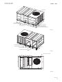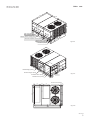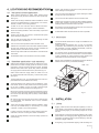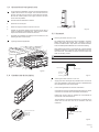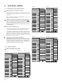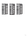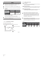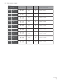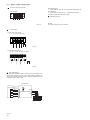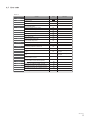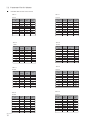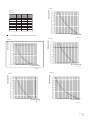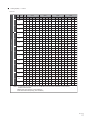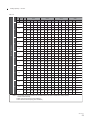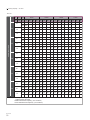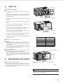
1
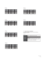
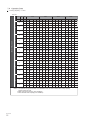
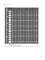
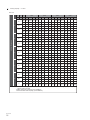
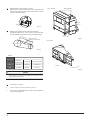
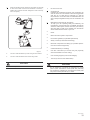
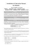
USER’S & INSTALLATION
MANUAL
RC060RTRGA
RC070RTRGA
RC080RTRGA
RC100RTRGA
RC120RTRGA
RC150RTRGA
RC180RTRGA
RC200RTRGA
RC250RTRGA
System Air Conditioner
(Cooling Only)
CONTENTS
PAGE
WARNING
ACCESSORIES.........................................................1
GENNERAL INFORMATION..........................................1
DIMENSIONAL DATA.................................................2
LOCATIONS AND RECOMMENDATIONS........................7
INSTALLATION
...............................................................7
ELECTRICAL WIRING
.....................................................10
SPECIFICATION
............................................................16
START-UP
.................................................................31
MAINTENANCE AND UPKEEP
.............................................31
Tab.1-1
Qty
Manual
1
Drain outlet
1
Snap ring
1
Drain pipe
1
KJR-12B Wire controller
Ask your dealer for improvement, repair, and
maintenance.
Incomplete improvement, repair, and maintenance may
result in a water leakage, electric shock, and fire.
In order to avoid electric shock, fire or injury, or if you
detect any abnormality such as smell of fire, turn off the
power supply and call your dealer for instructions.
Never replace a fuse with that of wrong rated current or
other wires when a fuse blows out.
Use of wire or copper wire may cause the unit to break down
or cause a fire.
1. ACCESSORIES
Name of accessories
Ask your dealer for installation of the air conditioner.
Incomplete installation performed by yourself may result in a
water leakage, electric shock, and fire.
Shape
1
2. GENERAL INFORMATION
Warnings and Cautions appear at appropriate locations
throughout this manual.
Read these carefully.
WARNING: Indicates a potentially hazardous situation
which, if not avoided, could result in death or serious injury.
CAUTION: Indicates a potentially hazardous situation
which, if not avoided, may result in minor or moderate injury.
It may also be used to alert against unsafe practices and
where property-damage-only accidents could occur.
CAUTION
Read this entire manual before beginning installation
procedures.
Bodily injury can result from high voltage electrical
components, fast moving fans. For protection from these
inherent hazards during installation and servicing, the
electrical supply must be disconnected.
If operating checks must be performed with the unit
operating, it is the technicians responsibility to recognize
these hazards and proceed safely.
Do not insert fingers, rods or other objects into the air
inlet or outlet.
When the fan is rotating at high speed, it will cause injury.
Never use a flammable spray such as hair spray,
lacqueror paint near the unit.
It may cause a fire.
Never inspect or service the unit by yourself.
Ask a qualified service person to perform this work.
Do not dispose this product as unsorted municipal
waste.Collection of such waste separately for special
treatment is necessary.
Keep far away from high-frequency equipment.
Keep away from the following places:
A place where it is full of oil gas; places where salty air
surrounding(near the coast); a place where is caustic gas(the
sulfide in hotspring). Location in the folling places may cause
malfunction or shorten the life span of the manchine.
In the cace of extremely strong wind, please prevent the
air from flowing backwards into the outdoor unit.
Snow canopy is necessary in sonwfall places on the
outdoor unit. Please consult the local dealer for details.
In the frequent thunderstruck place, lightning proof
actions should be taken.
To prevent refrigerant leak, contact your dealer.
When the system is installed and runs in a small room, it is
required to keep the concentration of the refrigerant, if by any
chance coming out, below the limit. Otherwise, oxygen in the
room may be affected, resulting in a serious accident.
The refrigerant in the air conditioner is safe and normally
does not leak.
If the refrigerant leaks in the room, contact with a fire of a
burner, a heater or a cooker may result in a harmful gas.
Turn off any combustible heating devices, ventilate the
room, and contact the dealer where you purchased the
unit.
Do not use the air conditioner until a service person confirms
that the portion where the refrigerant leaks is repaired.
I&O manual
1
3. DIMENSIONAL DATA
Units: mm
380-415V / 3Ph / 50Hz
6 / 7 Tons C/O Units
1223
2068
17
Condenser fan
900
Filter access door
Drain connection hole
587
maintain orifice
for air supply motor
1235
893
904
2089
Hole for control wires
Hole for power wires
Hole for other purpose
Control and comperssor access panel
317
Fig.3-1
695
723
Horizontal supply opening
Downflow supply opening
Horizontal return opening
465
Fresh air
287
357
Downflow return opening
40
103
Fig.3-2
Hole for bottom installation
300
303
439
120
8-19X14
Supply
1176
1235
835
693
Return
761
2089
904
217
100
30
83
Fig.3-3
I&O manual
2
380-415V / 3Ph / 50Hz
8 / 10 Tons C/O Units
Units: mm
1323
2149
17
Condenser fan
1002
Filter access door
Drain connection hole
594
maintain orifice
for air supply motor
1335
863
804
2165
Hole for control wires
Hole for power wires
Hole for other purpose
Control and comperssor access panel
453
Fig.3-4
628
822
Horizontal supply opening
Downflow supply opening
Horizontal return opening
485
Fresh air
290
406
Downflow return opening
60
103
Fig.3-5
Hole for bottom installation
368
344
410
110
8-19X14
Supply
1275
1335
1045
823
Return
805
2165
804
350
103
30
83
Fig.3-6
I&O manual
3
380-415V / 3Ph / 50Hz
12 / 15 Tons C/O Units
Units: mm
3
181
221
4
17
1245
13
5
131
Filter occess door
Drain connection hole
Maintain orifice for air supply motor
7 80
22 74 0
29
Control and comperssor access panel
Hole for control wires
1825
86
3 400
115
Hole for power wires
Hole for other purpose
6
12
Fig.3-7
294
531
644
Horizontal supply opening
Downfolw supply opening
5
105
313
Horizontal return opening
360
Downfolw ruturn opening
494
143
Hole for bottom installation
Fig.3-8
14-15×25
131
374
100
306
55
Fresh air
1825
1514
1115
122
81
804
213
577
125
30
1980
2164
2229
I&O manual
4
115
Fig.3-9
Units: mm
380-415V / 3Ph / 50Hz
18 / 20 Tons C/O Units
2138
2748
17
1245
135
142
Filter access door
Drain connection hole
7
53 83
Maintain orifice for air supply motor
27
124
1
105
Control and comperssor access panel
Hole for control wires
Hole for power wires
870
3
13
5 142
2157
7
46
Fig.3-10
Hole for other purpose
294
880
4
64 703
Horizontal supply opening
3
20
1031
67
3
Horizontal return opening
315
9
Downflow return opening
390
143
Hole for bottom installation
530
14-15×25
870
109
324
2157
1665
1270
678
550
55
178
185
104
Fig.3-11
Fresh air
59
142
Downflow supply opening
1241
2693
2753
1259
117
30
Fig.3-12
I&O manual
5
380-415V / 3Ph / 50Hz
25 Tons C/O Units
Units: mm
2138
2748
17
Drain connection hole
135
142
Maintain orifice for air supply motor
Maintain orifice for air supply motor
7
53 83
27
124
1
105
Control and comperssor access panel
Hole for control wires
Hole for power wires
870
3
13
42
5 1
2157
Fig.3-13
7
46
Hole for othere purpose
294
538
4
64 703
3
20
1031
65
3
Horizontal supply opening
265
Fresh air
52
3
Horizontal return opening
Fig.3-14
55
Hole for bottom installation
870
109
324
2157
678
142
14-15×25
1241
I&O manual
6
2693
2753
1259
117
30
Fig.3-15
4. LOCATIONS AND RECOMMENDATIONS
Caution must be taken at all times to avoid personal injuries
and/or damage to the equipment.
4.1 Horizontal airflow application
The unit must be mounted level for proper drainage of water
through the holes in the base pan.
When choose horizontal air supply mode, please remove
horizontal air supply panel and horizontal air return panel firstly.
See Fig.5-2
The unit must not be exposed to direct roof water runoff.
These units are design certified for outdoor installations. These
units may be installed directly on wood flooring or on Class A,
Class B, or Class C roof covering material.
Flexible duct connectors must be of a flame retardant material.
All duct work outside of the structure must be insulated and
weatherproofed in accordance with local codes.
Location of the unit must allow service clearance around it.
Clearance of the unit must be given careful consideration.
Roof flashing must be installed to seal the roof curb cavity and
must conform to local building codes.
Check the handling facilities to ensure the safety of personnel
and the unit(s).
Caution must be taken at all times to avoid Personal injuries
and/or damage to equipment.
The unit must be mounted level for proper drainage of water
through the holes in the base pan.
All fabricated outdoor ducts should be as short as possible.
4.3 Clearances
The recommended clearances for single-unit installations are
illustrated in Fig.4-1
These minimum requirements are not only an important
consideration when determining unit placement, but they are
also essential to ensure adequate serviceability, maximum
capacity, and peak operating efficiency.
The unit must not be exposed to direct roof water runoff.
Flexible duct connectors must be of a flame retardant material.
All duct work outside of the structure must be insulated and
weatherproofed in accordance with local codes.
Holes through exterior walls must be sealed in accordance with
local codes.
Any reduction of the unit clearances indicated in these illustrations may result in condenser coil starvation or the recirculation
of warm condenser air. Actual clearances which appear to be
inadequate should be reviewed with a local engineer.
All fabricated outdoor ducts should be as short as possible.
See the unit's nameplate for the absolute minimum clearance
between the unit and any combustible surface(s).
4.2 Downflow application-curb mounting
When choose vertical air supply mode, for model 6.2 to 10 ton,
please remove vertical air supply panel and vertical air return
panel firstly; and then unload air down flow panel, horizontal
deflector and air down-return panel; lastly, remount horizontal
air supply panel and horizontal air return panel. See Fig.5-3.
Units: mm
≥ 1000
≥ 1000
Overhead air
Clearance≥ 3000
When choose vertical air supply mode, for model 12.5 to 20
ton, please unload air down flow panel air down-return panel.
See Fig.5-4.
≥ 1000
The Roof Mounting Curb, or a field fabricated curb must be in
place before the unit is hoisted to the roof top.
The Roof Mounting Curb (frame) must be installed on a flat,
level section of the roof and provide a level mounting surface
for the unit. In addition, be sure to provide sufficient height
above the roof to prevent water from entering the unit.
Be sure the mounting curb spans structural members (trusses)
of the roof, thereby providing sufficient support for the weight of
the unit, the curb, the duct(s), and any factory or field installed
accessories.
Be sure the hole in the structure for the ducts is large enough
to accommodate the fabricated ducts and the insulation
surrounding them.
These units are design certified for outdoor installation. These
units may be installed directly on wood flooring or on Class
A,Class B, or Class C roof covering material.
Location of the unit must allow for service clearance around it.
Clearance of the unit must be given careful consideration.
Check the handling facilities to ensure the safety of personnel
and the unit(s).
Fig.4-1
5.
INSTALLATION
5.1 Lifting
Rigging cables should have adequate capability to resist 3
times weight of unit. Before lift, please check and ensure that
hooks are holding tightly to unit and lifting angles are no less
than 60°.
Cloth material or hard-paper should be padded in the contact
place between unit and rigging cable. Rigging cable should be
entwined a round at the hook for prevent danger by cable slip
because of weight unbalance.
During lifting, anyone forbidden lingering under the lifting unit.
I&O manual
7
Typical rooftop application with frame
Spreader bars
Fig.5-1
5.2 Rooftop-units
Horizontal
air deflector
Down-side air
supply orifice’s cover
Down-side air return
orifice’s cover
For roof top applications using a field fabricated frame and
ducts, use the following procedure:
The frame must be located and secured by bolting or welding
to the roof. Flashing is required.
The hole in the roof must be prepared in advance of installing
the unit.
Secure the ducts to the roof.
Place the unit on the frame or roof curb.
Fig.5-3
Secure the unit to the frame or roof curb.
Insulate any ductwork outside of the structure with at least two
(2) inches of insulation and then weatherproof. There must be
a weatherproof seal where the duct enters the structure.
Complete the installation according to the instructions in the
following sections of this manual.
Typical rooftop application with frame
Cover panel
of horizontal
air supply
Cover panel
of horizontal
air return
Fig.5-4
Fig.5-2
I&O manual
8
5.3 Ground level-horizontal units
For ground level installations, the unit should be positioned on
a pad in the size of the unit or larger. The unit must be level on
the pad. The pad must not come in contact with the structure.
Be sure the outdoor portion of the supply and return air ducts
are as short as possible.
≥ 40mm
Proceed with the installation as follows:
●
Place the unit on the pad.
●
Attach the supply and return air ducts to the unit.
●
Insulate any ductwork outside of the structure with at least 2
inches of insulation and weatherproof. There must be a weatherproof seal where the duct enters the structure.
●
Complete the installation according to the instructions in the
following sections of this manual.
I&O manual
Fig.5-6
5.5 Ductwork
Attaching horizontal ductwork to unit
Typical ground level application
All conditioned air ductwork should be insulated to minimize
heating and cooling duct losses. Use a minimum of two (2)
inches of insulation with a vapor barrier. The outside ductwork
must be weatherproofed between the unit and the building.
When attaching ductwork to a horizontal unit, provide a flexible
watertight connection to prevent noise transmission from the
unit to the ducts. The flexible connection must be indoors and
made out of heavy canvas.
NOTE
Do not draw the canvas taut between the solid ducts.
Unit duct flance
Fig.5-5
Unit exterior
Weather proof
this seam
5.4 Condensate drain piping
Fig.5-7
Field duct
Attaching downflow ductwork to roof curb
●
Supply and return air flanges are provided on the roof curb for
easy duct installation. All ductwork must be run and attached to
the curb before the unit is set into place.
●
Follow these guidelines for ductwork construction:
Connections to the unit should be made with three-inch canvas
connectors to minimize noise and vibration transmission.
Elbows with turning vanes or splitters are recommended to
minimize air noise and resistance.
The first elbow in the ductwork leaving the unit should be no
closer than two feet from the unit, to minimize noise and
resistance.
Unit
Drain connection hole
Drain outlet
Snap ring
Drain pipe
Air proof this seam
Field duct
Fig.5-8
I&O manual
9
6.
ELECTRICAL WIRING
Tab.6-3
6.1 Protections and safety control
Minutes delay for the compressor start-up
●
●
10 Tons
Model type
C/O
Type of flow
Hor. & Dow.
Type of flow
Hor. & Dow.
Applicable
voltage
the
The reverse phase protection relay will make the compressor
not start, when the power source is incorrectly connected.
The checking of phase’ order is just carried out at the first time
of electrifying. If malfunction happens then the checking will be
going on until the order of phase is right, and the E0 will be
displayed on the board. If there is no problem in the first
checking, then it will be omitted.
High pressure and low pressure protection
The ON/OFF of high pressure and low pressure will be
installed separately around inlet pipe, and both are connected
to Main Control Board. The ON/OFF of high pressure will be
off when the pressure is higher than 425Psi. The ON/OFF of
low pressure will be off when lower than 7Psi.
6.2 Electrical data
Nominal ton
6 Tons
Nominal ton
7 Tons
Model type
C/O
Model type
C/O
Type of flow
Hor. & Dow.
Type of flow
Hor. & Dow.
Unit main
power
Applicable
voltage
VOL
380
- 415
Hz
50
Max.
418
Min.
342
STC
39
Compressor
RNC
motor
IPT
12.6
2.8
Condenser RNC
fan motor
2.0
IPT
I&O manual
IPT
1.8
0.7
VOL
380
- 415
Hz
50
Applicable Max.
voltage
418
Min.
342
STC
55
Compressor
RNC
motor
7.0
Evaporator RNC
fan motor IPT
Electric
heating
Unit main
power
IPT
Evaporator RNC
fan motor
IPT
Condenser RNC
fan motor
IPT
Electric
heating
IPT
15
8.0
3.0
1.9
2.2
0.8
380
- 415
Hz
50
Max.
418
Min.
342
STC
55
IPT
16.5
5.3
Condenser RNC
fan motor
2.2
IPT
Electric
heating
Unit main
power
2.8
0.8
Tab.6-5
380
- 415
Hz
50
418
Min.
342
STC
60
Compressor
RNC
motor
IPT
18.4
10.5
Evaporator RNC
fan motor
5.3
Condenser RNC
fan motor
2.2
IPT
IPT
Electric
heating
IPT
VOL
Applicable Max.
voltage
8.9
Evaporator RNC
fan motor IPT
2.8
0.8
IPT
Tab.6-6
12 Tons
Nominal ton
Model type
C/O
Model type
C/O
Type of flow
Hor. & Dow.
Type of flow
Hor. & Dow.
Nominal ton
Unit main
power
VOL
380
- 415
Hz
50
Max.
418
Min.
342
STC
128
Compressor
RNC
motor
Tab.6-2
Tab.6-1
VOL
Compressor
RNC
motor
Applicable
voltage
R407C 380-415V / 3Ph / 50Hz
10
Nominal ton
C/O
When switchover between cooling/heating
compressor stops automatically.
Reverse phase protection relay
●
8 Tons
Model type
Unit main
power
Compressor discharge gas temperature switch protection
When compressor discharge gas temperature
discharge gas temperature switch will be closed. At the same
time, the corresponding compressor will be shut off. The
ON/OFF signal and high-pressure protection signal should be
connected together.
●
Nominal ton
At the beginning of energizing or after the stop of the
compressor, 3-minutes delay will be taken to start the
compressor.
mode,
Tab.6-4
IPT
27.4
8.5
Condenser RNC
fan motor
3.4
Electric
heating
IPT
5.5
1.5
VOL
380
- 415
Hz
50
Applicable Max.
voltage
418
Min.
342
STC
110
Compressor
RNC
motor
13.5
Evaporator RNC
fan motor IPT
IPT
Unit main
power
15 Tons
IPT
32.1
15.3
Evaporator RNC
fan motor
8.5
Condenser RNC
fan motor
5.2
IPT
IPT
Electric
heating
IPT
5.5
1.7
Tab.6-8
Tab.6-7
Nominal ton
18 Tons
Tab.6-9
Nominal ton
20 Tons
Nominal ton
25 Tons
Model type
C/O
Model type
C/O
Model type
C/O
Type of flow
Hor. & Dow.
Type of flow
Hor. & Dow.
Type of flow
Hor.
Unit main
power
Applicable
voltage
VOL
380
- 415
Hz
50
VOL
380
- 415
Hz
50
418
Applicable Max.
418
Min.
342
Min.
342
STC
128
STC
140
Max.
Compressor
RNC
motor
IPT
Evaporator RNC
fan motor IPT
Condenser RNC
fan motor
IPT
Electric
heating
Unit main
power
IPT
38.4
voltage
Compressor
RNC
motor
18
8.5
5.5
5.2
1.7
IPT
44.2
8.5
Condenser RNC
fan motor
5.2
IPT
Electric
heating
IPT
Applicable
voltage
5.5
1.7
VOL
380
- 415
Hz
50
Max.
418
Min.
342
STC
195
Compressor
RNC
motor
20.2
Evaporator RNC
fan motor
IPT
Unit main
power
IPT
Evaporator RNC
fan motor IPT
Condenser RNC
fan motor
IPT
Electric
heating
50.2
27.2
10
7.5
6.5
3.4
IPT
I&O manual
11
6.4 Wiring provision
NOTE
These data are based on the following conditions.
Evaporator Air Input Temperature 85 F DB, 66 F WB.
Condenser Air Input Temperature 115 F DB.
The strating current is indicated for each compressor motor.
The maximum currents of the compressor can be estimated
as follows.
Tab.6-10
One compressor unit Two compressors unit
Max. current
RNC×Max. IPT*/IPT
RNC×Max. IPT*/IPT
Max. instantaneous
current
STC
STC+RNC×0.5
×Max. IPT*/IPT
Max. IPT*: Compressor power input from the performance table at
the expected maximum condition
STC,IPT,RNC: Compressor data from the above table
The data in the compressor motor column shall indicate the respective values of the refrigeration cycle.
6.3 Installation Example
Required components
The following components are required: main power fuses,
conduit coupling, and field supplied room thermostat.
Wire and fuse size selection for main power source
Wire and fuse sizes should be selected in accordance with
national and standard, taking the designed maximum current
shall be the total of the compressor maximum current,
condenser fan motor current and evaporator fan motor
current(refer to “electrical data”).
Wire size between room thermostat and unit
The wire size between the room thermostat and the unit should
be determined according to the following table, because the 24V
power source is applied to the control circuit.
Wiring length between room thermostat and unit(one way)
Minimum wire
size(mm2)
4 wires for Power supplies
unit
Earth
Fig.6-1
12
Required field wiring
Main power wiring to the unit control wiring between the control
center and the unit, and earth wiring are required in the field.
Tab.6-11
To the 4 wires from wire controller
(for C/O units) or 5 wires from wire controller
(for E/Heater+C/O units and H/P units)
Main power switch
I&O manual
Field wiring
The units are internally wired at the factory according to
generally accepted electrical technology.
10m
15m
20m
30m
40m
0.5
0.5
0.75
0.75
1.0
6.5 Main power supply
Tab.6-12
Model type
Unit main power
Main power switch
Fuse
Wires for Power supplies
6Tons
C/O
380 - 415V
3N~ 50Hz
50A
40A
3×10mm2+2×6mm2
7Tons
C/O
380 - 415V
3N~ 50Hz
50A
40A
3×10mm2+2×6mm2
8Tons
C/O
380 - 415V
3N~ 50Hz
63A
50A
3×16mm2+2×10mm2
10Tons
C/O
380 - 415V
3N~ 50Hz
63A
50A
3×16mm2+2×10mm
C/O
380 - 415V
3N~ 50Hz
75A
63A
3×16mm2+2×10mm2
C/O
380 - 415V
3N~ 50Hz
85A
75A
3×25mm2+2×10mm2
C/O
380 - 415V
3N~ 50Hz
100A
80A
3×25mm2+2×10mm2
20Tons
C/O
380 - 415V
3N~ 50Hz
100A
80A
3×25mm2+2×10mm2
25Tons
C/O
380 - 415V
3N~ 50Hz
120A
100A
3×35mm2+2×10mm2
12Tons
15Tons
18Tons
I&O manual
13
6.6 Block cable connection
To connect with wire controller
See the left figure:
1. When SW3 has been set in “ON”, please select KJR-12B
wire controller;
2. When SW3 has been set in “1”, please select the wire
controller be recommended in the below.
For C/O Units
R
G
Y
(C)
KJR-23B (For C/O)
Remark:
Two stage capacity control is optional.
Fig.6-2
Power supply
For 380-415V / 3Ph / 50Hz
6 / 7 / 8 / 10 Tons C/O Units
L1
L2 L3
N
Fig.6-3
For 380-415V / 3Ph / 50Hz
12 / 15 / 18 / 20 / 25 Tons C/O Units
L1
L2
N
L3
Fig.6-4
Dial code settings
Set the dial code SW3 of PCB in roof-top unit’s wire control box as
per the wire controller you are in using. After settings, please shut
off the power supply and then power to it again, otherwise, the new
settings function couldn’t work.
For C/O Units
KJR -1 2B
C
D
E
ON
SW3
RED
Y ELLOW
BL ACK
WH ITE
1
CN7
MAIN CONTROL BOARD
CN9
CN36
GREEN
WHITE
RED
YELLOW
A
B
5 -termi na l
Gro up
BROW N
R G Y C
TO THE WIRE CONTROLLER
I&O manual
14
XT2
6.7 Error code
Tab.6-13
Type
Content
Code
Normal
Standby
Normal
Constraint cool
on
Normal
Run
10.
Error
Compressor phase sequence
error or phase default
E0
Error
Outdoor coil sensor in sys. A error
E1
Error
Outdoor coil sensor in sys. B error
E2
Error
Indoor coil sensor in sys. A error
E5
Error
Indoor coil sensor in sys. B error
E6
Error
Indoor sensor error
E9
Error
Outdoor ambient sensor error
EA
Error
Wire controller output error
Eb
Protection
Overcurrent protection in sys.A
P0
Protection
Overcurrent protection in sys.B
P1
Protection
Overcurrent protection for indoor fan
P2
Protection
Comprehensive protection for outdoor fan
P3
Protection
Protection for Hi./Lo. pressure or exhaust temp.
in sys.A
P4
Protection
Protection for Hi./Lo. pressure or exhaust temp. in
sys.B
P5
Protection
Hi-pressure protection initiated in T2 evaporator
stops the outdoor unit fan
P6
Protection
Hi-pressure protection initiated in T2 evaporator
stops the outdoor unit fan and compressor
P7
Protection
Protection for condenser Hi-temp. in sys.A
P8
Protection
Protection for condenser Hi-temp. in sys.B
P9
Protection
Anti-freezing protection for evaporator in sys. A
Pc
Protection
Anti-freezing protection for evaporator in sys. B
Pd
Protection
Defrosting
Remarks
Comprehensive protection
in sys.A
Comprehensive protection
in sys.B
dF
I&O manual
15
7. SPECIFICATION
7.1 Physical Data
R22 380-415V / 3Ph / 50Hz
Tab.7-1
10 Tons
12 Tons
15 Tons
C/O
C/O
C/O
C/O
C/O
Hor. & Dow.
Hor. & Dow.
Hor. & Dow.
Hor. & Dow.
Hor. & Dow.
Hor. & Dow.
73400
94000
107000
127000
150000
180000
6 Tons
Model type
C/O
Type of flow
Capacity
Performance
Dimensions
Cooling capacity (Btu/h)
Heating capacity (Btu/h)(
( )
)
SEER
9.7
10.5
10.3
10.4
9.4
Length(mm)
2089
2089
2165
2165
2229
2229
Width(mm)
1235
1235
1335
1335
1825
1825
Heigth(mm)
900
900
1002
1002
1245
1245
402
406
441
443
700
710
9.9
Net weight(kg)
Refrigerant type
Flow control (
)
Compressor Quantity/Type
Rows
Outdoor coil Fins per inch
Tube diameter(in.)
Rows
Indoor coil
R22
R22
R22
Capillary
Capillary
Capillary
Capillary
2/Scroll
2/Scroll
2/Scroll
2/Scroll
2/Scroll
2/Scroll
3
3
3
3
3
3
R22
15
15
15
15
15
15
3/8
3/8
3/8
3/8
3/8
3/8
2
2
3
3
3
3
17
17
15
15
15
15
3/8
3/8
3/8
3/8
3/8
3/8
Drive type
Outdoor fan Quantity speeds
1/650
1/650
1/650
1/650
2/650
2/650
Propeller
Propeller
Propeller
Propeller
Propeller
Propeller
Direct
Direct
Direct
Direct
Direct
Direct
1
1
1
1
1
1
Quantity motors/power(kW)
1/0.55
1/0.55
1/0.60
1/0.60
2/0.60
2/0.60
Motor RPM
940±10
940±10
930±30
930±30
930±30
930±30
5880
5880
7060
7060
10000
11000
1/10×10
1/10×10
1/12×12
1/12×12
1/15×15
1/15×15
FC centrifugal
FC centrifugal
FC centrifugal
FC centrifugal
FC centrifugal
FC centrifugal
Belt
Belt
Belt
Belt
Belt
Belt
Variable sheave
Variable sheave
Variable sheave
Variable sheave
Variable sheave
Variable sheave
1/1.5
1/1.5
1/1.5
1/1.5
1/5.5
1/5.5
Total nominal CFM
Quantity used/diameter(in.)
Type
Drive type
Quantity speeds
Quantity motors/power(kW)
)
R22
Capillary
Tube diameter(in.)
Quantity used/diameter(mm)
Filters (
R22
Capillary
Fins per inch
Type
Indoor fan
7 Tons
8Tons
Nominal ton
Motor RPM
1440
1440
1440
1440
1440
1440
Total nominal CFM
2500
3000
3400
5000
6000
Quantity size
recommended (mm)
(4)
529X357X12.5
(4)
529X357X12.5
(4)
566X404X12.5
4000
(4)
566X404X12.5
(2)
(2)
1015X815X12.5 1015X815X12.5
NOTE
NOTE
Cooling capacities are rated at 95 F amblent, 80 F entering dry bulb, 67 F entering wet bulb. Air capacity is net and
inculdes the effect of fan motor heat.Units are suitable for operation to ±20% of nominal CFM.
( )
Heating capacities are based on the following conditions:Indoor temperature 70 F entering dry bulb, 60 F entering dry
bulb, outdoor temperature 47 F entering dry bulb, 43 F entering dry bulb.
( )
( )
TXV is optional.
(
Optional 2” pleated filters also available.
)
I&O manual
16
Tab.7-2
Nominal ton
18 Tons
20 Tons
25 Tons
Model type
C/O
C/O
C/O
Type of flow
Hor. & Dow.
Hor. & Dow.
Hor.
210000
240000
Cooling capacity (Btu/h)(
)
Heating capacity (Btu/h)(
Performance SEER
)
Capacity
Dimensions
10.0
9.7
9.7
Length(mm)
2753
2753
2753
Width(mm)
2157
2157
2157
Heigth(mm)
1245
1245
1245
900
930
980
Net weight(kg)
Refrigerant type
R22
Flow control (
Capillary
)
Compressor Quantity/Type
Rows
Outdoor coil Fins per inch
Tube diameter(in.)
Rows
Indoor coil
2/Scroll
2/Scroll
2/Scroll
3
3
3.5
15
15
16
3/8
3/8
5/16
4
3
15
15
16
Tube diameter(in.)
3/8
3/8
5/16
Drive type
Outdoor fan Quantity speeds
Quantity motors/power(kW)
2/800
Propeller
Direct
Direct
Direct
1
1
1
2/1.1
2/1.1
2/1.5
944
910
14000
16765
1/18X18
1/18×18
1/18×18
FC centrifugal
FC centrifugal
FC centrifugal
Belt
Belt
Belt
Quantity used/diameter(in.)
Drive type
Quantity speeds
2/750
Propeller
944
Total nominal CFM
Type
2/750
Propeller
12500
Motor RPM
)
R22
Capillary
3
Type
Filters (
R22
Capillary
Fins per inch
Quantity used/diameter(mm)
Indoor fan
300000
Variable sheave
Variable sheave
Variable sheave
Quantity motors/power(kW)
1/5.5
1/5.5
1/7.5
Motor RPM
1440
1440
1440
Total nominal CFM
6800
7800
10200
Quantity size
recommended (mm)
(2)
978X956X12.5
(2)
978X956X12.5
(3)
964X640X12.5
NOTE
Cooling capacities are rated at 95 F amblent, 80 F entering dry bulb, 67 F entering wet bulb. Air capacity is net and
inculdes the effect of fan motor heat.Units are suitable for operation to ±20% of nominal CFM.
( )
Heating capacities are based on the following conditions:Indoor temperature 70 F entering dry bulb, 60 F entering dry
bulb, outdoor temperature 47 F entering dry bulb, 43 F entering dry bulb.
( )
( )
TXV is optional.
(
Optional 2” pleated filters also available.
)
I&O manual
17
7.2 Parameter For Air Volume
Parameter table for indoor unit air volume
Tab.7-3
Tab.7-7
6 Tons
12 Tons
Static pressure Air flow Brake power Fan speed
(rpm)
(Pa)
(CFM)
(kW)
0
20
40
60
75
100
120
3350
3100
2702
2585
2402
2202
2100
150
1924
2.1
2.1
2.0
2.0
2.0
1.9
1.9
1.9
956
962
971
979
982
987
993
999
I&O manual
0
20
40
60
75
100
120
6250
5850
5500
5300
5150
4900
4750
150
4550
4.1
4.0
3.9
3.8
3.7
3.6
3.5
3.4
860
870
880
890
900
910
920
930
Tab.7-4
Tab.7-8
7 Tons
15 Tons
Static pressure Air flow Brake power Fan speed
(rpm)
(Pa)
(CFM)
(kW)
Static pressure Air flow Brake power Fan speed
(rpm)
(Pa)
(CFM)
(kW)
0
20
40
60
75
100
120
3355
3235
3120
2900
2825
2350
2510
150
2355
2.5
2.4
2.3
2.2
2.1
2.0
1.9
1.9
1313
1321
1329
1335
1340
1345
1351
1357
0
20
40
60
75
100
120
6900
6700
6400
6500
6250
6000
5800
4.6
4.5
4.45
4.33
4.25
4.15
4.0
1000
1010
1020
1030
1040
1050
1060
150
5530
3.9
1070
Tab.7-5
Tab.7-9
8 Tons
18 Tons
Static pressure Air flow Brake power Fan speed
(rpm)
(Pa)
(CFM)
(kW)
18
Static pressure Air flow Brake power Fan speed
(rpm)
(Pa)
(CFM)
(kW)
0
20
40
60
75
100
120
3904
3780
3580
3422
3386
3238
3129
150
3280
2.3
2.2
2.2
2.1
2.0
1.9
1.8
1.7
1200
1215
1228
1249
1258
1267
1275
1281
Static pressure Air flow Brake power Fan speed
(rpm)
(Pa)
(CFM)
(kW)
0
20
40
60
75
100
120
8100
7750
7520
7300
7150
6850
6670
5.1
5.0
4.9
4.8
4.7
4.6
4.5
820
829
835
844
856
864
873
150
6400
4.4
885
Tab.7-6
Tab.7-10
10 Tons
20 Tons
Static pressure Air flow Brake power Fan speed
(rpm)
(Pa)
(CFM)
(kW)
Static pressure Air flow Brake power Fan speed
(rpm)
(Pa)
(CFM)
(kW)
0
20
40
60
75
100
120
4706
4529
4353
4716
4030
3873
3756
150
3588
2.5
2.4
2.3
2.2
2.1
2.0
1.9
1.9
1200
1210
1221
1235
1248
1255
1259
1265
0
20
40
60
75
100
120
150
8570
8440
8250
8150
8000
7810
7750
7600
5.6
5.5
5.4
5.3
5.2
5.1
5.0
4.9
902
906
910
914
918
920
925
928
8 Tons
Static pressure (Pa)
Tab.7-11
25 Tons
Static pressure Air flow Brake power Fan speed
(rpm)
(Pa)
(CFM)
(kW)
225
250
12450
11400
10000
10200
9900
9790
9300
300
8600
0
75
125
170
200
6.1
5.8
5.6
5.5
5.37
5.2
5.01
4.7
1000
1002
1005
250
225
200
175
150
125
1008
1010
1015
1017
100
75
50
1022
25
0
Curve diagram of static pressure, air flow volumn.
2600 2800 3000 3200 3400 3600 3800
4000
Air volume(CFM)
Fig.7-3
10 Tons
Static pressure (Pa)
Static pressure (Pa)
6 Tons
250
225
200
175
300
270
240
210
180
150
150
125
120
100
90
75
60
50
30
25
0
0
2900 3200 3500 3800 4100 4400 4700 5000
Air volume(CFM)
1765 2060 2355 2650 2945 3240 3535 3830
Air volume(CFM)
Fig.7-4
Fig.7-1
12 Tons
Static pressure (Pa)
Static pressure (Pa)
7 Tons
250
225
200
175
300
270
240
210
150
180
125
150
100
120
75
90
50
60
25
30
0
2060 2355 2650 2945 3240 3535 3830 4125
Air volume(CFM)
Fig.7-2
0
4250 4500 4750 5000 5250 5500 5750 6000 6250
Air volume(CFM)
Fig.7-5
I&O manual
19
25 Tons
Static pressure (Pa)
Static pressure (Pa)
15 Tons
300
270
240
210
180
150
120
90
60
30
0
4750 5000 5250 5500 5750 6000 6250 6500 6750 7000 7250
Air volume(CFM)
Air volume(CFM)
Fig.7-9
Fig.7-6
Static pressure (Pa)
18 Tons
300
Parameter table for outdoor unit air volume
270
NOTE
240
210
Shield parts in below tables are standard working
conditions for the unit.
180
150
120
Tab.7-12
90
6 Tons
60
Static pressure
(Pa)
Air flow
(CFM)
0
5880
0.78
900
10
5647
0.79
889
20
5411
0.80
875
30
0
5200 5500 5800 6100 6400 6700 7000 7300 7600 7900 8200
Air volume(CFM)
Fig.7-7
Brake power Fan speed
(kW)
(rpm)
20 Tons
Static pressure (Pa)
Tab.7-13
7 Tons
300
Static pressure
(Pa)
Air flow
(CFM)
240
0
5880
0.78
900
210
10
5647
0.79
889
180
20
5411
0.80
875
270
Brake power Fan speed
(kW)
(rpm)
150
120
90
60
Tab.7-14
30
8 Tons
0
7000 7150 7300 7450 7600 7750 7900 8050 8200 8350 8500
Air volume(CFM)
Fig.7-8
I&O manual
20
Static pressure
(Pa)
Air flow
(CFM)
Brake power Fan speed
(kW)
(rpm)
0
7060
0.78
935
10
6765
0.79
926
20
6471
0.80
918
Tab.7-15
Tab.7-19
10 Tons
20 Tons
Static pressure
(Pa)
Air flow
(CFM)
Brake power Fan speed
(kW)
(rpm)
0
7060
0.78
10
6765
20
6471
Static pressure
(Pa)
Air flow
(CFM)
935
0
14000
1.3×2
940
0.79
926
10
13500
1.4×2
938
0.80
918
20
13100
1.5×2
930
Tab.7-16
Tab.7-20
12 Tons
25 Tons
Static pressure
(Pa)
Air flow
(CFM)
Brake power Fan speed
(kW)
(rpm)
Static pressure
(Pa)
Air flow
(CFM)
Brake power Fan speed
(kW)
(rpm)
Brake power Fan speed
(kW)
(rpm)
0
9000
0.78×2
935
0
16765
1.7×2
910
10
8800
0.79×2
926
10
16470
1.6×2
900
20
8600
0.80×2
918
20
16176
1.5×2
890
7.3 Operating conditions
Tab.7-17
15 Tons
Static pressure
(Pa)
Air flow
(CFM)
Brake power Fan speed
(kW)
(rpm)
0
11000
0.78×2
935
10
9800
0.79×2
926
20
9600
0.80×2
918
For proper performance, run the unit under the following
temperature conditions:
Tab.7-21
Outdoor temperature: 63°F to 126°F
Room temperature: 63°F to 86°F
Cooling
operation
Caution
Room relative humidity less than 80%. If the unit
operates in excess of this figure the surface of
the unit may attract condensation.
Tab.7-18
18 Tons
Static pressure
(Pa)
Air flow
(CFM)
0
Brake power Fan speed
(kW)
(rpm)
12500
0.78×2
945
10
12000
0.79×2
938
20
11700
0.80×2
930
I&O manual
21
7.4 Capacity Data
Cooling capacity — 6 Tons
Tab.7-22
Air
Flow CFM
Ent
DB
61
85
67
73
61
Ambient Temperature
95
67
73
61
105
67
73
61
115
67
73
61
125
67
73
(F)
2100
75
80
85
2400
90
75
80
85
2600
90
75
80
85
2800
90
75
80
22
90
MBH 67.2 69.3 74.2 77.4 69.1 72.3 76.2 79.1 70.6 74.4 77.8 80.1 72.2 75.9 78.8 80.9
SHC 58.4 65.8 70.5 73.5 62.4 68.0 71.6 74.4 66.2 69.0 72.1 74.3 70.0 73.6 76.4 78.5
MBH 75.7 76.0 76.6 77.7 76.5 77.0 77.8 79.3 77.1 77.9 78.8 80.3 77.6 78.3 79.3 81.1
SHC 44.4 55.5 66.2 76.6 46.4 57.8 69.3 78.3 48.4 60.0 71.9 79.3 48.8 61.8 74.1 80.1
MBH 79.1 80.0 80.8 81.7 79.4 80.3 81.4 82.2 79.8 80.6 81.6 82.7 80.0 81.0 81.9 82.9
SHC 29.2 40.6 49.0 58.2 29.7 42.3 50.1 59.7 30.1 43.9 51.1 61.0 30.5 41.5 52.1 62.2
MBH 62.2 65.3 70.6 75.1 64.1 68.3 73.6 77.5 65.8 70.9 75.8 78.9 67.2 73.2 77.1 79.9
SHC 56.0 61.5 66.5 70.7 59.8 64.3 69.3 73.0 48.4 60.0 71.4 74.3 63.3 69.0 72.6 75.3
MBH 72.2 72.5 73.4 75.2 72.9 73.4 76.2 77.8 74.5 75.0 76.3 79.2 75.2 75.9 77.4 80.2
SHC 43.1 54.6 66.1 74.2 45.2 57.8 70.1 75.8 47.2 60.7 73.7 76.2 49.0 63.3 76.8 77.6
MBH 78.1 78.6 79.4 80.1 78.5 79.1 79.9 80.8 78.9 79.4 80.3 81.2 79.1 80.1 80.8 81.6
SHC 28.2 39.6 50.8 59.8 28.7 41.2 51.0 61.6 29.1 42.9 52.3 63.3 29.5 42.2 53.4 64.8
MBH 57.0 61.0 66.4 71.8 58.8 63.9 69.7 74.6 60.5 66.5 72.4 76.6 62.5 68.8 74.2 77.9
SHC 53.5 56.7 61.8 66.8 57.4 59.4 64.8 69.4 56.3 61.8 67.3 71.2 58.1 64.0 69.0 72.4
MBH 66.8 67.4 68.5 72.1 68.4 69.0 70.4 74.6 69.6 70.3 72.6 76.9 70.6 71.5 74.3 78.2
SHC 40.7 52.2 63.8 69.7 43.0 55.7 68.7 73.5 45.2 59.1 71.6 75.3 47.3 62.4 73.4 75.9
MBH 75.9 76.2 76.4 77.0 76.5 76.9 77.3 78.0 77.0 77.4 78.0 78.8 77.3 78.0 78.5 79.4
SHC 27.0 38.3 49.6 59.9 27.4 40.1 51.5 62.8 27.9 41.5 53.3 65.3 28.4 42.6 55.0 67.5
MBH 51.7 56.6 62.1 67.7 53.6 59.3 64.2 70.9 55.7 61.7 67.8 73.2 57.6 63.9 70.0 74.9
SHC 51.0 54.8 60.2 65.6 51.9 57.5 63.2 68.7 54.0 59.8 65.7 70.9 55.8 61.9 67.8 72.6
MBH 51.0 56.8 62.4 67.9 62.2 63.0 66.2 71.2 63.4 64.5 67.9 73.5 64.5 65.8 70.1 75.3
SHC 38.2 49.6 61.4 66.8 40.5 53.2 63.4 69.7 42.7 56.7 65.2 70.6 44.8 60.1 67.3 72.3
MBH 72.1 72.3 72.7 72.9 73.1 73.5 73.8 74.2 73.8 74.0 74.4 75.3 74.3 74.8 75.2 76.3
SHC 25.6 37.0 48.3 59.4 26.1 38.7 51.0 63.0 26.5 40.3 53.6 66.4 27.0 42.0 55.9 69.4
MBH 45.3 47.2 49.0 50.6 46.3 48.3 50.1 51.7 46.6 48.6 50.5 52.1 47.0 48.9 51.0 53.4
SHC 43.8 35.6 27.9 21.4 45.2 37.8 28.6 22.5 44.5 38.6 29.1 23.6 46.5 39.2 29.6 24.1
MBH 50.0 50.9 51.7 52.2 51.1 52.1 52.8 53.4 51.5 52.5 53.2 53.8 51.8 52.9 53.7 55.0
SHC 44.3 36.7 28.3 21.8 32.8 41.1 49.5 50.4 33.2 42.7 50.8 52.7 35.2 45.3 50.9 53.9
MBH 53.8 54.5 55.3 56.7 55.0 55.8 56.5 57.2 55.2 56.1 56.8 57.3 56.3 57.5 58.2 59.3
SHC 45.8 37.6 29.2 22.3 46.3 38.2 31.6 24.5 47.2 38.9 32.3 25.6 48.9 39.0 33.4 25.3
Notes: 1.All capacities are gross and have not considered indoor fan heat.To obtain NET cooling capacity
subtract indoor fan heat.
2.MBH=Total Gross Capacity. (Unit:1000Btu/h)
3.SHC=Sensible Heat Capacity.(Unit:1000Btu/h)
I&O manual
85
Cooling capacity — 7 Tons
Tab.7-23
Air
Flow CFM
Ent
DB
61
85
67
73
61
Ambient Temperature
95
67
73
61
105
67
73
61
115
67
73
61
125
67
73
(F)
2700
75
80
85
3000
90
75
80
85
3300
90
75
80
85
3600
90
75
80
85
90
MBH 82.5 84.2 85.8 87.5 87.3 89.0 90.8 92.6 89.3 91.1 92.9 94.8 91.0 92.8 94.7 96.6
SHC 72.7 80.4 85.3 87.5 77.4 84.3 88.2 91.1 82.0 84.5 87.9 92.3 86.2 90.3 93.5 95.2
MBH 94.8 96.7 98.6 100.6 95.9 97.8 99.8 101.8 96.7 98.6 100.6 102.6 97.3 99.2 101.2 103.3
SHC 55.6 68.8 81.8 94.3 58.0 72.6 85.4 96.3 59.5 73.8 88.2 100.1 60.8 75.8 90.7 100.8
MBH 98.6 100.6 102.6 104.6 99.2 101.2 103.2 105.2 99.4 101.4 103.4 105.5 99.7 101.7 103.7 105.8
SHC 36.8 51.0 62.0 72.4 37.3 50.7 62.3 75.1 37.8 54.8 63.3 75.4 38.3 56.7 64.2 76.8
MBH 78.6 80.2 81.8 83.4 81.0 82.6 84.3 86.0 83.3 85.0 86.7 88.4 85.3 87.0 88.7 90.5
SHC 69.6 75.6 78.0 81.4 72.3 78.6 81.2 85.3 75.2 79.3 83.5 86.7 83.8 85.1 87.2 89.3
MBH 85.6 87.3 89.1 90.8 87.1 94.0 96.6 98.0 91.4 96.2 98.1 99.8 93.2 98.1 100.9 101.9
SHC 53.9 67.7 81.6 86.2 56.3 71.6 86.5 91.3 58.7 75.0 90.8 92.0 61.1 78.1 94.5 95.9
MBH 97.8 99.8 101.8 103.8 98.3 100.3 102.3 104.3 98.7 100.7 102.7 104.7 98.6 100.6 102.6 104.6
SHC 35.7 50.2 62.3 74.5 36.2 51.2 64.1 77.3 36.8 52.0 65.6 79.2 37.3 55.6 66.9 81.1
MBH 72.1 73.5 75.0 76.5 74.4 75.9 77.4 79.0 76.5 78.0 79.6 81.2 78.4 80.0 81.6 83.2
SHC 66.4 68.3 71.3 73.2 71.2 72.4 76.3 78.4 75.3 76.5 77.9 80.4 76.1 78.6 80.3 82.5
MBH 84.4 86.1 87.8 89.6 86.3 88.0 89.8 91.6 87.8 89.6 91.3 93.2 89.1 90.9 92.7 94.6
SHC 51.0 65.0 79.2 86.3 53.7 66.2 85.0 90.3 56.3 73.3 90.6 92.3 58.8 77.2 90.1 92.4
MBH 95.3 97.2 99.2 101.1 95.2 97.1 99.0 101.0 96.7 98.6 100.6 102.6 97.1 99.0 101.0 103.0
SHC 34.2 48.9 64.2 76.8 34.1 50.4 65.6 78.8 35.4 52.2 67.2 80.9 35.9 53.4 68.9 83.5
MBH 65.3 66.6 67.9 69.3 67.2 68.5 69.9 71.3 69.8 71.2 72.6 74.1 72.1 73.5 75.0 76.5
SHC 63.2 64.6 66.4 68.6 61.2 64.3 67.6 69.1 67.3 69.1 71.0 73.2 70.3 71.2 73.6 75.8
MBH 76.7 78.2 79.8 81.4 78.5 80.1 81.7 83.3 80.1 81.7 83.3 85.0 81.5 83.1 84.8 86.5
SHC 47.8 62.1 75.4 80.2 50.5 66.0 78.3 82.1 53.1 70.2 82.1 84.6 55.7 74.4 82.1 85.6
MBH 90.8 92.6 94.5 96.4 86.0 87.7 89.5 91.3 92.9 94.8 96.7 98.6 93.6 95.5 97.4 99.3
SHC 32.4 46.3 61.2 76.4 33.0 48.4 63.5 78.1 33.7 50.4 66.6 82.3 34.3 52.5 69.4 85.9
MBH 59.9 61.1 62.3 63.6 61.7 62.9 64.1 65.4 64.0 65.3 66.6 68.0 66.1 67.5 68.8 70.2
SHC 58.0 59.3 60.9 62.9 56.1 59.0 62.0 63.4 61.7 63.4 65.1 67.2 64.5 65.3 67.5 69.5
MBH 70.4 71.8 73.2 74.7 72.0 73.5 74.9 76.4 73.5 75.0 76.5 78.0 74.8 76.3 77.8 79.3
SHC 43.9 57.0 69.2 73.6 46.3 60.6 71.8 75.3 48.7 64.4 75.3 77.6 51.1 68.3 75.3 78.5
MBH 83.3 85.0 86.7 88.4 78.9 80.5 82.1 83.7 85.2 86.9 88.7 90.4 85.9 87.6 89.3 91.1
SHC 29.7 42.5 56.1 70.1 30.3 44.4 58.3 71.7 30.9 46.2 61.1 75.5 31.5 48.2 63.7 78.8
Notes: 1.All capacities are gross and have not considered indoor fan heat.To obtain NET cooling capacity
subtract indoor fan heat.
2.MBH=Total Gross Capacity. (Unit:1000Btu/h)
3.SHC=Sensible Heat Capacity. (Unit:1000Btu/h)
I&O manual
23
Cooling capacity — 8 Tons
Tab.7-24
Air Flow CFM
Ent DB
61
85
67
73
61
Ambient Temperature
95
67
73
61
105
67
73
61
115
67
73
61
125
67
73
(F)
2700
75
80
85
3000
90
75
80
85
3400
90
75
80
85
3700
90
75
80
85
24
90
75
80
85
90
MBH 91.6 95.5 99.3 102.4 96.5 100.7 104.5 107.8 98.6 102.8 106.7 110.2 100.7 105.1 109.2 112.5 101.5 105.6 109.2 113.6
SHC 71.4 82.1 90.1 94.9 76.8 88.1 96.6 101.7 80.8 92.8 101.7 107.1 83.2 95.6 104.5 110.3 85.2 98.1 107.3 111.9
MBH 101.4 103.2 104.7 105.6 106.7 108.6 110.2 111.4 109.0 110.9 112.5 113.7 111.4 113.2 115.0 116.3 112.2 114.3 115.9 117.2
SHC 54.1 67.9 81.7 90.6 58.1 72.8 87.7 97.3 61.2 76.6 92.3 102.6 63.2 79.8 96.3 106.4 64.7 81.0 97.5 108.4
MBH 103.2 104.8 106.4 107.7 108.6 109.5 111.2 113.5 112.4 114.1 115.8 117.1 116.1 117.3 118.5 119.8 113.6 115.1 116.8 118.3
SHC 23.9 44.5 61.6 74.9 25.8 48.3 67.9 86.1 27.2 56.3 74.6 97.8 33.1 69.2 94.7 110.6 36.1 64.3 89.3 105.8
MBH 88.5 92.3 95.8 99.0 93.1 97.1 100.8 104.2 95.1 99.2 102.9 106.3 97.2 101.4 105.2 108.7 97.9 102.2 106.1 109.5
SHC 72.6 83.2 91.7 96.3 78.2 89.8 98.6 103.7 82.4 94.6 98.1 102.1 84.8 97.3 100.9 104.3 87.0 98.1 103.8 107.3
MBH 97.8 99.6 101.0 102.3 102.7 104.8 106.3 107.4 105.1 107.0 108.5 109.7 107.4 109.4 111.0 112.1 108.3 110.2 111.8 113.0
SHC 55.2 68.7 83.4 92.4 59.2 74.3 89.4 99.8 62.4 78.1 94.1 104.5 64.2 80.5 96.8 107.8 65.9 83.2 99.8 111.4
MBH 105.1 106.3 107.5 109.1 110.7 111.8 112.9 114.1 113.2 114.6 116.3 118.7 115.1 116.3 117.6 118.9 114.1 115.3 116.7 118.1
SHC 26.4 55.2 67.8 88.9 26.1 48.9 69.8 82.3 30.8 67.2 94.3 106.7 34.3 72.1 102.7 114.3 30.1 55.3 76.4 95.6
MBH 83.7 87.5 90.8 93.8 88.1 91.9 95.4 98.5 90.1 93.8 97.4 100.6 92.0 95.9 99.7 102.8 92.7 96.7 100.3 103.6
SHC 69.7 80.0 87.7 92.3 74.7 85.8 94.1 98.5 78.7 90.4 93.5 96.5 81.0 93.0 95.7 98 6 83.2 95.5 98.2 101.5
MBH 92.6
94.2
95.8
97.1 97.4
99.1 100.5 101.7 99.5 101.2 102.7 103.8 101.7 103.5 105.0 106.1 102.5 104.3 105.7 106.9
SHC 52.8 66.1 79.5 88.4 56.6 70.8 86.1 98.3 59.6 74.7 89.9 99.8 61.5 76.8 92.6 102.8 63.0 78.9 95.2 105.6
MBH 94.5 96.1 97.8 99.4 104.1 105.6 107.2 108.6 106.9 108.3 109.7 111.2 105.9 107.2 108.4 109.8 106.3 107.5 108.9 110.2
SHC 23.3 44.7 59.8 72.6 82.3 87.1 90.6 99.8 31.2 67.4 98.6 106.8 35.2 54.8 73.2 93.6 28.9 53.8 74.6 88.5
MBH 78.3 81.6 84.7 87.6 82.3 86.1 89.6 92.3 84.1 87.7 92.1 94.0 85.9 89.7 93.0 96.1 86.6 90.4 93.8 96.7
SHC 67.2 77.1 83.5 86.6 72.0 82.7 89.1 92.0 75.8 87.1 91.0 92.7 78.1 82.7 91.0 93.1 80.1 83.4 91.8 95.7
MBH 86.5 88.1 89.3 90.6 91.0 92.6 94.0 95.4 92.9 94.6 96.0 97.1 95.0 96.7 98.1 99.2 95.7 97.5 98.9 99.9
SHC 50.9 63.7 76.7 85.2 54.5 68.7 82.3 94.6 57.4 71.9 86.6 96.2 59.1 74.0 89.2 95.3 60.7 76.0 91.5 96.5
MBH 95.1 96.4 97.8 99.8 97.8 99.3 101.4 103.6 99.9 101.3 103.4 105.2 101.1 102.6 103.9 105.7 102.5 103.7 104.8 106.2
SHC 22.5 41.8 57.7 70.5 28.3 53.2 89.1 101.6 32.1 68.4 98.9 103.6 35.7 68.9 93.4 104.3 31.1 56.3 72.4 85.2
MBH 71.2 74.2 77.0 79.6 74.8 78.3 81.5 83.9 76.5 79.7 83.7 85.5 78.1 81.5 84.5 87.4 78.7 82.2 85.3 87.9
SHC 61.1 70.1 76.8 78.5 65.5 75.2 81.0 83.6 68.9 79.2 82.7 84.3 71.0 79.6 84.5 87.4 72.8 80.2 83.3 85.9
MBH 78.6 80.1 81.2 82.4 82.7 84.2 85.5 86.7 84.5 86.0 87.3 88.3 86.4 87.9 89.2 90.2 87.0 88.6 89.9 90.8
SHC 46.3 57.9 69.7 77.5 49.5 62.5 74.8 86.0 52.2 65.4 78.7 87.5 53.7 67.3 81.1 87.2 55.2 69.1 83.2 88.8
MBH 86.5 87.6 88.9 90.7 88.9 90.3 92.2
94.2 90.8
92.1 94.0
95.6
91.9
93.3 94.5 96.1
93.2 94.3 95.3
96.5
SHC 20.5 38.0 52.5 64.1 25.7 48.4 81.0 92.4 29.2 62.2 89.9 94.2 32.5 62.6 84.9 94.8 28.3 51.2 65.8 77.5
Notes:1.All capacities are gross and have not considered indoor fan heat.To obtain NET cooling capacity
subtract indoor fan heat.
2.MBH=Total Gross Capacity. (Unit:1000Btu/h)
3.SHC=Sensible Heat Capacity. (Unit:1000Btu/h)
I&O manual
4000
Cooling capacity — 10 Tons
Tab.7-25
Air
Flow CFM
Ent
DB
61
85
67
73
61
Ambient Temperature
95
67
73
61
105
67
73
61
115
67
73
61
125
67
73
(F)
3600
75
80
85
4000
90
75
80
85
4400
90
75
80
85
4800
90
75
80
85
90
MBH 110.9 113.1 115.4 117.7 113.8 116.1 118.4 120.8 116.5 118.8 121.2 123.6 118.6 121.0 123.4 125.9
SHC 96.8
98.7 100.7 102.7 103.2 105.3 107.4 109.5 109.2 111.4 113.6 115.9 114.7 117.0 119.3 121.7
MBH 123.4 125.9 128.4 131.0 124.6 127.1 129.6 132.2 125.7 128.2 130.8 133.4 126.3 130.0 131.4 134.0
SHC 73.2
92.0 108.3 124.8 75.6 94.3 112.8 128.5 78.0
97.3 116.5 130.4 79.6
99.7 119.4 131.2
MBH 127.9 130.5 133.1 135.7 128.3 130.9 133.5 136.2 128.6 131.2 133.8 136.5 129.8 132.4 135.0 137.7
SHC 47.7 64.9 79.6 95.3 48.3 65.8 81.2 96.7 49.0 72.1 82.4 98.4 49.7 75.6 84.2 101.3
MBH 102.8 104.9 107.0 109.1 105.9 108.0 110.2 112.4 108.9 111.1 113.3 115.6 111.1 113.1 115.6 117.9
SHC 92.7
94.6
96.4
98.4 99.2 101.2 103.2 105.3 105.4 107.5 109.7 111.9 100.5 102.5 104.6 106.7
MBH 118.7 121.1 123.5 126.0 122.5 127.0 128.5 130.1 123.8 128.0 128.7 132.3 125.1 129.4 130.0 133.3
SHC 70.8
89.8 108.6 123.4 74.3
94.8 114.0 124.3 77.4
99.3 120.3 128.4 80.2 103.2 125.7 128.2
MBH 126.8 129.3 131.9 134.6 127.1 129.6 132.2 134.9 127.8 130.4 133.0 135.6 128.1 130.7 133.3 135.9
SHC 46.3
65.4
81.5 97.8
47.2
MBH 94.5
96.4
98.3 100.3 97.8
99.8 101.8 103.8 99.8 101.8 103.8 105.9 103.5 105.6 107.7 109.8
SHC 88.6
90.4
92.2 94.0
97.1 99.0 101.0 93.4
95.2
66.7 84.3 101.9 47.5
67.6
95.3
85.8 104.7 48.4
68.7 87.9 106.8
97.2 99.1 101.2 103.2 105.3 107.4
MBH 110.3 112.5 114.8 117.1 112.9 115.2 117.5 119.8 114.6 116.9 119.2 121.6 116.3 118.6 121.0 123.4
SHC 67.6
86.4 105.9 115.6 71.3
92.1 113.7 117.9 74.2 98.3 115.5 117.6 77.8 102.8 115.6 121.3
MBH 123.8 126.3 128.8 131.4 124.6 127.1 129.6 132.2 125.2 127.7 130.3 132.9 125.8 128.3 130.9 133.5
SHC 44.3 63.2
81.0 98.3
45.2 65.6
85.3 103.7 45.7 67.5
86.9 106.8 46.3
69.7 91.2 110.4
MBH 86.3 88.0 89.8 91.6 89.2 91.0 92.8 94.7 92.3 94.1 96.0 97.9 95.8 97.7 99.7 101.7
SHC 84.6 86.3 88.0 89.8 86.2 87.9 89.7 91.5 90.2 92.0 93.8 95.7 94.3 96.2 98.1 100.1
MBH 101.3 103.3 105.4 107.5 103.2 107.0 107.4 109.5 105.6 107.7 109.9 112.1 108.2 110.4 112.6 114.8
SHC 63.5
83.2 102.1 104.1 67.3
88.2 105.3 107.4 70.8
94.1 107.3 110.5
74.1 99.6 110.3 112.5
MBH 119.2 121.6 124.0 126.5 120.1 122.5 125.0 127.5 120.8 123.2 125.7 128.2 121.1 123.5 126.0 128.5
SHC 42.2
61.3
80.1 98.7 42.9
64.1
84.3 104.1 43.7 66.8
87.9 109.3 44.3
69.1 91.2 112.7
MBH 78.5 80.0 81.6 83.3 81.1 82.7 84.4 86.1 83.9 85.6 87.8 89.0 87.1 88.8 90.6 92.4
SHC 76.9 78.4 80.0 81.6 78.4 79.9 81.5 83.2 82.0 83.6 85.3 87.0 85.7 87.4 89.2 91.0
MBH 92.1
93.9 95.8
97.7 93.8 97.9
98.2
99.6
96.0 98.1 99.9 101.9 98.4 100.3 102.3 104.4
SHC 57.7 75.6 92.8 94.7 61.2 80.2 95.7 97.6 64.4 85.5 97.5 100.5 67.4 90.5 100.3 102.3
MBH 108.4 110.5 112.7 115.0 109.2 111.4 113.6 115.9 109.8 112.0 114.3 116.5 110.1 112.3 114.5 116.8
SHC 38.4 55.7 72.8 89.7 39.0 58.3 76.6 94.6 39.7 60.7 79.9 99.4 40.3 62.8 82.9 102.5
Notes:1.All capacities are gross and have not considered indoor fan heat.To obtain NET cooling capacity
subtract indoor fan heat.
2.MBH=Total Gross Capacity. (Unit:1000Btu/h)
3.SHC=Sensible Heat Capacity. (Unit:1000Btu/h)
I&O manual
25
Cooling capacity — 12 Tons
Tab.7-26
Air
Flow CFM
Ent
DB
61
85
67
73
61
Ambient Temperature
95
67
73
61
105
67
73
61
115
67
73
61
125
67
73
(F)
4500
75
80
85
5000
90
75
80
85
5500
90
75
80
85
6000
90
75
80
26
90
SHC 106.9 126.7 135.0 142.6 112.8 134.6 141.1 148.8 118.8 134.5 143.0 149.5 123.8 138.2 145.8 151.4
MBH 149.0 150.8 152.5 154.6 153.4 154.5 155.4 156.4 155.3 156.5 157.4 158.6 156.5 157.4 159.4 160.4
SHC 85.1 103.9 121.8 140.6 88.9 107.9 127.7 146.5 90.4 110.9 131.7 152.5 92.4 113.9 135.6 157.4
MBH 157.4 160.4 162.4 164.4 159.2 161.4 164.4 166.3 161.2 163.4 165.3 167.3 163.4 166.0 168.0 170.0
SHC 58.7 78.7 95.1 110.9 59.8 80.5 97.2 112.7 60.9 81.2 98.9 116.8 61.9 82.1 100.1 120.0
MBH 124.7 127.7 133.7 142.6 126.3 131.7 139.6 147.5 130.7 133.7 143.6 151.5 133.7 138.6 147.5 154.5
SHC 101.9 121.8 124.7 131.6 107.9 126.4 134.0 141.6 113.9 127.0 136.4 143.9 118.8 133.1 141.6 148.3
MBH 139.6 141.6 143.6 146.5 145.5 150.0 151.5 152.5 151.5 153.6 154.6 156.4 152.0 155.0 157.0 158.0
SHC 81.2 100.0 118.8 137.6 84.6 104.9 124.8 145.5 87.9 108.0 130.7 151.5 90.3 112.9 135.6 156.0
MBH 153.5 155.4 157.3 159.4 154.6 156.3 158.7 161.4 156.0 158.0 160.0 161.0 159.0 162.0 164.0 166.0
SHC 56.1 75.7 93.3 109.9 57.3 78.3 95.8 113.9 58.4 79.6 98.1 116.8 59.5 80.9 100.0 119.8
MBH 116.0 119.0 125.0 135.0 120.0 123.0 133.0 139.0 122.0 127.0 138.0 147.0 125.0 132.0 142.0 150.0
SHC 97.2 104.0 113.0 125.0 104.0 111.0 122.0 129.0 110.0 116.0 128.0 137.0 113.9 128.0 137.7 145.5
MBH 133.0 135.0 138.0 139.0 134.0 137.0 141.0 143.0 141.0 143.0 145.0 149.0 144.0 146.0 148.0 153.1
SHC 76.9 96.0 114.9 134.7 88.6 101.0 121.8 143.0 83.4 105.9 127.7 141.0 86.4 109.9 133.7 150.0
MBH 151.0 152.0 153.0 154.0 153.0 154.0 155.0 157.0 155.0 156.0 157.0 158.0 156.0 157.0 158.0 160.0
SHC 53.3 72.5 90.8 108.0 54.5 75.1 93.9 112.9 55.5 77.5 96.4 115.8 56.6 78.5 98.8 121.0
MBH 106.0 110.0 120.0 130.0 109.0 115.0 125.0 135.0 112.0 120.0 129.0 138.0 115.0 123.0 134.0 143.0
SHC 93.1 106.7 116.4 126.1 98.9 111.6 121.3 131.0 104.0 115.2 123.8 132.5 103.9 110.7 120.6 128.7
MBH 125.0 127.0 128.0 130.0 126.0 129.0 131.0 133.0 133.0 135.0 138.0 140.0 136.0 138.0 140.0 145.0
SHC 80.0 92.2 111.0 127.0 84.0 97.5 118.0 121.0 88.0 102.0 123.0 125.0 82.8 107.0 131.0 143.0
MBH 141.0 143.0 145.0 146.0 145.0 147.0 148.0 149.0 148.0 149.0 150.0 151.0 149.0 150.0 151.0 152.0
SHC 50.5 69.6 88.5 107.0 51.6 73.0 92.0 111.0 54.0 75.0 96.0 117.0 54.0 78.0 98.0 119.0
MBH 101.9 104.4 108.0 109.4 104.8 107.1 109.0 111.6 109.0 110.9 113.1 115.4 112.7 115.1 117.7 119.7
SHC 93.5 83.9 69.7 66.8 96.5
89.9 74.3 68.6 97.2
91.0 75.2 69.3 99.7
92.7 76.2 70.0
MBH 103.4 105.9 109.5 110.8 121.2 123.8 126.2 129.1 123.9 126.6 129.4 131.7 127.2 130.0 132.4 135.3
SHC 96.1
85.2 75.1 67.6 99.9
91.5 76.4 69.5 101.4 92.8 77.8 70.3 103.3 94.2
78.9 71.6
MBH 106.7 109.3 111.9 114.4 141.1 143.7 146.5 149.6 141.9 145.7 147.7 150.6 142.2 145.9 148.4 151.0
SHC 103.0 89.9 80.1 69.7 103.8 93.1 77.8 70.7 105.4 96.3
81.2 71.7 107.2 97.2
Notes: 1.All capacities are gross and have not considered indoor fan heat.To obtain NET cooling capacity
subtract indoor fan heat.
2.MBH=Total Gross Capacity. (Unit:1000Btu/h)
3.SHC=Sensible Heat Capacity. (Unit:1000Btu/h)
I&O manual
85
MBH 133.0 134.6 140.6 148.5 136.6 139.5 145.5 153.4 138.1 141.6 150.5 157.4 143.6 145.5 153.5 159.4
82.5 72.8
Cooling capacity — 15 Tons
Tab.7-27
Air
Flow CFM
Ent
DB
61
85
67
73
61
Ambient Temperature
95
67
73
61
105
67
73
61
115
67
73
61
125
67
73
(F)
5500
75
80
85
6000
90
75
80
85
6500
90
75
80
85
7000
90
75
80
85
90
MBH 163.6 165.6 172.9 182.7 168.0 171.6 179.0 188.7 169.9 174.2 185.1 193.6 176.6 179.0 188.8 196.1
SHC 131.5 155.8 166.0 175.3 138.7 165.6 173.6 183.0 146.1 167.2 177.7 185.9 152.3 171.8 181.3 188.2
MBH 183.3 185.5 187.6 190.2 188.7 190.0 191.1 192.4 191.0 192.5 193.6 195.1 192.5 193.6 196.1 197.3
SHC 104.7 127.8 149.8 172.9 109.3 132.7 157.1 180.2 111.2 136.4 162.0 187.6 113.7 140.1 166.8 193.6
MBH 193.6 197.3 199.8 202.2 195.8 198.5 202.2 204.5 198.3 201.0 203.3 205.8 201.0 204.2 206.6 209.1
SHC 72.2 96.8 117.0 136.4 73.6 99.0 119.6 138.6 74.9 99.9 121.6 143.7 76.1 101.0 123.1 147.6
MBH 153.4 157.1 164.5 175.4 155.3 162.0 171.7 181.4 160.8 164.5 176.6 186.3 164.5 170.5 181.4 190.0
SHC 125.3 149.8 159.5 170.1 132.7 157.1 166.6 176.0 140.1 159.5 171.3 180.8 146.1 165.4 176.0 184.3
MBH 171.7 174.2 176.6 180.2 179.0 180.0 182.7 183.9 185.1 186.5 187.7 188.7 185.7 188.2 189.8 197.9
SHC 99.9 123.0 146.1 169.2 104.1 129.0 153.5 179.0 108.1 132.8 160.8 186.3 111.1 138.9 166.8 188.9
MBH 188.8 191.1 193.5 196.1 190.2 192.2 195.2 198.5 191.9 194.3 196.8 198.0 195.6 199.3 201.7 204.2
SHC 69.0 93.1 114.8 135.2 70.5 96.3 117.8 140.1 71.8 97.9 120.7 143.7 73.2 99.5 123.0 147.4
MBH 142.7 146.4 153.8 166.1 147.6 151.3 163.6 171.0 150.1 156.2 169.7 180.8 153.8 162.4 174.7 184.5
SHC 119.6 140.5 147.6 159.4 127.9 145.2 157.0 164.1 135.3 151.5 164.6 173.2 140.1 157.5 169.4 179.0
MBH 163.6 166.1 169.7 171.0 164.8 168.5 173.4 175.9 173.4 175.9 178.4 180.8 177.1 179.6 182.0 186.5
SHC 94.6 118.1 141.3 165.7 109.0 124.2 149.8 170.6 102.6 130.3 157.1 175.4 106.3 135.2 164.5 184.5
MBH 185.7 187.0 188.2 189.4 188.2 189.4 190.7 193.1 190.7 191.9 193.1 194.3 191.9 193.1 194.3 196.8
SHC 65.6 89.2 111.7 132.8 67.0 92.3 115.5 138.9 68.3 95.3 118.6 142.4 69.6 96.6 121.5 148.8
MBH 130.4 135.3 147.6 159.9 134.1 141.5 153.8 166.1 137.8 140.4 150.9 172.2 141.5 151.3 164.8 175.9
SHC 114.5 131.2 143.2 155.1 121.6 135.8 147.6 159.4 127.9 136.2 146.9 167.0 127.3 146.8 159.9 170.6
MBH 153.8 156.2 157.4 159.9 155.0 158.7 161.1 163.6 163.6 166.1 169.7 174.0 167.3 169.7 172.2 175.9
SHC 98.4 113.4 136.5 159.9 103.3 119.9 145.1 163.6 108.2 125.5 151.3 168.8 101.8 131.6 161.1 172.4
MBH 173.4 175.9 178.4 179.6 178.4 180.8 182.0 183.3 182.0 183.3 184.5 185.7 183.3 184.5 185.7 187.0
SHC 62.1 85.6 108.9 131.6 63.5 89.8 113.2 136.5 66.4 92.3 118.1 143.9 66.4 95.9 120.5 146.4
MBH 125.4 130.1 141.9 152.1 128.9 136.0 147.8 159.7 132.5 140.7 153.8 165.6 136.0 145.5 158.5 169.1
SHC 110.1 126.2 137.7 147.5 117.0 131.9 143.4 154.9 123.0 136.5 149.1 160.6 122.4 139.7 152.1 162.4
MBH 147.8 150.2 151.4 153.8 149.0 152.6 154.9 157.3 157.3 159.7 163.2 167.1 160.8 163.2 165.6 171.1
SHC 87.6 109.0 131.3 153.8 99.0 115.3 139.6 152.6 104.1 120.6 145.5 162.1 97.9 126.5 154.9 166.0
MBH 166.8 169.1 171.5 172.7 171.5 173.9 175.0 176.2 175.0 176.2 177.4 178.6 176.2 177.4 178.6 179.8
SHC 59.7 82.3
104.7 126.5 61.0 86.3
108.8 131.3 63.9 88.7 113.5 138.4 63.9 92.3 115.9 140.7
Notes: 1.All capacities are gross and have not considered indoor fan heat.To obtain NET cooling capacity
subtract indoor fan heat.
2.MBH=Total Gross Capacity. (Unit:1000Btu/h)
3.SHC=Sensible Heat Capacity. (Unit:1000Btu/h)
I&O manual
27
Cooling capacity — 18 Tons
Tab.7-28
Air
Flow CFM
Ent
DB
61
85
67
73
61
Ambient Temperature
95
67
73
61
105
67
73
61
115
67
73
61
125
67
73
(F)
6500
75
80
85
7000
90
75
80
85
7500
90
75
80
85
8000
90
75
80
I&O manual
90
MBH 191.4 193.7 202.3 213.7 196.6 200.7 209.4 220.7 198.7 203.8 216.6 226.5 206.6 209.4 220.9 229.4
SHC 153.8 182.3 196.3 207.3 162.3 193.7 203.1 214.1 171.0 197.6 210.1 219.7 178.1 203.1 214.3 222.5
MBH 214.4 217.0 219.4 222.5 220.7 222.3 223.6 225.1 223.5 225.2 226.5 228.2 225.2 226.5 229.4 230.8
SHC 122.5 149.5 175.3 202.3 127.9 155.3 183.8 210.8 130.1 159.6 189.5 219.4 133.0 163.9 195.1 226.5
MBH 226.5 230.8 233.7 236.6 229.1 232.3 236.6 239.3 232.0 235.1 237.9 240.7 235.1 238.9 241.8 244.6
SHC 84.5 113.2 136.8 159.6 86.1 115.8 139.9 162.2 87.6 116.8 142.3 168.1 89.1 118.1 144.0 172.7
MBH 179.4 183.8 192.4 205.2 181.7 189.5 200.9 212.3 188.1 192.4 206.6 218.0 192.4 199.4 212.3 222.3
SHC 146.6 175.3 186.6 199.0 155.3 183.8 194.9 205.9 163.9 186.6 200.4 211.5 171.0 193.5 205.9 215.7
MBH 200.9 203.8 206.6 208.0 207.0 210.0 213.7 215.1 216.6 218.2 219.6 220.7 217.3 220.2 222.0 224.5
SHC 116.8 143.9 171.0 198.0 121.7 151.0 179.6 209.4 126.5 155.4 188.1 218.0 129.9 162.5 195.1 219.5
MBH 220.9 223.6 226.4 229.4 222.5 224.9 228.4 232.3 224.5 227.4 230.2 231.7 228.8 233.1 236.0 238.9
SHC 80.7 108.9 134.3 158.1 82.5 112.7 137.9 163.9 84.0 114.5 141.2 168.1 85.6 116.4 143.9 172.4
MBH 166.9 171.2 179.9 194.3 172.7 177.0 191.4 200.0 175.6 182.8 198.6 211.5 179.9 189.9 204.3 215.9
SHC 139.9 166.1 174.5 188.4 149.7 171.7 185.6 194.0 158.3 177.3 192.6 205.2 163.9 186.1 200.3 211.5
MBH 191.4 194.3 198.6 200.0 192.8 197.1 202.9 205.8 202.9 205.8 208.7 211.5 207.2 210.1 213.0 217.9
SHC 110.7 138.1 165.3 193.8 127.5 145.3 175.3 199.6 120.0 152.4 183.8 201.5 124.3 158.1 192.4 210.9
MBH 217.3 218.7 220.2 221.6 220.2 221.6 223.0 225.9 223.0 224.5 225.9 227.4 224.5 225.9 227.4 230.2
SHC 76.7 104.3 130.7 155.4 78.4 108.0 135.1 162.5 79.9 111.5 138.7 166.6 81.4 113.0 142.2 174.1
MBH 152.5 158.3 172.7 187.1 156.9 165.5 179.9 194.3 161.2 171.2 187.1 201.5 165.5 177.0 192.8 205.8
SHC 134.0 145.3 161.7 170.1 142.3 155.5 168.9 184.3 149.7 161.2 167.1 191.5 155.5 167.0 182.8 195.8
MBH 179.9 182.8 184.2 187.1 181.3 185.6 188.5 191.4 191.4 194.3 198.6 201.5 195.7 198.6 201.5 207.8
SHC 115.1 132.7 159.7 167.1 120.9 140.3 169.8 181.4 126.6 146.8 177.0 191.5 119.1 154.0 188.5 200.8
MBH 202.9 205.8 208.7 210.1 208.7 211.5 213.0 214.4 213.0 214.4 215.9 217.3 214.4 215.9 217.3 218.7
SHC 72.7 100.2 127.4 154.0 74.3 105.0 132.4 159.7 77.7 107.9 138.1 168.4 77.7 112.2 141.0 171.2
MBH 145.3 150.8 164.5 178.2 149.4 157.6 171.3 185.0 153.5 163.1 172.8 191.9 157.6 168.6 183.6 196.0
SHC 127.6 146.2 159.5 172.8 135.5 152.9 166.2 179.5 142.5 158.2 172.8 186.1 140.3 163.5 178.1 190.1
MBH 171.3 174.1 175.4 180.2 172.7 176.8 179.5 182.3 182.3 185.0 189.1 192.9 186.4 189.1 191.9 196.0
SHC 109.6 126.4 152.1 178.2 115.1 133.6 161.7 171.3 120.6 139.8 168.6 181.9 113.5 146.6 179.5 186.0
MBH 193.2 196.4 198.7 200.1 198.7 201.4 202.8 204.2 202.8 204.2 205.6 206.9 204.2 205.6 206.9 208.3
SHC 69.2 95.4 121.3 146.6 70.7 100.0 126.1 152.1 74.0 102.8 131.6 160.3 74.0 106.9 134.3 163.1
Notes: 1.All capacities are gross and have not considered indoor fan heat.To obtain NET cooling capacity
subtract indoor fan heat.
2.MBH=Total Gross Capacity. (Unit:1000Btu/h)
3.SHC=Sensible Heat Capacity. (Unit:1000Btu/h)
28
85
Cooling capacity — 20 Tons
Tab.7-29
Air
Flow
CFM
Ent
DB
(F)
61
85
67
73
61
Ambient Temperature
95
67
73
61
105
67
73
61
115
67
73
61
125
67
73
7500
75
80
85
8000
90
75
80
85
8500
90
75
80
85
9000
90
75
80
85
MBH 216.1 218.7 228.5 241.3 222.0 226.7 236.4 249.3 224.4 230.1 244.6 255.8 233.4 236.4 249.4
SHC 173.7 205.9 221.6 234.1 183.3 218.7 229.3 241.8 193.1 223.2 237.2 248.1 201.2 229.3 242.0
MBH 242.1 245.1 247.8 251.2 249.3 251.1 252.5 254.2 252.4 254.3 255.8 257.7 254.3 255.8 259.0
SHC 138.3 168.8 197.9 228.5 144.5 175.3 207.5 238.1 146.9 180.2 214.0 247.8 150.2 185.1 220.4
MBH 255.8 260.7 263.9 267.2 258.7 262.3 267.2 270.2 262.0 265.5 268.6 271.9 265.5 269.8 273.0
SHC
95.4 127.9 154.5 180.2 97.2 130.8 158.0 183.1 99.0 132.0 160.7 189.8 100.6 133.4 162.7
MBH 202.6 207.5 217.3 231.7 205.2 214.0 226.9 239.7 212.4 217.3 233.4 246.2 217.3 225.2 239.7
SHC 165.6 197.9 210.7 224.8 175.3 205.5 217.8 230.1 185.1 210.7 226.3 238.8 193.1 218.5 232.5
MBH 226.9 230.1 233.4 238.1 236.4 240.0 241.3 242.9 244.6 246.4 248.0 249.3 245.4 248.6 250.7
SHC 132.0 162.5 193.1 223.6 137.5 170.5 202.8 236.4 142.8 175.5 212.4 246.2 146.7 183.5 220.4
MBH 249.4 252.5 255.6 259.0 251.2 254.0 257.9 262.3 253.5 256.8 260.0 261.6 258.4 263.3 266.5
SHC
91.2 123.0 151.6 178.6 93.1 127.2 155.7 185.1 94.9 129.4 159.4 189.8 96.7 131.5 162.5
MBH 188.5 193.4 203.1 219.4 195.0 199.9 216.1 225.9 198.3 206.4 224.3 238.9 203.1 214.5 230.8
SHC 158.0 187.6 197.0 212.8 169.0 193.9 209.6 219.1 178.8 200.2 217.5 231.7 185.1 208.1 223.8
MBH 216.1 219.4 224.3 225.9 217.8 222.6 229.1 232.4 229.1 232.4 235.6 238.9 234.0 237.3 240.5
SHC 125.0 156.0 186.7 218.9 144.0 164.1 197.9 209.1 135.5 172.1 207.5 238.9 140.4 178.6 217.3
MBH 245.4 247.0 248.6 250.3 248.6 250.3 251.9 255.1 251.9 253.5 255.1 256.8 253.5 255.1 256.8
SHC
86.6 117.8 147.6 175.5 88.6 122.0 152.6 183.5 90.2 125.9 156.7 188.2 92.0 127.6 160.6
MBH 172.3 178.8 195.0 211.3 177.1 186.9 203.1 219.4 182.0 193.4 211.3 227.5 186.9 199.9 217.8
SHC 151.3 173.4 189.2 204.9 160.7 181.3 197.0 212.8 169.0 187.6 204.9 220.7 180.9 193.9 211.2
MBH 203.1 206.4 208.0 211.3 204.8 209.6 212.9 216.1 216.1 219.4 224.3 227.5 221.0 224.3 227.5
SHC 130.0 149.8 180.4 211.3 136.5 158.4 191.8 216.1 143.0 165.8 199.9 227.5 134.6 173.9 212.9
MBH 229.1 232.4 235.6 237.3 235.6 238.9 240.5 242.1 240.5 242.1 243.8 245.4 242.1 243.8 245.4
SHC
82.1 113.1 143.8 173.9 83.9 118.6 149.5 180.4 87.8 121.9 156.0 190.1 87.8 126.8 159.3
MBH 162.5 168.6 184.0 199.3 167.1 176.3 191.6 207.0 171.6 182.4 199.3 214.6 176.3 188.6 205.4
SHC 147.2 163.6 178.4 193.3 151.6 171.0 185.9 200.7 159.4 177.0 193.3 208.2 170.3 182.9 199.3
MBH 191.6 194.7 196.2 210.3 193.2 197.8 200.8 203.9 203.9 207.0 211.6 214.6 208.5 211.6 214.6
SHC 122.6 141.3 170.2 189.3 128.8 149.5 180.9 199.8 134.9 156.4 188.6 210.3 126.9 164.0 200.8
MBH 216.2 219.2 222.3 223.8 222.3 225.4 226.9 228.4 226.9 228.4 230.0 231.5 228.4 230.0 231.5
SHC
77.4 106.7 135.7 164.0 79.1 111.9 141.0 170.2 82.8 115.0 147.2 179.4 82.8 119.6 150.2
Notes: 1.All capacities are gross and have not considered indoor fan heat.To obtain NET cooling capacity
subtract indoor fan heat.
2.MBH=Total Gross Capacity.(Unit:1000Btu/h)
3.SHC=Sensible Heat Capacity.(Unit:1000Btu/h)
I&O manual
29
Cooling capacity — 25 Tons
Tab.7-30
Air
Flow CFM
Ent
DB
61
85
67
73
61
Ambient Temperature
95
67
73
61
105
67
73
61
115
67
73
61
125
67
73
(F)
9500
10000
10500
11000
75
80
85
90
75
80
85
90
75
80
85
90
75
80
85
90
MBH 277
283
288
294
285
290
296
302
291
297
303
309
297
302
308
315
SHC 242
247
252
257
258
263
268
274
273
278
284
290
287
292
298
304
MBH 309
315
321
327
312
318
324
331
314
321
327
333
316
322
329
335
SHC 183
230
276
312
189
241
295
321
198
253
291
326
224
269
299
328
MBH 320
326
333
339
321
327
334
340
322
328
334
341
325
331
338
344
SHC 119 172
209
248
121 175
216
267
123 180
231
271
124
189
236
278
MBH 257
262
267
273
265
270
275
281
272
278
283
289
278
283
289
295
SHC 232
236
241
246
248
253
258
263
264
269
274
280
271
277
282
288
MBH 284
290
296
302
289
300
306
312
305
311
317
323
308
314
320
317
SHC 177
225
269
309
186
237
285
305
194
248
281
321
201
261
289
295
MBH 317
323
330
336
318
324
331
337
320
326
332
339
320
327
333
340
SHC 116 164
204
245
118 167
211
262
119 169
220
2626 121 182
220
267
MBH 236
241
246
251
245
249
254
259
250
254
260
265
259
264
269
275
SHC 222
226
230
235
238
243
248
253
234
238
243
248
253
258
263
268
MBH 276
281
287
293
282
288
294
300
287
292
298
304
291
297
302
309
SHC 169
216
265
289
178
230
280
295
186
246
276
292
195
297
280
291
MBH 310
316
322
328
312
318
324
331
313
319
326
332
315
321
327
334
SHC 111 158
198
234
113 164
203
259
114 164
210
257
116 174
211
256
MBH 216
220
224
229
223
227
232
237
231
235
240
245
240
244
249
254
SHC 212
216
220
224
216
220
224
229
226
230
235
239
236
240
245
250
MBH 253
258
263
269
258
263
268
274
264
269
275
280
271
276
281
287
SHC 159
208
255
260
168
221
263
269
177
235
268
276
185
249
276
281
MBH 298
304
310
316
300
306
312
319
302
308
314
320
303
309
315
321
SHC 106 153
193
222
107 160
196
253
109 160
203
248
111 168
203
149
MBH 196
200
204
208
203
207
211
215
210
214
218
223
218
222
227
231
SHC 192
196
200
204
196
200
204
208
205
209
213
218
214
219
223
227
MBH 230
235
240
244
235
239
244
249
240
245
250
255
246
251
256
261
SHC 144
189
232
237
153
200
239
244
161
214
244
251
168
226
251
256
MBH 271
276
282
287
273
278
284
290
275
280
286
291
275
281
286
292
SHC 96
139
175
202
98
146
178
230
99
145
184
226
101 153
185
227
Notes: 1.All capacities are gross and have not considered indoor fan heat.To obtain NET cooling capacity
subtract indoor fan heat.
2.MBH=Total Gross Capacity. (Unit:1000Btu/h)
3.SHC=Sensible Heat Capacity. (Unit:1000Btu/h)
I&O manual
30
8.
START-UP
Control box
Packging and components
●
Is the unit properly located and level with the proper
clearance?
●
Is the duct work correctly sized, run, taped, insulated, and
weatherproofed with proper unit arrangement? See Ductwork
Installation section.
●
Is the wiring properly sized and run according to the unit wiring
diagram?
●
Are all the wiring connections, including those in the unit,
tight?
●
Has the unit been properly grounded and fused with the
recommended fuse size? See Wiring Data.
●
Have the air conditioning systems been checked at the
service ports for charge and leak tested if necessary?
●
Does the condenser fan and indoor blower turn free without
rubbing, and are they tight on the shafts?
●
Has the indoor blower speed been determined and the proper
speed been set? See the Unit Wiring Diagram.
●
Are all covers and access panels in place to prevent air loss
and safety hazards?
Starting the unit in the cooling mode
Voltage
With the compressor operating, check the line voltage at the
unit. The voltage should be within the range shown on the
unit nameplate.
If low voltage is encountered, check the size and length of
the supply line from the main disconnect to the unit. The line
may be undersized for the length of the run.
A
Control box
access panel
For 25 tons
Fig.9-1
Tab.9-1
Range
(Ton)
A
(mm)
6/7
328
8/10
395
12/15
555
18/20
525
25
695
Cooling shut down
Place the system selector in the OFF position or reset
thermostat at a setting above room temperature.
Do not de-energize the main power disconnect except when
unit is to be serviced. Power is required to keep the heat
pump compressor warm and boil off refrigerant in the
compressor.
9.
Control electric heater box
MAINTENANCE AND UPKEEP
Regular maintenance and upkeep
Some regular maintenance and upkeep have been carry on
by user, includes: change the one-time dust filter, clean
casing, wash condenser and replace a new belt, as well as do
some test for the equipment.
For 6-20 tons
Warning
Control electric heater box
access panel
Electric heater
Fig.9-2
WARNING
At least 1m flame resistant layer must be laid at the end
of the air duct internal surface.
I&O manual
31
Regulating belt of rate of tension, inner fan
Refer to Fig.9-3, Fixed bolt of electric motor’s supporting slide
was loosened, following electric motor was drived, belt of rate
of tension will begin change.
For 6-20 tons
filter-Baffle-plate
plate
bolts
Fig.9-3
Method of belt tensioning using belt tension indicator
Calculate the deflection in mm on a basis of 16mm per meter
of center distance .Center distance (m)×16=deflection (mm).
Cent
er dis
tanc
e
Belt tension indicator
applied to mid_center distance
16
pe mm de
sparn1 metreflection
of
air filter
Fig.9-5
For 25 tons
filter-Baffle-plate
Fig.9-4
Tab.9-2
For reguired to deflection belt 16 mm per metre of span
Belt section
Small pulley
diameter (mm)
Newton(N)
Kilogram-force(kgf)
SPA
80 to132
25 to 35
2.5 to 3.6
SPB
140 to 224
45 to 65
4.6 to 6.6
air filter
filter access door
Fig.9-6
NOTE
The belt which is too tight or too loose may generate noise
and be harmful to the unit.
Dismantle the air filter.
●
Twist of screws and up the plate that is gets out.
●
Upon loose the filter-baffle-plate, the filter could be pulled out
along the supporting slot.
I&O manual
32
Clean the air filter (Vacuum cleaner or pure water may be used
to clean the air filter. If the dust accumulation is too heavy ,
please use soft brush and mild detergent to clean it and dry
out in cool place) .
●
Re-install the air filter
Condenser coil
Unfiltered air circulates through the unit's condenser coil
and can cause the coil's surface to become clogged with
dust, dirt, etc. To clean the coil, vertically (i.e., with the
fins) stroke the coil surface with a soft-bristled brush. Be
sure to keep all vegetation away from the condenser coil
area.
Maintenance performed by serviceman.
To keep your unit operating safely and efficiently, the
manufacturer recommends that a qualified serviceman
check the entire system at least once each year and any
other time that you feel one is needed. Your serviceman
should examine these areas of your unit:
Fig.9-7
●
The air-in side should face up when using vacuum cleaner.
●
The air-in side should face down when using water.
CAUTION
Do not dry out the air filter under direct sunshine or with fire.
●
Filters
●
Motors and drive system components
●
Economizer gaskets (for possible replacement)
●
Safety controls (for mechanical cleaning)
●
Electrical components and wiring (for possible replacement and connection tightness)
●
Condensate drain (for cleaning)
●
Unit duct connections (to see that they are physically
sound and sealed to the unit casing)
●
Unit mounting support (for structural integrity)
●
The unit (for obvious unit deterioration)
CAUTION
Do not operate the unit without the evaporator fan access
panel in place. Reinstall the access panel after performing
any maintenance. Operating the unit without the access panel
may result in severe personal injury or death.
I&O manual
33
Contact SAMSUNG WORLD WIDE
If you have any comments or questions regarding a Samsung product, contact the SAMSUNG customer care center.
Country
TURKEY
SOUTH AFRICA
U.A.E
BAHRAIN
JORDAN
EGYPT
KSA
QATAR
SYRIA
Customer Care Center
444 77 11
0860-SAMSUNG(726-7864 )
800-SAMSUNG (726-7864)
8000-4726
800-22273
0800-726786
9200-21230
800-2255
1825-22-73
C Samsung Electronics Co., Ltd. All Rights Reserved.
Web Site
www.samsung.com
www.samsung.com
www.samsung.com
www.samsung.com
-