1
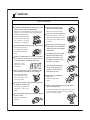
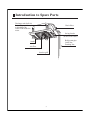
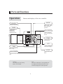
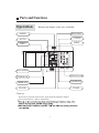
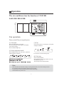
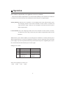
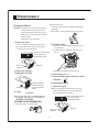
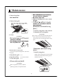
CASSETTE TYPE AIR CONDITIONER
Operation & Installation
Manual
AB482XCAAA
AB242XCAAA
No.0010576262
Please read this operation manual before using the air conditioner.
Please keep this manual carefully and safely.
Contents
Cautions ............................................................................................. 1-4
Introduction to Spare Parts................................................................... 5
Parts And Functions.......................................................................... 6-7
Operation ......................................................................................... 8-13
Maintenance....................................................................................14-16
Trouble Shooting.......................................................................... 17-18
When Trouble Happens...................................................................... 19
Customer Need-to-know...................................................................... 20
Installation Procedure .................................................................... 21-33
Cautions
Disposal of the old air conditioner
Before disposing an old air conditioner
that goes out of use, please make sure it's
inoperative and safe. Unplug the air
conditioner in order to avoid the risk of
child entrapment.
It must be noticed that air conditioner
system contains refrigerants, which require
specialized waste disposal. The valuable
materials contained in a air conditioner can
be recycled. Contact your local waste
disposal center for proper disposal of an
old air conditioner and contact your local
authority or your dealer if you have any
question. Please ensure that the pipework
of your air conditioner does not get
damaged prior to being picked up by the
relevant waste disposal center, and
contribute to environmental awareness by
insisting on an appropriate, anti-pollution
method of disposal.
Disposal of the packaging of your new
air conditioner
All the packaging materials employed in
the package of your new air conditioner
may be disposed without any danger to the
environment.
The cardboard box may be broken or cut
into smaller pieces and given to a waste
paper disposal service. The wrapping bag
made of polyethylene and the polyethylene
foam pads contain no fluorochloric
hydrocarbon.
All these valuable materials may be taken to a
waste collecting center and used again after
adequate recycling.
Consult your local authorities for the name and
address of the waste materials collecting
centers and waste paper disposal services
nearest to your house.
Safety Instructions and Warnings
Before starting the air conditioner, read the
information given in the User's Guide
carefully. The User's Guide contains very
important observations relating to the
assembly, operation and maintenance of the
air conditioner.
The manufacturer does not accept
responsibility for any damages that may
arise due to non-observation of the following
instruction.
Damaged air conditioners are not to be
put into operation. In case of doubt, consult
your supplier.
Use of the air conditioner is to be carried
out in strict compliance with the relative
instructions set forth in the User's Guide.
Installation shall be done by professional
people, don't install unit by yourself.
For the purpose of safety, the air
conditioner must be properly grounded in
accordance with specifications.
Always remember to unplug the air
conditioner before opening inlet grill. Never
unplug your air conditioner by pulling on the
power cord. Always grip plug firmly and
pull straight out from the outlet.
1
Cautions
All electrical repairs must be carried out
by qualified electricians. Inadequate repairs
may result in a major source of danger for
the user of the air conditoiner.
Do not damage any parts of the air
conditioner that carry refrigerant by
piercing or perforating the air conditioner's
tubes with sharp or pointed items, crushing
or twisting any tubes, or scraping the
coatings off the surfaces. If the refrigerant
spurts out and gets into eyes, it may result
in serious eye injuries.
Do not obstruct or cover the ventilation
grille of the air conditioner. Do not put
fingers or any other things into the
inlet/outlet and swing louver.
Do not allow children to play with the air
conditioner. In no case should children be
allowed to sit on the outdoor unit.
2
Cautions
Safety cautions
Carefully read the following information in order to operate the airconditioner correctly.
Below are listed three kinds of Safety Cautions and Suggestions.
WARNING! Incorrect operations may result in severe consequences of death or serious injuries.
CAUTION! Incorrect operations may result in injuries or machine damages; in some cases may
cause serious consequences.
INSTRUCTIONS: These information can ensure the correct operation of the machine.
Be sure to conform with the following important Safety Cautions.
The Safety Cautions should be at hand so that they can be checked at any time when needed.
If the conditioner is transferred to the new user, this manual should be as well transferred to the new user.
WARNING!
Don't blow the human body with the cooling
air too long, and don't let the room temperature decrease too low
either.
Please let the dealer be responsible for installing
the conditioner.
Incorrect installation may cause water leak, electrical shock and fire hazard.
Otherwise the one
will feel unpleasant
or harm ones' health.
Don't put fingers or any other things into the
inlet/outlet and swing louver while the conditioner is in operation.
Because the highspeed
fan is very dangerous
and may cause injuries.
If any abnormal phenomena is found (e. g.
smell of firing), please cut off the power
supply immediately, and contact the dealer
to find out the handling method.
In such case, to continue
using the conditioner will
switch
damage the conditioner,
off
and may cause electrical
shock or fire hazard.
Call the dealer to take measures to prevent the
refrigerant from leaking.
If conditioner is installed in a small room be sure
to take every measure in order to prevent suffocation accident even in case of refrigerant leakage.
When need maintenance and repairment,
call dealer to handle it.
Incorrect maintenance and repairment
may cause water
leak, electrical shock
and fire hazard.
When conditioner is deinstalled or reinstalled
dealer should be responsible for them.
Incorrect installation may cause water leaking,
electrical shock and fire hazard.
3
Cautions
CAUTIONS!
Don't operate the air-conditioner with damp hands.
Otherwise will be shocked.
Conditioner should not be used for any other
purpose other than airconditioning.
Don't use air-conditioner for any other special
purposes, e.g. the preservation and protection
of food, animals, plants,
pecision apparatus as well
as work of art, otherwise
the qualities of these
stuffs may be damaged.
Only use correctly-typed fuse.
May not use wire or any other
materials replacing fuse, otherwise may cause faults or fire
accidents.
Don't place any burning unit
in the air flow of air-conditioner,
which may cause incomplete
combustion.
Don't dismantle the outlet of the outdoor unit.
The exposure of fan is
very dangerous which
may harm human beings.
No inflammable spray fluid
should be permitted to be
placed or used near to airconditioner otherwise may
cause fire accidents.
When air-conditioner is co-used with other
heat-radiator the frequent replacement of
room atmosphere should be required.
Inefficient ventilation may cause
suffocation.
Air-conditioner should be
cleaned only after power
supply is cut off to keep
from shock or hurt.
After a long time use of air-conditioner the
base should be checked for any damages.
If the damaged base is
not repaired, the unit
may fall down and
cause accidents.
Don't clean air-conditioner
with water.
Otherwise may cause
shock.
No goods or nobody is permitted to placed on
or stand on outdoor unit.
The falling of goods and
people may cause accidents.
When use the fumigating insecticide don't
open air-conditioner.
Otherwise the poisonous chemicals may settle
in air-conditioner which harm the health of
chemical-allergic people.
Pets and plants should not be blowed directly
in the air flow.
Otherwise will suffer
damage.
4
Introduction to Spare Parts
Discharge unit (built in)
In cooling operation,
to discharge the
water from inside the
room.
Drain Hose
Swing fender
(located in the outlet)
Refrigerant pipe
Cable line
Earthing line
Outlet
Air filter
(located in the suction grill)
Suction grill
5
Parts and Functions
Operation
Buttons and display of the wire controller.
MODE
CLOCK
Used to select AUTO
RUN, COOL, DRY,
HEAT and FAN
operation.
Used to set correct time.
TIMER
Used to select
TIMER ON,
TIMER OFF,
TIMER ON/OFF.
FAN SPEED
Used to select fan
speed: LO, MID, HI,
AUTO
TEMP
Used to select your
desired temp.
SET
Used to confirm Timer
and Clock settings.
TIME
Used to set clock and
timer setting.
SLEEP
Power ON/OFF
Used to select sleep
mode.
Used for unit start and
stop.
Cautions:
On cooling only unit, heating
mode is not available.
Note:
The above information is the explanation of
the displayed information therefore varies
with those displayed in actual operation.
6
Parts and Functions
Operation
Buttons and display of the wire controller.
SLEEP
Remote control
COOL
AUTO
HEAT
DRY
FAN SPEED
OPERATING LAMP
TIMER ON
FAN OPERATION
TIMER OFF
TEMP.
CLOCK
Clock set
When unit is started for the first time, clock should be adjusted as follows:
Press CLOCK button, "AM"or "PM" flashes.
7
Operation
The air conditioner has the function of POWER
FAILURE RESUME.
Fan operation
Enjoy yourself by just a gentle press.
(1) Unit start
(3) Fan
Press ON/OFF button, unit starts.
Previous operation status appears on display.
(Not Timer setting)
Power indicator lights up.
Press FAN button. For each press, fan speed
changes as follows:
LOW
(2) Select operation mode
Press MODE button. For each press, operation
mode changes as follows:
AUTO
COOL
DRY
HEAT
MID
HIGH
Unit will run at selected fan speed.
(4) Unit stop
FAN
Press ON/OFF button.
Only time and room temp remains on LCD.
All indicators go out.
Vertical flap closed automatically.
Hints
Wire controller can memorize settings in each operation mode. To run it next time just select
the operation mode and it will start with the previous setting.
No reselecting is needed.(TIMER ON/OFF needs reselecting)
In FAN mode, temp. can't be set.
8
Operation
AUTO RUN, COOL,HEAT and DRY operation
Recommendations
Use COOL in summer.
Use HEAT in winter.
Use DRY in spring,autumn and in damp climate.
(1) Unit start
(4) Fan speed selection
Press ON/OFF button, unit starts.
Previous operation status appears on display
(Not Timer setting). Power indicator lights up.
Press FAN button. For each press, fan speed changes
as follows:
AUTO
(2) Select operation mode
LOW
Press MODE button. For each press, operation mode
changes as follows:
AUTO
COOL
DRY
HEAT
MID
HIGH
AUTO
FAN
Unit will run in operation mode displayed on LCD.
Stop display at your desired mode.
(3) Select temp. setting
(5) Unit stop
Press TEMP button
Press ON/OFF button.
Only time and room temp remains on LCD.
All indicators go out.
Vertical flap closes automatically.
Hints
Wire controller can memorize each operation
status. When starting it next time, just press
ON/OFF button and unit will run in previous
status.
Unit will start running to reach the temp. setting
on LCD.
9
Operation
TIMER operation
Set Clock correctly before starting Timer operation.
You can let unit start or stop automatically at following time: Before you wake up in the
morning, or get back from outside or after you fall asleep at night.
TIMER ON/OFF
(3)Timer setting
(1)After unit start, select your desired
operation mode.
Operation mode will be displayed on LCD.
Power indicator lights up.
Every time the button is pressed, time increases 10min.
If button is kept depressed, time will change quickly.
Every time the button is pressed, time decreases 10min.
If button is kept depressed, time will change quickly.
Time will be shown on LCD. It can be adjusted within
24hours.
(2)TIMER mode selection
Press TIMER button to change TIMER mode.
Every time the button is pressed, display changes
as follows:
ON
ON
OFF
(4)Confirming your setting
After setting correct time, press SET button to confirm
"ON" or "OFF" stops flashing.
Time displayed: Unit starts or stops at x hour x min (ON
or OFF).
Timer mode indicator lights up.
blank
OFF
Select your desired TIMER mode (ON or OFF)
To cancel TIMER mode
Just press TIMER button several times until TIMER mode disappears.
Hints
Wire controller possesses memory function, when use TIMER mode next time, just
press SET button after mode selecting if timer setting is the same as previous one.
10
Operation
TIMER ON-OFF
(1)After unit start, select your desired
operation mode
(4) Time confirming for TIMER ON
After time setting, press TIMER button to confirm.
"ON" stops blinking, While "OFF" starts blinking.
Operation mode will be displayed on LCD.
Power indicator lights up.
Time displayed: Unit starts at Xhour X min.
(2) Press TIMER button to change TIMER
mode
Every time the button is pressed, display changes as follows:
ON
ON
OFF
(5)Time setting for TIMER OFF
Follow the same procedures in "Time setting for
TIMER ON".
blank
OFF
(6)Time confirming for TIMER OFF
Select
ON
OFF .
After time setting, press SET button to confirm
"OFF" stops flashing.
(3)Time setting for TIMER ON
Time displayed: Unit stops at X hour X min.
Press TIME button.
Every time the button is pressed, time increases 10min.
If button is kept depressed, time will change quickly.
Every time the button is pressed, time decreases 10min.
If button is kept depressed, time will change quickly.
Time will be shown on LCD.
It can be adjusted within 24hours.
AM refers to morning and PM to afternoon.
To cancel TIMER mode
Just press TIMER button several times until TIMER mode disappears.
According to the Time setting sequence of TIMER ON or TIMER OFF, either Start-Stop or Stop-Start can
be achieved.
11
Operation
Comfortable Sleep
At night, before going to bed you
can press down the SLEEP button
on the controller and the airconditioner will run by the
comfortable sleeping mode to
make you sleep more comfortable.
In cooling, dehumidifying mode
In heating mode
Note:
In AUTO mode, unit will run in SLEEP function according to the operation mode.
After setting SLEEP function, it is forbidden to calibrate clock.
If the set sleep-time does not reach 8 hours, the unit will stop operation automatically after
set time is complete.
Set "TIMER-OFF" function first, then set SLEEP, and the sleep-set is performance; set
TIMER-ON function first, the sleep function can only be set before TIMER-ON; if set theSLEEP
function first, the TIMER function can not be set.
SETTING T
SLEEP RUN BEGINS
SHUT DOWN
SLEEP RUN STOPS
about 6 hrs
1 hr
1 hr
1 hr
about 3 hrs
1 hr
3 hrs
SHUT DOWN
SETTING T
SLEEP RUN BEGINS
SLEEP RUN STOPS
Cooling mode
Heat mode
12
Operation
Power Failure Compensation (to be applied for a necessary situation)
After the power failure compensation is set, if power failure suddenly occurs while the air conditioner
is working, it will resume the previous working state when the power is supplied again.
Setting Method: When the wire controller is on (excluding timer mode and fan mode), press
the "Sleeping" button on the remote controller 10 times within 5 seconds, and
after the buzzer rings 4 times, the air conditioner will enter the state of power
failure compensation.
Cancel Method: Press the "Sleeping" button on the wire controller 10 times within 5 seconds,
and after the buzzer rings 2 timer, the power failure compensation mode will be
cancelled.
Notes: When a power failure suddenly occurs during the air conditioner is working after the power
failure compensation is set, if the air conditioner will not be used for a long time, please cut off the
power supply to prevent its operation from being resumed after the power is supplied again, or press
the "Switch On/Off" button after the power comes again.
Change-over switch
Mark
1
2
3
4
ON
Fixed Frequency
Have rise and drop
Swing
The collection
temperature of
indoor unit
OFF
Inverter
No rise and drop
Not Swing
The collection
temperature of wire
controller.
In this series changeover switch is set:
1. OFF 2.OFF
3.ON
4.OFF
13
Maintenance
[Clean air filter]
NOTE When having to clean, don't dismantle
air-filter,otherwise may cause faults.
In the environment where there is too
much dust, air filter should be cleaned
for more times.
(about half a year one time)
(B) Wash with water.
With too much dust, use soft brush and neutral
detergent.
Swing off the water, and then place in cool place.
1. Open inlet grill
5. Install air filter
Press the elliptical "PUSH" knob, the inlet
grill will automatically drop. (the inlet grill
is catched with two pothooks)
(1) Put filter into protruding parts at the top of
the inlet grill.
(2) Connect the two pothooks with inlet grill
See 2
Press the elliptical knob
the inlet grill will
automatically drop
PUSH
Pothook
Open two
pothooks
2. Open two othooks
3. Dismantle air filter
Air filter
Connet the two pothooks with inlet grill
6. Close inlet grill See 1.
7. Press the filter signal return key on the
''
controller. ''
[Clean inlet grill]
Drag the knob of
the grill back lift
the filter and take
down.
1. Open inlet grill
Press the elliptical "PUSH" knob, the inlet
grill will automatically drop. (the inlet grill
is catched with two pothooks)
4. Clean
CAUTION!
PUSH
Press the elliptical knob
the inlet grill will
automatically drop
(A) Remove dust with vacuum filter.
Open two
pothooks
14
Pothook
Maintenance
2. Take off air-filter
3. Take of inlet grill
[Dismantle and install swing
plate ]
1. Fix the swing plate at the bottom.
2. Dismantle the swing plate.
CAUTION!
Use water to clean the plate and don't heavily
scrub, otherwise the fine hair may fall off.
Unscrew the screw at both ends of the swing
plate.
4. Clean
CAUTION!
NOTE
[Dismantle and install swing
plate ]
When the filter too much dust
To spray the special detergent for vent fan or
utensils.
3. Install swing plate
Lightly rotate swing plate to insert the ridge
5. Install inlet grill see 3
6. Install air filter see "Clean air filter"
7. Close inlet grill see 1
at both ends of the outlet into the groove
and then screw up.
[Clean outlet and shell]
CAUTION!
Don't use gasoline, benzene, dilutant,
polishing powder, or liquid inseticide.
15
Maintenance
Seasonal Reserve
Post-season Care
Operate the unit with FAN mode on a fair day for about half
a day to dry the inside of the unit well.
Stop operation and turn off the power supply switch .Electric
power is consumed even the air conditioner is in stop.
Clean the air filter, indoor unit and outdoor unit,and cover
the unit with dustcoat.
Pre-season Care
See that there is no obstacles blocking the air
inlet and air outlet of both indoor and outdoor
unit to avoid reduce the working efficiency.
Be sure to install the air filter, ensure that the air filter is not dirty. Otherwise may result in
machine damages or cause malfunciton due th dust inside the unit
To prevent compressor when start in HEAT mode,
please cut in the power supply switch 12 hours
before starting run,furthermore, always keep the
power supply switch on during the using senson.
NOTE
1. The inner part of indoor unit must be cleaned. Consult dealer, because clean must be done by
technician.
2. In cooling operation, discharging system discharge water in room.
16
Trouble Shooting
The followings are not malfuncition
When the air conditoner is started, when the
compressor starts or stops during operation
or when the air conditioner is stopped,it sometimes sounds ì Bi- Bi-î or ì Godo-Godoî . It is
the flowing sound of the refrigerant , not a
malfunction.
Water flowing sound is heard
Hua
Hua
Cracking sound is heard
This is caused by heat expansion or contraction of plastics
It smells.
Air blown out from the indoor unit sometimes
smells. The smell results from smells of
furniture, paint , tobacco absorbed by indoor
unit.
During operation, white fog comes out of
indoor unit.
When in COOL or DRY mode, a thin water
fog can be seen blown out of unit ,this is the
condensed fog because the suddenly cooled
indoor air is blown out.
Automatically switch into FAN mode during
cooling.
To prevent frost from being accumulated on the
indoor unit heat exchanger, it sometimes automatically switched into the FAN mode,but it will
soon back to the cooling mode.
The air conditioner cannot be restarted soon
after it stops.
Air conditioner does not start?
This is because of the self-protection function
of the system, therefore,it cannot be restarted
for about three minutes after it stops.
Please wait for
three minutes
17
Trouble Shooting
Air does not blow or the fan speed cannot be
changed during drying.
In DRY mode, when room temperature
becomes 2 C higher than temperature setting,
unit rill run intermittently at LO speed regardless
of FAN setting
This happens when the frost accumulated on
the outdoor unit is removed (during defrosting
operation).
Water or vapor generated from the outdoor
unit during heating.
Defrosting operation
During heating,indoor fan is still running even
unit is stopped.
To get ride of the excess heat, indoor fan will
continue running for a while after unit automatically stops.
Please check the following things about your air conditioner before making a
service call.
Unit fails to start.
Is the power supply switch on ?
Is city supply power normal ?
Is the earth leakage breaker
in action ?
Be sure to turn off the power
supply switch immediately and
contact the sales dealer.
**?
ON
OFF
Power supply switch is not in
ON position.
18
When Trouble Happens
Insufficient cooling or heating
The operation controller
adjusted as required
Any obstacle exists at the air
inlet or outlet?
Air filter too dirty ?
Horizontal swing louver
upward ? (in HEAT mode)
Door or window left opened ?
Insufficient cooling
Any other heat sources in the
room?
Sunlight direct into the
room ?
Too crowed in the room ?
Cooled air blown out ( when heating)
When the air conditioner does not operate properly after
you have checked the above-mentioned items or when
following phenomenon is observed,stop the operation of
the air conditioner and contact your sales dealer.
1)The fuse or breaker often shuts down.
2)Water drops off during cooling or drying operation.
3)There is an irregularity in operation or abnormal sound that
is audible.
19
Customer Need-to-know
Customer Need-to-know
Please install the air conditioner according to the requirements specified in this manual to ensure
the air conditioner work well.
Be careful not to scratch the surface of the case during moving the air conditioner.
Please keep the installation manual for future reference when maintenance and changing installation place.
After installation ,please use the air conditioner according to the specification in the operation
manual.
Using Directions
Avoid direct sunlight and airflow
Adjust suitable airflow direction
Keep the proper indoor temperature.
Too cool or hot is not good for your health.
Furthermore,it will result in excessive
consumption of electric power.
Effectively use timer.
Using TIMER mode, you can make the room
temperature reach a suitable temperature when
you wake up or back home.
Optimal
temperature
ATTENTION: after finishing installation,confirm no refrigerant leakage.
20
Installation Procedure
Installation
Please ask the dealer or specialist to install, never try by the users themselves. After the installation please
be sure of the following conditions.
WARNING !
Please call dealer to install the air-conditioner.
Incorrect installation may cause water leaking, shock and fire hazard.
CAUTION !
Air-conditioner can't be installed in the environment with inflammable gases because the
inflammable gases near to air-conditioner may
cause fire hazard.
Connect earthing wire.
Earthing wire should not be connected to the gas pipe, water pipe,
lightning rod or phone line, incorrect earthing may cause shock.
Installed electrical-leaking circuit breaker.
It easily cause electrical shock without circuit
breaker.
Earthing
Use discharge pipe correctly to ensure efficient
discharge.
Incorrect pipe use may cause water leaking.
[Location]
Air-conditioner should be located in well-vented
and easily-accessible place.
Air-conditioner should not be located in the
following places:
(a) Places with machine oils or other oil vapours.
(b) Seaside with high salt content in the air.
(c) Near to hot spring with high content of sulfide
gases.
(d) Area with frequent fluctuation of voltage e.g.
factory, etc.
(e) In vehicles or ships.
(f) Kitchen with heavy oil vapour or humidity.
(g) Near to the machine emitting electric-magnetic
waves.
(h) Places with acid, alkali vapuor.
TV, radio, acoustic appliances etc are at least 1 m
far away to the indoor unit, outdoor unit, power
supply wire, connecting wire, pipes, otherwise
images may be disturbed or noises be created.
As required, take measures against heavy snow.
[Wiring]
Air-conditioner should be equipped with special
power supply wire.
[Operating noise]
Chose the following locations:
(a) Capable of supporting air-conditioner weight,
don't increase operating noise and vibration.
(b) Hot vapour from outdoor unit outlet and operating noise don't disturb neighbour.
No obstacles around the outdoor unit outlet.
21
Installation Procedure
CAUTIONS: To ensure proper installation, read "Cautions" carefully before working. After
installation, start the unit correctly and show customers how to operate and
maintain the unit.
Meanings of Warning and Cautions:
Warning! Serious injury or even death might happen, if it is not observed.
Caution! Injury to people of damages to machine might happen, if it is not observed.
WARNING!
Installation shall be done by professional people, don't install unit by yourself. Incorrect installation will
cause water leakage, electric shock or fire.
Install unit as per the Manual. Incorrect installation will cause water leakage, electric shock or fire
accident.
Be sure to use specified accessaries and parts. Otherwise, water leakage, electric shock, fire accident or
unit falling down may happen.
Unit should be placed on a place strong enough to hold the unit. Or, unit will fall down causing injuries.
When install the unit, take in consideration of storms, typhoom, earthquake. Incorrect installation may
cause unit to fall down.
All electric work shall be done by experienced people as per eocal code, regulations and this Manual.
Use exclusive wire for the unit. Incorrect installation or undersized electric wire may cause electric
shock or fire accident.
All the wires and circuit shall be safe. Use exclusive wire firmly fixed. Be sure that external force
will not affect terminal bolck and electric wire. Poor contact and installation may cause fire accident.
Arrange wire correctly when connectin indoor and outdoor power supply. Fix terminal cover firmly to
avoid overheat, electric shock or even fire accident.
In case retrigerant leakage occurred during unit installation, keep a good ventilation in the room.
Poisonous gas will occur when meet with fire.
Check the unit upon installation. Be sure there is no leakage. Refrigerant will induce poisonous gas
when meet heat source as heater, oven, etc.
Cut power supply before touching terminal bolck.
CAUTION!
Unit shall be grounded. But grounding shall not be connected to gas pipe
water pipe, telephone line. Poor grounding will cause electric shock.
Be sure to install a leakage breaker to avoid electric shock.
Earthing
Arrange water drainage according to this Manual. Cover pipe with insulation materials in case
dew may occur. Unproper installation of water drainage will cause water leakage and wer your furniture.
To maintain good picture or reduce noise, keep at least 1 m from T.V. radio, when install indoor and ou
tdoor unit, connecting wire and power line. (If the radio wave is relatively strong, 1 m is not enough
to reduce noise).
Don't install unit in following places:
(a) Oil mist or oil gas exists, such as kitchen, or, plastic parts may got aged, or water leakage.
(b) Where there is corrosive gas. Copper tube and welded part may be damaged due to corrosion,
causing leakage.
(c) Where there is strong radiation. This will affect unit's control system, causing malfunction of the unit
(d) Where flamable gas, dirt, and volatile matter (thinner, gasoline) exist, These matter
might cause fire accident.
Refer to paper pattern when installing unit.
Cautions for the installation personnel
Don't fail to show customers how to operate unit.
22
Installation Procedure
Installation tools
The installation tools listed in the
following sheet can be used as required.
1. Screw driver
2. Hacksaw
3. Drill with a diameter of 60mm
4. Inner hexagon spanner,shifting
spanner
5. Spanner (14, 17, 19,24,27mm)
6. Pipe cutter
7. Pipe expander
8. Knife
9. Pincers
10. Leakage detector or soapy water
11. Band tape
12. Scraper
13. Refrigerant oil
Following in the list are the accessories
supplied with the unit,which can be used
as required
No.
1
Standard accessories
The following parts mentioned in this
manual are the installation accessories
we prepared.
Symbol
Parts Name
A
Adhesive tape
B
Pipe clamp
C
Connecting hose
D
Drainage hose
E
Gypsum powder
F
Non-hydroscopic
heat insulating material
23
Accessory parts
Wire controller
Qty.
1
2
Wire clamp
3
Heat
insulation
sheathing
1+1
4
Accesories
1
5
Screw cap
1+1
4
Installation Procedure
1 BEFORE INSTALLATION
1.
<Don't discard any accessories until comp>
Determine the way to carry unit to installation place.
Don't remove packing until unit reaches installation place.
If unpacking is unkavoidable, protect unit properly.
2 SELECTION OF INSTALLATION PLACE
2.
(1) Installation place shall meet the following and agreed by customers:
Place where proper air flow can be ensured.
No block to air flow.
Water drainage is smpoth.
Place strong enough to support unit weight.
Place where inclination is not evident on ceiling.
Enough space for mainenance.
Indoor and outdoor unit piping length is within limit. (Refer to Installation Manual for outdoor unit.)
Indoor and outdoor unit, power cable, inter unit cable are at least 1 m away fromT.V. radop. This is helpful
to avoid picture disturbance and noise. (Even if 1 m iskept, noise can still appear if radio wave is strong)
(2) Ceiling height
Indoor unit can be installed on ceiling of 2.5-3m in height. (Refer to Foeld setting and Installation Manual of
ornament panel.)
Air outlet
1500 Over
2500 Over
260
(3) Install suspending bolt. Check if the installation place is strong enough to hold weight. Take necessary
measures in case it is not safe. (Distance between holes are marked on paper pattern. Refer to paper pattern
for place need be reinforced)
Air inlet
Air outlet
1500 Over
24
Installation Procedure
3 PREPARATION FOR THE INSTALLATION
3.
Refrigerant pipe
Suspending bracket
(160)
780
(Distance between suspending bolts)
840(Indoor unit)
890(Ceiling opening)
950(Ornament panel)
(1) Position of ceiling opening between unit and suspending bolt.
Suspending bolts
Ceiling
A (Distance between suspending bolts)
A
840(Indoor unit)
890(Ceiling opening)
950(Ornament panel)
A
(2) Cut an opening in ceiling for installation if necessary. (when ceiling already exists.)
Refer to paper pattern for dimension of ceiling hole.
Connect all pipings (refrigerant, water drainage), wirings (inter unit cable) to indoor unit, before installation.
Cut a hole in ceiling, may be a frame should be used to ensure a smooth surface and to prevent vibration.
Contact your real estate dealer
50~100
(3) Install a suspending bolt.
(Use a M10 bolt)
To support the unit weight, anchor bolt shall be used in the case of already exists ceiling. For new
ceiling, use built-in type bolt or parts prepared in the field.
Before going on installing adjust space between ceiling.
<Installation example>
Roof
Anchor bolt
Long nut
Suspending bolt
Ceiling
Note: All the above mentioned parts shall be prepared in field.
25
Installation Procedure
4 INSTALLATION OF INDOOR UNIT
4.
In the case of new ceiling
(1) Install unit temporally
Put suspending bracket on the suspending bolt. Be sure to use nut and washer at both ends of the bracket.
(2) As for the dimensions of ceiling hole, see paper pattern. Ask your real estate dealer for details.
Center of the hole is marked on the paper pattern.
Center of the unit is marked on the card in the unit and on the paper pattern.
Mount paper pattern 5 onto unit using 3 screws 6 . Fix the corner of the drain pan at piping outlet.
< After installation on the ceiling >
(3) Adjust unit to its right position. (Refer to preparation for the installation-(1))
(4) Check unit's horizontal level.
Watert pump and flating switch is installed inside indoor unit, check four corners of the unit for its level
using horizontal compartor or PVC tube with water. (If unit is tilting against the direction of water drainage,
problem may occur on floating switch, causing water leakage.)
(5) Remove the washer mounlting 2 , and tighten the nut above.
(6) Remove the paper pattern.
Nut (Prepare in feild)
Washer (Prepared in feild)
In the case of ceiling already exists
(1) Install unit temporally
Put suspending bracket on the suspending bolt.
Be sure to use nut and washer at both ends
of the bracket. Fix the bracket firmly.
(2) Adjust the height and position of the unit.
(Refer to preparation for the installation (1) ).
(3) Proceed with 3 and 4 of "In the case of new ceiling".
Suspending bolts
Fasten (double nuts)
Insert
Level
Washer fixing pad
(prepared in feild)
[ secure the washer firmly]
Polythene pipe
Screws at the piping outlet is fixed at the corner
of drain pan.
Center of ceiling hole Paper pattern
Screw (accessory)
[Fix the paper pattern]
26
Paper pattern 5
Screw (accessory)
Installation Procedure
5 REFRIGERANT PIPING (As for outdoor piping, please refer to installation Manual of outdoor unit.)
5.
Outdoor is precharged with refrigerant.
Be sure to see the Fig.1, when connecting and removing piping from unit.
For the size of the flare nut, please refer to Table 1.
Apply refrigerant oil at both inside and outsid of l flare nut. Tighten it band tight 3-4 turns then tighten it.
Use torque specified in Table 1. (Too much force may damage flare nut, causing gas leakage).
Check piping joints for gas leakage. Insulate piping as shown in Fig. below.
Cover joint of gas piping and insulator 7 with seal.
Table 1
Medium size seal pad (accessory)
Pipe
size
11
(Cover the piping joint
with seal pad.)
3270~3990N.cm
9.52 (333~407kgf.cm) 12.0~12.4
Clamp 3
Insulator(accessory) 8
(For liquid pipe)
spanner
Gas pipe
Liquid pipe
Flare nut
Flare shape
A(mm)
6.35 1420~1720N.cm 8.3~8.7
(144~176kgf.cm)
Torque spanner
Piping joing
Tighten
torque
Insulator(accessory) 7
(For gas pipe)
4950~6030N.cm
15.4~15.8
(504~616kgf.cm)
6180~7540N.cm
18.6~19.0
15.88
(630~770kgf.cm)
9720~11860N.cm
22.9~23.3
19.05
(990~1210kgf.cm)
12.7
90 0.5
45
2
A
Apple refrigerant oil
R0.4 ~ 0.8
6 INSTALLATION OF WATER DRAINAGE PIPE
6.
(1) Install water drainage pipe
Pipe dia, shall be equal or larger than that of unit piping.(pipe of polyethylent; size: 25mm; O.D:32mm)
Drain pipe should be short, with a downward slope at least 1/100 to prevent air bag from happening.
If downward slope can't be made, take other measures to lift it up.
Keep a distance of 1-1.5m between suspending brackets, to make water hose straight.
1-1.5m
Slope over 1/100
Use the self-provided stiff pipe and clamp 1 with unit. Insert water pipe into water plug until it reaches the
white tape. Tighten the clip until head of the screw is less than 4mm from hose.
Wind the drain hose to the clip using seal pad 9 .
Large size seal pad 10
Insulate drain hose in the room.
(accessory)
Clamp
Clamp
(accessory)
Tape (White)
Self-provided stiff pipe
<Cautions for the drain water lifting pipe>
Installation height shall be less than 280mm.
There should be a right angle with unit, 300mm from unit.
500 below
drain water lifting pipe
Self-provided stiff pipe
(accessory)
75 below
Suspending bracket
500 below
1~1.5m
220 280 below
300mm below
Drain hose
(accessory)
4mm below
Clamp
(accessory)
(Note)
Over 100
The slope of water drain hose (1) shall be within 75mm, don't apply too much force on it.
If several water hoses join together, do as per following proceedures.
Connect water hoses with a T joint.
Specifieations of the water hoses shall meet the requirements for the unit running.
27
Installation Procedure
(2) Check if water drainage is smooth after installation.
Charge, through air outlet or inspecting hole, 1200ccd water to see water drainage.
After wiring
Check water drainage in cooling operation.
When wiring is not complete
Remove cover of control box, short connect "CHECK" terminal of the indoor unit, which is on the uper
part of indoor unit PCB. Connect 1PH power to terminal 1 and 2 on terminal block.
Note, in this operation, fan will be running.
Upon confirmation of a smooth water drainage, be sure to cut off power supply
and remove short connection of "CHECK" terminal.
Method of water charging
Self-provided stiff pipe
Water drainage port for
maintenance
Maintenance
Inspecting hole
(Drain water from
this hole)
Charge water from
inspecting hole
100mm
Watering can of plastic
pipe should be about
100 mm long
Charge water from
air outlet
PCB on
indoor unit
Terminal block
Cover of controll box
28
Installation Procedure
7.
7 WIRING
All supplied parts. materials and wiring operation must in appliance with
local code and regulations.
Use copper wire only.
When make wiring, please refer to wiring diagram also.
All wiring work must be done by qualified electricians.
A circuit breaker must be installed, which can cut power supply to all system.
See Installation Manual of outdoor unit for specifications of wires, circuit breaker, switches and wiring etc.
Connecting of unit
Remove cover of switch box (1) , drag wires into rubber tube A, then, after proper wiring with other wires,
tighten clamp A. Connect wires of correct pole to the terminal block inside.
Wind seal 12 around wires. (Be sure to do that, or, dew may occur).
Upon connecting, replace control box cover (1) and (2).
Terminal block
Cover of control box(2)
*
Grounding lead
Rubber tube A
Cover of control box(1)
Don't fail to seal it, or water may come in.
Rubber tube Note: Have it sealed, leaving no space.
Seal pad (small size 12 )
(Wind around wire)
In Out
Attach seal pad Field wiring
<<WARNING>>
Connect wires of the
Obscrve the following when connecting power supply
same specifications
at two sides.
terminal block:
Don't connect wires of different specifications to the same
terminal block.
(Loose wire may cause overheating of circuit)
Connect wires of same specifications as shown in right Fig.
Don't connect wires of
the same specifications
at one side.
8 WIRING EXAMPLE
8.
As for outdoor unit circuit, please see Installation Manual of outdoor unit.
Note: All electric wires have their own poles, poles must match that on terminal block.
9
INSTALLATION OF WIRE CONTROLLER
1. Remove upper part of wire controller
Remove upper part of wire controller
PCB is mounted on lower part of wire controller, be careful not to damage it.
Upper part of wire
controller
Lower part of wire
controller
21
29
Don't connect wires
of the different
specifications.
Installation Procedure
2. Install wire controller
(1) For exposed installation,
use 2 wood screws (accessory).
(2) For recessed installation,
use 2 wood screws (accessory).
Note
Try as far as possible a flat surface for installation. Don't use excessive
force when tightening screws, or lower part might got deformed.
3. Indoor unit wiring
Hint
Connect terminals (A,B,C,D) on lower part of wire controller
When make wiring, please keep
to terminals (A,
a distance between wires and
B,C,D) on PCB of indoor unit.
power supply cord.
Wire size
wiring from here
AB
CD
Cord kind
Lower part of
wire controller
Shield wire (4 core) (refer to Hint 3,4)
0.33mm2
Size
Use shielede wires for telecommunication
between wire controller and indoor unit;
indoor unit and outdoor unit. Ground the
shield on one side.
Otherwise misoperation because of
noise may occur.
Signal wire is self-provided.
Shielded wire
Upper part of
wire controller
ground
30
Installation Procedure
Hint
Tread surface of the terminal well so that
shielding may not contact other part.
4. Replace the upper part of wire controller
Be careful not to press the wiring.
Hint
1. Switch box and cord for wiring are not supplied.
2. Don't touch PCB with hand.
10 INSTALLATION OF ORNAMENT PANEL
9.
Be sure to show customers Operation Manual and guide them how to operate unit
correctly. Before installation. read also the Installation Manual of indoor unit.
With this ornament , 2 or 3 air flow direction is not available.
Suitable height is 3 m.
Cautions for the installation
Accessory
Pad
Pad
1. Prepare ornament panel Handling of ornament panel
Ornament panel shall not be placed face down or against wall, neither
on an uneven object.
Don' t bend carelessly the swing flap, or, problem may occur.
(1) Remove air inlet grill from ornament panel *
1 Push in the bar on inlet grill and lift it up. (Refer to Fig. 1)
2 Lift it up for about 45 degree and remove it from ornament. Tear off adhesive
Bar
tape fixing air filter on the back of the air inlet grill. (Refer to Fig. 2)
Fig. 1
(2) Remove cover plate at corner
Tear off the adhesive tape, and slide it off. (Refer to Fig. 3)
Adbesive tape
45
Slide
Fig. 2
Fig. 3
31
Installation Procedure
2. Mounting on high ceiling
(1) Ornament panel can be mounted on ceiling as high as 3 m.
(2) Please install pad as accessary.
1 Cut open the pad along cutting ling. Use part a only and discard part b . (Refer to Fig. 4)
2 Install part a of the pad on the place shown in Fig. 5. Refer to Fig. 6.
Cutting line
Leave no space.
Place it on the frame.
a
50
100
b
Part a of the pad
Fig. 4
Fig. 6
Part a of the pad
Side of ornament panel
Swing flap motor
(3)Wiring on ornament panel
Connecting of wiring of the swing
flap motor on ornament panel. (2 places)
(Refer to Fit . 10)
Fig. 5
If connecting is not made, error code
(A7) appears on remote controller. So,
make proper connecting.
Fig. 10
Side of indoor unit
Wiring diagram
3. Install ornament panel on indoor unit.
For indoor unit installation, please
refer to Installation Manual.
(1) As shown in Fig . 7, match the position of swing
flap motor with that of the indoor unit piping hole ,
so that ormament panel can be placed on to indoor
unit.
(2) Installation of ornament panel
1 Place the holding ring on swing flao motor side
teporarily on hooks of the indoor unit. (2 pcs)
2 Put the other two holding rings on the hooks at both
side of the indoor unit. (Care should be taken not to
push wiring of swing flap motor into seals).
3 Screw in all 4 screws under holding ring for about
15mm. (Pancl will rise).
4 Adjust the ornament panel as per Fig. 7 to cover
opening on the ceiling.
5 Tighten screws to redrce the thickness of seals
between ornament and indoor unit to 5-8mm.
Hook
1
Holding ring
2
Piping hole position
2
Swing flap motor
3
4
Fig. 7
Indoor unit
Ceiling material
Seal
5 _ 8mm
Ornament panel
Caution
If screws are not tighten tight,
problems in Fig, 8 might occur.
Tighten screws properly.
Gas leakage.
If there are still space
after tightening of screws,
please readjust the height
of indoor unit.
(Refer to Fig. 9)
Gas leakage
from roof.
Contamination
Mist exists and drop down.
Fig. 8
Leave no space.
Fig. 9
32
If indoor unit is at horizontal level and water
drainage is smooth, then, indoor unit height
can be adjusted throrgh holes at corners of
ornament panel.