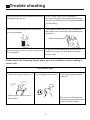
1
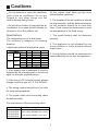
R410A MULTI SPLIT SERIES ROOM AIR CONDITIONER
LOW E.S.P. DUCT TYPE INDOOR UNITS
OPERATION & INSTALLATION MANUAL
AD092XLERA
AD122XLERA
AD142XLERA
AD182XLERA
No.0010577705
Please read this manual carefully before using this air conditioner.
Please keep this manual safely for future use.
Contents
Cautions ....................................................................................1-2
Safety precautions..................................................................... 3-5
Notes for safety.......................................................................... 6
Parts and Functions .................................................................. 7
Trouble shooting ....................................................................... 8-9
Customer Need-to-know ........................................................... 10
When trouble happens............................................................... 11
Operation and Maintenance ..................................................12-23
Failure code ......................................................................... 24-25
Cautions
Disposal of the old air conditioner
Safety Instructions and Warnings
Before disposing an old air conditioner
that goes out of use, please make sure it's
inoperative and safe. Unplug the air
conditioner in order to avoid the risk of
child entrapment.
Before starting the air conditioner, read the
information given in the User's Guide
carefully. The User's Guide contains very
important observations relating to the
assembly, operation and maintenance of
the air conditioner.
It must be noticed that air conditioner
system contains refrigerants, which require
specialized waste disposal. The valuable
materials contained in a air conditioner
can be recycled. Contact your local waste
disposal center for proper disposal of an
old air conditioner and contact your local
authority or your dealer if you have any
question. Please ensure that the pipework
of your air conditioner does not get
damaged prior to being picked up by the
relevant waste disposal center, and
contribute to environmental awareness by
insisting on an appropriate, anti-pollution
method of disposal.
The manufacturer does not accept
responsibility for any damage that may
arise due to non-observation of the following
instructions.
Damaged air conditioners are not to be
put into operation. In case of doubt, consult
your supplier.
Use of the air conditioner is to be carried
out in strict compliance with the relative
instructions set forth in the User's Guide.
Installation shall be done by professional
people, and don't install the unit by yourself.
Disposal of the packaging of your
new air conditioner
For the purpose of safety, the air
conditioner must be properly grounded in
accordance with specifications.
All the packaging materials employed in
the package of your new air conditioner
may be disposed without any danger to
the environment.
Always remember not to operate the air
conditioner before opening its inlet grill.
The cardboard box may be broken or cut
into smaller pieces and given to a waste
paper disposal service. The wrapping bag
made of polyethylene and the polyethylene
foam pads contain no fluorochloric
hydrocarbon.
All these valuable materials may be taken
to a waste collecting center and used
again after adequate recycling.
Consult your local authorities for the name
and address of the waste materials
collecting centers and waste paper
disposal services nearest to your house.
All electrical repairs must be carried out by
qualified electricians. Inadequate repairs
may result in a major source of danger for
the user of the air conditioner.
Do not damage any parts of the air
conditioner that carry refrigerant by piercing
or perforating the air conditioner's tubes with
sharp or pointed items, crushing or twisting
any tubes, or scraping the coatings off the
surfaces. If the refrigerant spurts out and
gets into eyes, it may result in serious eye
injuries.
1
Cautions
Do not obstruct or cover the ventilation
grille of the air conditioner. Do not put
fingers or any other things into the
inlet/outlet and swing louver.
Do not allow children to play with the air
conditioner. In no case should children be
allowed to sit on the outdoor unit.
Specifications
The refrigerating circuit is leak-proof.
The machine is adaptive in following
situation:
1.Applicable ambient temperature range:
DB
Indoor
WB
Cooling
outdoor DB
WB
DB
Indoor
Heating
WB
outdoor DB
WB
C
C
C
C
C
C
C
C
Rated
27
19
35
24
20
14.5
7
6
Maximum Minimum
32
18
23
14
43
10
26
6
27
15
--24
-15
18
--
All the cables shall have got the local
authentication certificate.
6. The breaker of the air conditioner should
be all-pole switch; and the distance between
its two contacts should be no less than
3mm. Such means for disconnection must
be incorporation in the fixed wiring.
7. The waste battery shall be disposed
properly.
8. The appliance is not intended for use
young children or infirm persons without
super vision.
9. Young children should be supervised to
ensure that they do not play the appliance.
2. If the supply cord is damaged, it must be
replaced by the manufacturer or its service
agent or a similar qualified person.
3. If the fuse on PC board is broken, please
change it with the type of T 3.15A /250VAC.
4. The wiring method should be in line with
the local wiring standard.
5. The power cable and connecting cable
are self-provided.
The requirement of the connecting cable:
Model
Connecting cable
AD092XLERA
AD122XLERA Power cable: H05RN-F 3G 2.5mm2
AD142XLERA Signal wires: H05RN-F 2X1.5mm2
AD182XLERA
2
Safety precautions
Carefully read the following information in order to operate the air conditioner
correctly.
Below are listed three kinds of Safety Cautions and Suggestions.
WARNING! Incorrect operations may result in severe consequences of death or serious injuries.
CAUTION! Incorrect operations may result in injuries or machine damages; in some cases may
cause serious consequences.
INSTRUCTIONS: These information can ensure the correct operation of the machine.
Be sure to conform with the following important Safety Cautions.
The Safety Cautions should be at hand so that they can be checked at any time when
needed.
If the conditioner is transferred to the new user, this manual should be as well transferred
to the new user.
WARNING!
Don't blow the human body with the cooling
air too long, and don't let the room
temperature decrease too low either.
Please let the dealer be responsible for
installing the conditioner.
Incorrect installation may cause water leak,
electrical shock and fire hazard.
Otherwise the one will feel unpleasant or harm
ones' health.
Don't put fingers or any other things into
the inlet/outlet and swing louver while the
conditioner is in operation.
If any abnormal phenomena is found (e. g.
smell of firing), please cut off the power
supply immediately, and contact the dealer
to find out the handling method.
In such case, to continue
using the conditioner will
damage the conditioner,
and may cause electrical
shock or fire hazard.
Because the highspeed fan is very dangerous
and may cause injuries.
Call the dealer to take measures to prevent
the refrigerant from leaking.
switch
off
If conditioner is installed in a small room, be
sure to take every measure in order to prevent
suffocation accident even in case of refrigerant
leakage.
When need maintenance and repairment,
call dealer to handle it.
When conditioner is deinstalled or reinstalled
dealer should be responsible for them.
Incorrect maintenance and repairment
may cause water
leak, electrical shock
and fire hazard.
Incorrect installation may cause water leaking,
electrical shock and fire hazard.
3
Safety precautions
CAUTIONS!
Conditioner should not be used for any
other purpose other than airconditioning.
Don't operate the air-conditioner with damp
hands.
Don't use air-conditioner for any other special
purposes, e.g. the preservation and protection
of food, animals, plants, pecision apparatus
as well as work of art, otherwise the qualities
of these stuffs may be damaged.
Otherwise will be shocked.
Only use correctly-typed fuse.
May not use wire or any other materials
replacing fuse, otherwise may cause faults or
fire accidents.
Don't dismantle the outlet of the outdoor
unit.
The exposure of fan is
very dangerous which
may harm human beings.
Don't place any burning unit in the air flow of
air-conditioner, which may cause incomplete
combustion.
When air-conditioner is co-used with
other h e a t - r a d i a t o r t h e f r e q u e n t
replacement of room atmosphere should
be required.
No inflammable spray fluid should be
permitted to be placed or used near to
airconditioner other wise may cause fire
accidents.
Inefficient ventilation may cause
suffocation.
Air-conditioner should be cleaned only after
power supply is cut off to keep from shock
or hurt.
After a long time use of air-conditioner
the base should be checked for any
damages.
If the damaged base is
not repaired, the unit
may fall down and
cause accidents.
Don't clean air-conditioner with water.
Otherwise may cause shock.
When use the fumigating insecticide don't
open air-conditioner.
No goods or nobody is permitted to placed
on or stand on outdoor unit.
Otherwise the poisonous chemicals may settle
in air-conditioner which harm the health of
chemical-allergic people.
The falling of goods and
people may cause accidents.
Pets and plants should not be blowed
directly in the air flow.
Otherwise will suffer damage.
4
Safety precautions
CAUTIONS ON INSTALLATION
Please ask the dealer or specialist to install, never try by the users themselves. After the installation
please be sure of the following conditions.
Please call dealer to install the air-conditioner.
Incorrect installation may cause water leaking, shock and fire hazard.
CAUTION !
Air-conditioner can't be installed in the
envi-ronment with inflammable gases
because the inflammable gases near to
air-conditioner may cause fire hazard.
Connect earthing wire.
Earthing wire should not be connected to the gas pipe, water
pipe, lightning rod or phone line,
in-correct earthing may cause
shock.
Installed electrical-leaking circuit breaker.
It easily cause electrical shock without circuit
breaker.
Use discharge pipe correctly to ensure
efficient discharge.
[Location]
Incorrect pipe use may cause water leaking.
Air-conditioner should be located in well-vented
and easily-accessible place.
Air-conditioner should not be located in the
following places:
(a) Places with machine oils or other oil
vapours.
(b) Seaside with high salt content in the air.
(c) Near to hot spring with high content of
sulfide gases.
(d) Area with frequent fluctuation of voltage
e.g. factory, etc.
(e) In vehicles or ships.
(f) Kitchen with heavy oil vapour or humidity.
(g) Near to the machine emitting electricmagnetic waves.
(h) Places with acid, alkali vapuor.
Earthing
As required, take measures against heavy
snow.
[Wiring]
Air-conditioner should be equipped with special
power supply wire.
[Operating noise]
Chose the following locations:
(a) Capable of supporting air-conditioner weight,
don't increase operating noise and vibration.
(b) Hot vapour from outdoor unit outlet and
operating noise don't disturb neighbour.
No obstacles around the outdoor unit outlet.
TV, radio, acoustic appliances etc are at least
1 m far away to the indoor unit, outdoor unit,
power supply wire, connecting wire, pipes,
otherwise images may be disturbed or noises
be created.
5
Notes for safety
!
The instructions with this warning mark must be carried out strictly,for they
are all concerned with safety of the product or human beings.
The instructions with this warning mark must be carried out strictly, for they are all
concerned with safety of the product or human beings.
Clean the dust filter periodically:
Blockage of the dust filter would reduce the cooling and heating effect, consume
more power, water would be leaked during cooling, and other failures would also
occur.
Use the fuse of required capacity:
Never use steel wire or copper wire to take place of the fuse.
Operate the unit with the remote controller.
The instructions with this prohibiting mark must be completely forbidden,
otherwise the product would be damaged or the human being would be injured.
Never connect the earth wire with the gas pipe, water pipe, lightening arrester, or
phone line.
Never install the air conditioner where the flammable gas is easily leaked.
Do not spray any paint or insecticide on the air conditioner.
Never pour water on the indoor unit.
Keep the inlet and outlet of the didoor unit unblocked.
When the louver is being swung, never touch the outlet or put anything into the air
grille.
6
Parts and Functions
INDOOR UNIT
Air inlet
Electrical box
Drain pan
Air outlet
7
Trouble shooting
The followings are not malfuncition
When the air conditoner is started, when the
compressor starts or stops during operation
or when the air conditioner is stopped,it sometimes sounds ì Bi- Bi-î or ìGodo-Godoî. It is
the flowing sound of the refrigerant , not a
malfunction.
Water flowing sound is heard
Hua
Hua
Cracking sound is heard
This is caused by heat expansion or contraction of plastics
It smells.
Air blown out from the indoor unit sometimes
smells. The smell results from smells of
furniture, paint , tobacco absorbed by indoor
unit.
During operation, white fog comes out of
indoor unit.
When in COOL or DRY mode, a thin water
fog can be seen blown out of unit ,this is the
condensed fog because the suddenly cooled
indoor air is blown out.
Automatically switch into FAN mode during
cooling.
To prevent frost from being accumulated on the
indoor unit heat exchanger, it sometimes auto
matically switched into the FAN mode,but it will
soon back to the cooling mode.
The air conditioner cannot be restarted soon
after it stops.
Air conditioner does not start?
This is because of the self-protection function
of the system, therefore,it cannot be restarted
for about three minutes after it stops.
Please wait for three minutes
8
Trouble shooting
Air does not blow or the fan speed cannot be
changed during drying.
Water or vapor generated from the outdoor
unit during heating.
In DRY mode, when room temperature
becomes 2 C higher than temperature setting,
unit rill run intermittently at LO speed regardless
of FAN setting
This happens when the frost accumulated on
the outdoor unit is removed (during defrosting
operation).
Defrosting operation
During heating,indoor fan is still running even
unit is stopped.
To get ride of the excess heat, indoor fan will
continue running for a while after unit automatically stops.
Please check the following things about your air conditioner before making a
service call.
Unit fails to start.
Is the power supply switch on ?
Is city supply power normal ? Is the earth leakage breaker
in action ?
**?
ON
OFF
Power supply switch is not in
ON position.
Be sure to turn off the power
supply switch immediately and
contact the sales dealer.
9
Customer Need-to-know
Customer Need-to-know
Please install the air conditioner according to the requirements specified in this manual to ensure
the air conditioner work well.
Be careful not to scratch the surface of the case during moving the air conditioner.
Please keep the installation manual for future reference when maintenance and changing
installation place.
After installation ,please use the air conditioner according to the specification in the operation
manual.
Using Directions
Adjust suitable airflow direction
Avoid direct sunlight and airflow
Keep the proper indoor temperature.
Too cool or hot is not good for your health.
Furthermore,it will result in excessive
consumption of electric power.
Effectively use timer.
Using TIMER mode, you can make the room
temperature reach a suitable temperature
when you wake up or go back home.
Best
temperature
ATTENTION!
After finishing installation, please confirm there is no refrigerant leakage.
10
When trouble happens
Insufficient cooling or heating
The operation controller adjusted as required
Air filter too dirty ?
Any obstacle exists at the air inlet or outlet?
Door or window left opened ?
Insufficient cooling
Any other heat sources in the
room?
Sunlight direct into the
room ?
Too crowed in the room ?
Cooled air blown out ( when heating)
When the air conditioner does not operate properly after
you have checked the above-mentioned items or when
following phenomenon is observed, stop the operation of
the air conditioner and contact your sales dealer.
1)The fuse or breaker often shuts down.
2)Water drops off during cooling or drying operation.
3)There is an irregularity in operation or abnormal sound
that is audible.
11
Instructions to installation
1. Safety precautions
Please read these "Safety Precautions" first then accurately execute the installation work.
Though the precautionary points indicated herein are divided under two headings,
WARNING
and
WARNING , those points which are related to the strong possibility of an installation done
CAUTION
in error resulting in death or serious injury are listed in the
section. However,
there is also a possibility of serious consequences in relationship to the points listed in the
CAUTION section as well.
In either case, important safety related information is indicated, so by all means, properly observe
all that is mentioned.
After completing the installation, along with confirming that no abnormalities were seen from the
operation tests, please explain operating methods as well as maintenance methods to the user
(customer) of this equipment, based on the owner's manual.
Moreover, ask the customer to keep this sheet together with the owner's manual.
WARNING
This system should be applied to places as office, restaurant, residence and the like. Application
to inferior environment such as engineering shop could cause equipment malfunction.
Please entrust installation to either the company which sold you the equipment or to a professional
contractor. Defects from improper installations can be the cause of water leakage, electric
shocks and fires.
Execute the installation accurately, based on following the installation manual. Again, improper
installations can result in water leakage, electric shocks and fires.
When a large air-conditioning system is installed to a small room, it is necessary to have a
prior planned countermeasure for the rare case of a refrigerant leakage, to prevent the exceeding
of threshold concentration. In regards to preparing this countermeasure, consult with the
company from which you perchased the equipment, and make the installation accordingly. In
the rare event that a refrigerant leakage and exceeding of threshold concentration does occur,
there is the danger of a resultant oxygen deficiency accident.
For installation, confirm that the installation site can sufficiently support heavy weight. When
strength is insufficient, injury can result from a falling of the unit.
Execute the prescribed installation construction to prepare for earthquakes and the strong
winds of typhoons and hurricanes, etc. Improper installations can result in accidents due to a
violent falling over of the unit.
For electrical work, please see that a licensed electrician executes the work while following
the safety standards related to electrical equipment, and local regulations as well as the
installation instructions, and that only exclusive use circuits are used.
Insufficient power source circuit capacity and defective installation execution can be the cause
of electric shocks and fires.
Accurately connect wiring using the proper cable, and insure that the external force of the
cable is not conducted to the terminal connection part, through properly securing it. Improper
connection or securing can result in heat generation or fire.
Take care that wiring does not rise upward, and accurately install the lid/service panel.
12
Instructions to installation
WARNING
Its improper installation can also result in heat generation or fire.
When setting up or moving the location of the air conditioner, do not mix air etc. or anything
other than the designated refrigerant within the refrigeration cycle.
Rupture and injury caused by abnormal high pressure can result from such mixing.
Always use accessory parts and authorized parts for installation construction. Using parts
not authorized by this company can result in water leakage, electric shock, fire and refrigerant
leakage.
CAUTION
Execute proper grounding. Do not connect the ground wire to a gas pipe, water pipe, lightning
rod or a telephone ground wire. Improper placement of ground wires can result in electric
shock.
The installation of an earth leakage breaker is necessary depending on the established
location of the unit. Not installing an earth leakage breaker may result in electric shock.
Do not install the unit where there is a concern about leakage of combustible gas.
The rare event of leaked gas collecting around the unit could result in an outbreak of fire.
For the drain pipe, follow the installation manual to insure that it allows proper drainage and
thermally insulate it to prevent condensation. Inadequate plumbing can result in water leakage
and water damage to interior items.
PRECAUTION
Execute proper grounding. Do not connect the earth wire to a gas pipe, water pipe, lightening
rod, or a telephone ground wire. Improper placement of earth wires can result in electric shock.
An electric leakage breaker must be installed, otherwise electric shock or other accidents would
occur.
After completion of the installation, the air conditioner shall be electrified to check for electric
leakage.
2. Preparation for installation
Installation tools
1
Screw Driver (flat head, wabbler, triangle) 8
Pipe Expander
2
Steel Saw
9
Knives
3
60mm Drill
10 Clippers
4
Inner Hexagon Spanner
11 Leakage Checker or Soap Liquid
5
Shifting Spanner
12 Measuring Tape
6
Spanner
13 Scraper or File
7
Pipe Cutter
14 Refrigeration Oil
13
Instructions to installation
3. Accessories for installation
Self-contained accessories
No.
A
B
C
D
E
Name of Non-adhesive Adhesive Connecting Heat insulation Gypsum
Parts
Tape
tape
Hose
material
powder
F
Drain hose
4. Choose the installation place
Install the indoor unit where the weight of the unit can be supported.
Install the indoor unit where the heat source and steam source are not close and the unit inlet
and outlet are not blocked.
Install the indoor unit where the drainage is easy and the outdoor unit can be easily connected.
Install the indoor unit where its cold air and hot air can be easily sent to all the corners of the
room.
Install the indoor unit where the power socket is near and there is sufficient space around the
indoor unit.
Install the indoor unit where there is no T.V set, radio set, and wireless appliance underneath,
and the sunlight lamp is over one meter away.
If the remote controller is installed on the wall, the indoor unit shall be ensured to receive the
signal while the sunlight lamp is on.
5. Installation procedure
1. Drill a hole in the wall and insert the connecting pipe and wire through a PVC wall-through tube
purchased locally. The wall hole shall be with a outward down slope of at least 1/100. (See
Figure 1)
2. Before drilling check that there is no pipe or reinforcing bar just behind the drilling position.
Drilling shall avoid at positions with electric wire or pipe.
3. Mount the unit on a strong and horizontal building roof. If the base is not firm, it will cause
noise, vibration or pipe broken and refrigerant leakage (see Figure 6).
4. Support the unit firmly.
5. Change the form of the connection pipe, connection wire and drain pipe so that they can go
through the wall hole easily.
Fig 1
14
Instructions to installation
a
b
e
f
h
g
i
c
d
Installation dimension:(mm)
Unit model
a
AD092XLERA
AD122XLERA
538
AD142XLERA
AD182XLERA
1002
c
d
e
f
g
h
i
483.5
131
610
255
105
418
508
220
483.5
131
1105
255
105
880
970
220
b
NOTE!
1.This series' indoor units are all low static pressure type(max. 20 Pa external static pressure
available ).
2.An access port must be provided during installation of indoor unit for maintenance.
When installing the ceiling concealed type indoor unit, a specially designed return air bellows
shall be installed, as shown in Figure 3, Figure 4.
Figure 3
Installing building roof
0.5m(0Pa)or 5m(50Pa)
A
Ceiling
Unit
Air supply
Figure 4
Air outlet duct
Return air bellows
Return air
Air outlet grille
Air supply
No obstacles
within 1 m(0Pa)
Return air bellows
Unit
Return air
Each air return and supply duct should fix to the floor precast slab by using an iron stand. Use
glue to seal the interface closely. Recommend the distance between the air return duct and the
wall is more than 150mm.
15
Instructions to installation
The distance between air duct outlet and air conditioner outlet is according to the length of
actually installed air duct and in service behavior of the static pressure terminal: Installation
sketch map for long and short air duct is showed below, when connect to short air duct, using
low static terminal (terminal color is white), the distance between air duct outlet and air
conditioner outlet is no more than 0.5m; when connect to long air duct, using middle static
terminal (terminal color is red), the distance between air duct outlet and air conditioner outlet
could be within 5m at this point.
Figure 5
sling dog
drain piping
air return duct
transition air outlet
air return shutter air duct duct
joint of air diffuser
air diffuser
Drain piping of condensed water should keep a downhill grade of 1% or more. Use insulating
pipe to cover the drain piping of condensed water to keep warmth.
As figure shown, suspend and install the unit.
Figure 6
M8 broad foundation bolt
M8 suspension screw
Unit
M8 broad lock ring
M8 nut
Installation for air duct of indoor unit
1. Installation of air discharge duct
This type of unit uses circular air duct with its caliber of 180mm.
An additional transitive air duct is necessary for the circular air duct to connect to the air
supply inlet. It should be also connected to its respective air diffuser separately. See Fig.1.
Adjust the wind speed of each air diffuser outlet to keep in line on the whole, so as to meet a
demand of the air conditioner in the room.
flexible joint or
Indoor unit static pressure
box
transitive air duct
circular air duct
joint of air diffuser
air diffuser
Fig1: Duct connected
16
Instructions to installation
2. Installation of air return duct
Use rivets to connect the air return duct to the air return inlet of the indoor unit. The other end
connects to the air return shutter. as shown in Fig.2.
air return
shutter
air return
duct
indoor unit
rivet
Fig2: Duct return connected
3. Air duct insulation
Insulation layer is needed for air supply and return duct. First, paste a glue nail to the air duct,
and then attach the insulation cotton that has a tinfoil layer and use the glue nail cover to fix.
Finally, seal the air duct interface with tinfoil adhesive tape closely. as shown in Fig3.
galvanized
board
insulating
fabric
tinfoil
glue nail cover adhesive tape
glue nail
Fig3
Installing the suspension screw
Use M8 or M10 suspension screws (4, prepared in the field) (when the suspension screw
height exceeds 0.9 m, M10 size is the only choice). These screws shall be installed as follows
with space adapting to air conditioner overall dimensions according to the original building
structures.
Wooden structure
A square wood shall be supported by the beams and then set the suspension screws.
Square wood
Beam
Suspension
screw
New concrete slab
To set with embedded parts, foundation bolts etc.
Iron reinforcement
Foundation bolt
Knife embedded part
Guide plate embedded part
17
Pipe suspension foundation bolt
Instructions to installation
Original concrete slab
Use hole hinge, hole plunger or hole bolt.
Steel reinforcement structure
Use steel angle or new support steel angle directly.
Hanging bolt
Suspension screw
Support steel angle
Hanging of the indoor unit
Fasten the nut on the suspension screw and then hang the suspension screw in the Tslot of the
suspension part of the unit.
Aided with a level meter, adjust level of the unit within 5 mm.
CAUTION
In order to drain water normally, the drain pipe shall be processed as specified in the
installation manual and shall be thermal insulated to avoid dew generation. Improper hose
connection may cause indoor water leakage.
Requirements
The indoor drain pipe shall be thermal insulated.
The connection part between the drain pipe and the indoor unit shall be insulated so as to prevent
dew generation.
The drain pipe shall be slant downwards (greater than 1/100). The middle part shall not be of Stype
elbow, otherwise abnormal sound will be produced.
The horizontal length of the drain pipe shall be less than 20 m. In case of long pipe, supports shall
be provided every 1.5 ñ 2m to prevent wavy form.
Central piping shall be laid out according to the following figure.
Take care not to apply external force onto the drain pipe connection part.
1.5m~2m
Support
Insulation
Down slope
(supplied by above 1/100
the user)
S type elbow
Wall
Outside
To the largest (app. 10cm)
Slant
VP30
Down slope above 1/100
Drain pipe (supplied
by the user)
18
Instructions to installation
Pipe and insulation material
Pipe
Rigid PVC pipe VP31.5mm (internal diameter)
Insulation
Foamed PE with thickness above 7mm
Hose
Drain pipe size: ÿ19.05mm2 (3/4") PVC pipe.
The hose is used for adjusting the off-center and angle of the rigid PVC pipe.
Directly stretch the hose to install without making any deformation.
The soft end of the hose must be fastened with a hose clamp.
Please apply the hose on horizontal part
Hose
Hose clamp
Insulation treatment:
Wrap the hose and its clamp until to the indoor
unit without any clearance with insulating
material, as shown in the figure.
Insulation
Subsidiary insulation
Rigid PVC pipe
Drain confirmation
During trial run, check that there is no leakage at the pipe connection part during water draining
even in winter.
Allowable pipe length and drop
These parameters differ according to the outdoor unit. See the instruction manual attached with
the outdoor unit for details.
Supplementary refrigerant
The refrigerant supplementation shall be as specified in the installation instructions attached with
the outdoor unit. The added refrigerant shall be R22.
The adding procedure shall be aided with a measuring meter for a specified amount of
supplemented refrigerant
Requirement
Overfilling or underfilling of refrigerant will cause compressor fault. The amount of the added
refrigerant shall be as specified in the instructions.
Pipe cutting and expanding
If the pipe is too long or the flare is damaged, it needs to be cut or expanded.
1. Pipe cutting
2. Removing burrs
3.Insertion nut
19
4. Pipe expansion
Instructions to installation
Piping Connection
Flare connection
AD092XLERA
AD122XLERA
Gas pipe
3-way valve
Indoor
Unit
Outdoor
unit
Liquid
pipe
Flare connection
AD142XLERA
AD182XLERA
2-way valve
Flare connection
Gas pipe
3-way valve
A
Indoor
Unit
Outdoor
unit
Liquid
pipe
2-way valve
Flare connection
A(adaptor, from 9.52 to 12.7)
To gas pipe
To outdoor unit
Pipe expansion dimensions as follows:
Correct
Pipe diameter ÿ Size A (mm)
6.35 mm (1/4")
9.52 mm (3/8")
12.7 mm (1/2")
0.8 ~ 1.5
1.0 ~ 1.8
1.2 ~ 2.0
Incorrect
Slope Damage Bur Partial Overlong
A
Pipe expander
The connection of indoor unit pipes must use double spanners.
The installing torque shall be as given in the following table.
Connecting pipe
O.D.(mm)
ÿ6.35
ÿ9.52
ÿ12.70
Installing torque
(N-m)
11.8 (1.2kgf-m)
24.5 (2.5kgf-m)
49.0 (5.0 kgf-m)
Increased installing
torque (N-m)
13.7 (1.4 kgf-m)
29.4 (3.0 kgf-m)
53.9 (5.5 kgf-m)
Double-spanner
operation
20
Instructions to installation
1. Indoor unit communication addresses setting
CAUTION! FAIL TO DO THIS, THE UNIT WILL NOT WORK.
This kind of indoor units can only set the address by using the Dip Switches.
(1).Please note that the address must be set as following:
Indoor unit that connect to valve A, the address must be 1;
Indoor unit that connect to valve B, the address must be 2;
Indoor unit that connect to valve C, the address must be 3;
Indoor unit that connect to valve D, the address must be 4;
(2). Address setting procedure when using the DIP switches SW01 and SW03.
A. The DIP switches SW01 and SW03 are on the indoor unit PCB.
B. Change the position of DIP 7 of SW01 from OFF to ON, if fail to do this, the addresses set by
SW03 will not work.
C. Use SW03 to set the addresses as following (DO NOT CHANGE OTHER DIP SWITCHES):
SW01
SW03
INDOOR UNIT
ADDRESS
OUTDOOR
VALVE
1 2 3 4 5 6 7 8
1 2 3 4 5 6 7 8
ON
ON
OFF
OFF
1 2 3 4 5 6 7 8
ON
1
A
2
B
3
C
4
D
OFF
1 2 3 4 5 6 7 8
ON
OFF
1 2 3 4 5 6 7 8
ON
OFF
2.Installation check and trial operation
Check the Layout of the Drain Pipe and Connection Wires, and also the piping and address setting.
The drain pipe should be placed underneath, and the connection wires should be placed upside;
and the drain pipe especially the section inside the machine and indoors must be wound up with
insulating material to preserve heat. The drain pipe shall be sloped and no concave and convex
shall occur along the whole pipe. And the cases as the right figure indicates shall not occur.
3.Installation check
Is power supply voltage required?
Is water completely drained to outdoors?
Are power wire and connection wires between indoor and outdoor units correctly connected?
Is any gas leaked from the pipe connectors?
Are series numbers of the terminals on the indoor and outdoor units corresponding to each other?
Is the connection section of the auxiliary pipe insulated? Is the indoor unit fixed firmly?
Is noise big?
21
Instructions to installation
4.Trial operation
The person who has completed this installation shall be requested to conduct a test operation for
check:
Is the temperature adjuster working normally?
Does the location for installation conform to requirements?
Winding up with Protective Plastic Tape.The connection pipes,drain pipe, and the connection
wires shall be wound up with PVC tape.
NOTE!
The connection pipes shall also be wound up with insulating material to preserve
the temperature. The airing direction shall be from bottom to top.
Wiring methods:
1 Wiring method of ring terminal
For connecting line which end is a ring,its wiring method as shown in the right figure: remove
wiring screw and pass it through the end ring of connecting line,then connect it to the terminal
block and tighten screw.
L
d
B
Brazed seam
T
N
B=8.0-9.0(mm)
d=4.3-5.3(mm)
T=1.0-2.0(mm)
(For your referrence)
Ring Terminal
Wiring method of ring terminal
2 Wiring method of straight terminal
For connecting line which end is not a ring, its wiring method as follows: loosen wiring screw
ans insert the end of connecting line totally into the terminal block,then tighten the screw and
pull the connecting line slightly to confirm that it is clamped firmly.
Correct crimp
connection of wire
Incorrect crimp
connection of wire
Terminal block
Crimp connection
clamp
3 Crimp connection method of connecting line
After finishing wiring.connecting line must be fastened by wire clamp,which pressed on the
external sheath of the connecting line, as shown in the right figure:
22
Instructions to installation
4 Wiring of indoor unit
The distance between the signal wires and the power cabes should be at least 50mm.
1(L) 2(N)
P
Q
A
B
C
P
1(L) 2(N)
A
Q
B
C
To wired controller(A,B,C)
To other
indoor unit
Communication cable (Shield wire):
H05RN-F 2X1.5 mm2
LN
Power cable : H05RN-F 3G 2.5 mm2
C1 C2
(P Q)
To outdoor unit
Waring:
1.Incorrect address setting will cause abnormal to the system.
2.Communication cable must be use sheilded type.
Failure code
TROUBLE SHOOTING
(indoor unit)
FAILURE CODE
(CHECK THE WIRED
REMOTE CONTROLLER)
POSSIBLE REASONS
Sensor disconnected, or broken, or at wrong
position, or short circuit
Sensor disconnected, or broken, or at wrong
position, or short circuit
Faulty temperature sensor Tai
01
Faulty temperature sensor Tc1
02
Faulty temperature sensor Tc2
03
Faulty temperature sensor Tm
04
Faulty EEPROM on indoor
unit PCB
05
Faulty indoor unit PCB
Abnormal communication
between indoor and outdoor unit
06
Wrong connection, or the wires be
disconnected, or wrong address setting of
indoor units, or faulty power supply or faulty
PCB
*
*
*
*
Sensor disconnected, or broken, or at wrong
position, or short circuit
Sensor disconnected, or broken, or at wrong
position, or short circuit
*
23
Failure code
TROUBLE SHOOTING
(indoor unit)
FAILURE CODE
(CHECK THE WIRED
REMOTE CONTROLLER)
POSSIBLE REASONS
Abnormal communication
between wired controller and
indoor unit PCB
07
Drainage system abnormal
08
Indoor unit address repeated
09
Wrong setting of indoor unit address
Abnormal communication
between chip TMP/807 and chip
TMP/846
0E
Faulty indoor unit PCB
TROUBLE SHOOTING
(ourdoor unit)
*
The short-connector disconnected, or at wrong
position, or the float switch broken down or the
float switch disconnected,or at wrong position
*
FAILURE CODE
(CHECK THE WIRED
REMOTE CONTROLLER)
Faulty defrost sensor Te
14
Faulty sensor Tao
15
Faulty sensor Ts
Faulty sensor Td
16
17
Input overcurrent
19
System high pressure
protection
1E
System low pressure
protection
1F
IPM protection
20
EEPROM fault
Wrong connection, or use the wired controller
be disconnected, faulty PCB
21
*
*
*
*
*
*
POSSIBLE REASONS
Sensor disconnected, or broken, or short circuit
Sensor disconnected, or broken, or short circuit
Sensor disconnected, or broken, or short circuit
Sensor disconnected, or broken, or short circuit
Over current of the system, or broken of the
current sensor,or malfunction with indoor or
outdoor fan motors, or faulty PCB.
High pressure switch is disconnected, or high
pressure switch worked, or Tc too high and
faulty outdoor fan motor when cooling, or
faulty indoor fan motors when heating, or
refrigerant overabundance
Low pressure switch is disconnected, or low
pressure switch worked, or Te too low and
faulty outdoor fan motors when heating, or
faulty indoor fan motor when cooling, or
refrigerant shortage
IPM over current, or short circuit, or IPM
temperature too high, or IPM input voltage
too low,or faulty SPDU(or ISPM).
Faulty outdoor unit PCB
Over hot protection of
compressor
22
Serious lack of refrigerant of the system, or
the ambient temperature too high, or PMVs be
blocked
Over hot protection of SPDU
(or ISPM)
23
Ambient tempreatrue too high, or outdoor fan
be blocked, or bad air circulation of outdoor unit
DC fan motor fault
24
Fan is blocked, or the terminal is disconnected
from the PCB
24
Failure code
TROUBLE SHOOTING
(outdoor unit)
FAILURE CODE
(CHECK THE WIRED
REMOTE CONTROLLER)
POSSIBLE REASONS
Coil of 4-way valve is disconnected, or faulty
outdoor PCB
Faulty 4-way valve
switching on
25
Faulty sensor Tc
26
Faulty sensor Toci
2A
Low voltage protection
2C
High voltage protection
2D
VDC>400V, too high voltage from power source
Abnormal communication
between main PCB and
SPDU(or ISPM)
2E
Communication cables broken, or not be well
connected, or faulty main PCB, or faulty SPDU
(or ISPM)
Compressor be locked
Compressor vibration too big
Compressor lose position
Faulty compressor start
Faulty position checking
circuit
32
Compressor broken
*
*
Sensor disconnected, or broken, or short circuit
Sensor disconnected, or broken, or short circuit
VDC<194V, too low voltage from power source
33
34
35
Faulty compressor or SPDU(or ISPM)
Faulty compressor
Faulty SPDU(or ISPM)
Faulty compressor or SPDU(or ISPM)
37
Faulty SPDU(or ISPM)
38
Faulty compressor or SPDU(or ISPM)
NOTE!
1. Please contact the installers or distributors when trouble happens to repair it.
2. Turn the power off and power on again, if the failure code recurs, please inform the franchiser.
3. Failrue codes maked with
are resumable.
*
25
HAIER GROUP
Qingdao Haier Air Conditioner Electric Co., Ltd.
Address: Haier Garden, Qianwangang Road, Economic Development Zone,
Qingdao, Shandong 266555, P.R.China
Web Site: http://www.haier.com