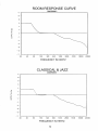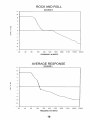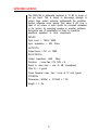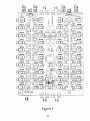
1
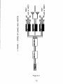
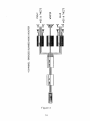
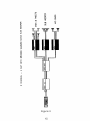
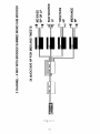
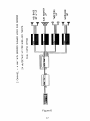
OWNER’S
MANUAL
OWNER’S MANUAL
MAQ-104 CAR AUDIO
OCTAVE EQUALIZER
A Division of Rockford Corporation
613 South Rockford Drive
Tempe, AZ 85281
602-967-3565
INDEX
. . . . . . . . . . . . . . . . . . . . . . . . . . . . Page 1
Introduction
Features
. . . . . . . . . . . . . . . . . . . . . . . . . . . . . . Page 1
Nomenclature
. . . . . . . . . . . . . . . . . . . . . . . . . . ..Page 2
. . . . . . . . . . . . . . . . . . . . . . . . . . . . . .Page 3
Installation
Equalization
. . . . . . . . . . . . . . . . . . . . . . . . . . . ..Page 5
Applications
. . . . . . . . . . . . . . . . . . . . . . . . . . . . .Page 8
Possible Equalization Curves. . . . . . . . . . . . . . . . . . . .Page 9-10
Specifications
. . . . . . . . . . . . . . . . . . . . . . . . . . ..Page 11
Possible System Configurations. . . . . . . . . . . . . . . . . . .Page 12-17
Warranty
. . . . . . . . . . . . . . . . . . . . . . . . . . . . . .Page 18
INTRODUCTION
Congratulations on your selection of the Hafler MAC-104
Octave Equalizer. You have acquired a product that will
greatly enhance the performance of your auto sound system. Because of the sophistication of this advanced
electronic device, we recommend that you thoroughly
understand the contents of this manual before operation
and installation
FEATURES
Full 4 channel operation maintains ability to fade.
> Single chassis provides straight forward installation
10 Bands per channel for optimal adjustment.
> + 12dB of boost and cut per band.
> Each channels flat position is located by a center click
in each potentiometer.
Defeat switching front and rear.
> Perfect for trouble shooting.
> Aid in vehicle curve adjustment
> Can be used for 2 channel dual curve installation
(See Figure 6)
Multi-Mode operation.
> 4 channel 4 way
> 2 channel 2 way
> 2 channel dual curve
Programmable remote turn-on delay circuitry.
> Switch selectable delay times from .5 to 4 seconds
> Remote in from source unit is delayed and then
passed on to the amplifiers.
> Provides a delay period for the stabilization of all
electronics prior to amplification.
> Eliminates turn on/off thump.
Gold plated RCA Connectors
1
Hinged top provides easy access to crossover modules.
> Detailed owner’s manual located conveniently inside
hinged top.
> Cosmetically "clean” look enhances any installation.
> Mounting holes concealed internally.
Output sensitivity adjustment.
> Insures compatibility with any radio or head piece.
> Independent adjustment per channel.
NOMENCLATURE
Refer to figure 1 for the location of the inputs, outputs,
potentiometers, and various switches used in the configuration of the MAQ-104.
Front/Rear defeat switch: These two switches will either
make the MAQ-104 circuitry active or bypass it completely.
See Figure 1 for active/defeat positions.
Delay switch: These dip switches
remote turn-on delay period.
are used to program the
Frequency band boost and cut: Each adjustment potentiometers on the MAQ-104 will allow you to boost by turning
any potentiometer clockwise, and cut by turning counter
clockwise.
WARNINGS
To prevent possible system damage, please follow the
guidelines below.
> Never connect or disconnect any component of the
sound system while power is applied to the system.
> Prolonged exposure to high sound pressure levels
can cause hearing impairment - please use common
sense when listening to your auto sound system.
2
INSTALLATION
The MAQ-104 is a precision piece of electronic equipment
and with proper installation will provide years of trouble-free
operation. The following steps will help to reduce the
amount of time and effort required to install the MAQ-104
> Consult a professional installer if necessary
> Mount the unit securely in a clean, dry location using
the four internal mounting holes. The four mounting
holes are located adjacent to the circuit board
> Make sure the installation does not interfere with the
normal operation of the vehicle
POWER CONNECTOR
The four power wires on the MAQ-104 should be connected
as follows:
Yellow - connect to the + terminal of the
battery.
Red - Connect to the remote turn-on lead from the
source.
Black - Connect to the chassis of the vehicle The ground
point in the car should be a piece of chassis m e t a l t h a t
is welded to the main body of the car. Painted surfaces
should be scraped or sanded before the ground lug is
bolted down, (Cover the bare metal area with paint or
grease to prevent rust.)
Blue - Connect to the remote turn-on leads of the amps
FUSES
The battery wire (yellow) is fused on the circuit board with
an AGC 1 amp fast blow fuse. The remote out wire (blue)
is also fused on the circuit board with an AGC 1/2 amp fast
blow fuse. In order to assure continued protection, replace
only with the proper fuse values. See Figure 1 for proper
fuse locations.
PROGRAMMABLE TURN-ON DELAY
The MAC-1 04 has the capability to delay the remote turn-on
voltage to the amplifiers by a period of up to 4 seconds.
This delay period is necessary in order to allow the signal
3
processing circuitry prior to the MAQ-104 sufficient time to
stabilize before power is applied to the amplifiers. This
results in minimum turn-on/turn-off thump.
.
To program the turn-on delay period, set the relay dip
switches as shown below:
TIME
1
2
0.5
1.0
2.0
4.0
ON
ON
OFF
OFF
ON
OFF
ON
OFF
FRONT/REAR DEFEAT SWITCHES
The switches in figure 1 are shown in the active position
(in the up position with the power connector on your upper
left.) By pushing the toggle down this defeats each respective front and rear channel.
FREQUENCY BAND BOOST AND CUT
On the MAQ-104 there are 10 bands of center frequency
boost and cut. By selecting a frequency noted on the PC
board you can boost or cut any band. Boost is accomplished by tuning the potentiometer clockwise. Cut is
done in reverse fashion counter clockwise. The flat position is noted by a center detent on each potentiometer
INPUT LEVEL SENSITIVITY
The MAQ-104 is designed to be used at pre-amp and radio
output levels only (500 to 750 mVRMS). Higher input levels
to the MAQ-104 may overload the circuitry and must be
attenuated.
OUTPUT SENSITIVlTY ADJUSTMENT
There are four output gain adjustment potentiometers on
the MAQ-104. The output levels must be set in such a way
as to not overdrive the amplifiers.
A proper adjustment can be achieved by adjusting both the
source unit and MAQ-104 output levels. If you find that your
4
over driving the amplifiers turn down the output levels of
the source and then fine adjust the MAQ-104.
EQUALIZATION
Response problems created by the audio environment (the
car’s acoustics) usually can be corrected with a good
quality equalizer that has flexible and precise adjustment.
The MAQ-104 provides this flexibility and precision.
Response problems created by poor system design must
be corrected at the amp and speaker level.
EQUALIZING WITH A REAL TIME
ANALYZER
For best resolution, a 30-band (1/3-Octave) Real-time
Analyzer (RTA) or a swept spectrum analyzer with 1/3-Octave resolution should be used. A lo-band, 1-Octave
resolution RTA will give decent results, but is harder to use.
Either RTA method will require a pink noise generator.
STEP BY STEP
1) Extend MAQ-104 input/output cables and B + , turn-on
and ground to a convenient location outside the vehicle.
(A kit is available from your Hafler dealer.)
2) Test the system to ensure proper function - “zero” all pots
and check level by switching the defeat switch quickly.
3) Position microphone and stand in car seat, head height,
ear level (preferably inside ear) with microphone facing
forward. Microphone placement will have a significant
effect on frequency response, and moving the microphone
around in the driver’s area will give a good idea of overall
response.
4) Calibrate RTA.
5) Input pink noise to MAQ-104 on channel corresponding
with microphone placement. Set volume level to 90-100
dB.
5
BE CAREFUL! PINK NOISE CAN HURT SPEAKERS AT
EXCESSIVE VOLUME. MAKE SURE VOLUME ON PINK
NOISE GENERATOR IS DOWN BEFORE TURNING ON.
6) Observe output response
7) Turn off pink noise and re-input source. Listen to system
with a piece of music you are familiar with. (NACA disc)
Does system sound like it looks? If not, reposition
microphone until system response looks like it sounds.
Major system problems, for instance large response “holes”
or “peaks”, should be solved by correcting speaker or
system problems. Trying to equalize out large response
errors (over 6 dB) will result in overdriven amplifiers and
speakers, and should not be attempted
8) Once microphone placement has been verified, reconnect pink noise.
9) Begin to equalize by first adjusting the frequency positions that need to be effected. Since adjacent bands interact with each other, you will need to go back and forth
between frequencies to get the best balance
10) Periodically verify curve by listening to your reference
music. Equalize one channel at a time. Compare your
“EQ’d” curve with the original response by switching defeat
switch If it isn’t getting better, return to zero and start
again.
11) Once one channel is correctly adjusted, the other
channel will come easy. Move the microphone to the
opposite side, change the pink noise channel, and equalize
for the same response.
12) Make any fine tuning adjustments while listening to both
channels simultaneously.
13) Reinstall MAQ-104
functioning.
into car. Listen to verify proper
SOME SUGGESTIONS:
>It is best to equalize one channel at a time. Trying to
set all four channels at once confuses which channel
is producing the results.
> If you can identify a response problem by ear, move
the microphone to a point that reveals the problem
Mike placement can have a very large effect on
6
response, and some microphone positions will
obscure problems instead of showing them.
> The audible effect of response problems is a product
of both the magnitude of the error and its width. A
9-dB “hole” one/third octave wide is less audible than
a 2-dB “dip” two octaves wide. Try for an average
response equally above and below the desired
response over each octave span.
> The human ear averages the overall sound-field
response by complex physiological and psychological processing. A single microphone only hears at
one point, which must be selected to represent as
closely as possible the overall sound field. Since
tonal perception is most influenced by the nearest
source, we usually equalized each side separately.
The mike is set up at the driver’s listening location,
facing forward, and the left channel is equalized
Then the mike is set up at the passenger’s location
and the right channel is set up to match the left. This
procedure usually gives good results
EQUALIZATION GOALS
The primary goal of the MAQ-104 is to produce a smooth
response approaching a desired curve, eliminating or
reducing peaks and valleys in our system response
A system can be equalized for a flat response but in most
cases this is a dry and flat response. The best equalization
is the one that fits your style of music For example: a curve
with the bass boosted would be more realistic to a Rock
and Roll type of person, where a partial boost in this section
would be more natural to Symphonic Music
Figures 2-5 show some typical “good-sounding” system
response curves. Curve “2” is a good general-purpose
goal. Curve “4” with increased bass will give more impact
on Rock-and-Roll, while “3” would sound more natural for
Symphonic Music. Curve ”5" illustrates reduced roll-off rate
in the mids and highs. These curves are only examples,
and the best curve is the one that suits your listening style
APPLICATIONS
4 CHANNEL OPERATION
4 Channel operation is accomplished by using all 4 inputs
and outputs. Figures 2-3 show typical hook up examples.
2 CHANNEL OPERATION
2 channel operation of the MAC-104 uses only 2 of the 4
inputs. Figures 4-5 show some typical examples.
2 CHANNEL X 2 OPERATION
(DUAL CURVE)
This is accomplished by feeding the source outputs into
both inputs of the MAQ-104. Next tie both the MAQ-104
outputs together. The dual curve option is then produced
by making either the front channels active and the rear
channels active. The reverse is also possible. See Figure
6 for hook up example.
This type of option is well suited for convertible cars that
have their hoods up or down. For those people that share
a car but have different listening styles, this dual option is
also nice.
NOTE 1: This option is only two channel operation.
NOTE 2: By having both front and rear active at one time
you will have little or no output.
8
SPECIFICATIONS
The MAQ-104 is deliberatdy restricted to 12 dB of boost or
cut per band. This is meant to discourage attempts to
correct large system response problemswith the equalizer.
System response errors greater than about 6 dB over a
span of an octave or more should be corrected elsewhere
in the system, by correcting speaker or amplifier problems.
Excessive use of equalization is likely to overdrive
amplifiers, speakers, or other components.
INPUTS
Input Level = 750mV RMS
Input Impedance = 20K Ohms
OUTPUTS
Output Level = 750 mV RMS
ELECTRICAL
Output Impedance =500 Ohms
Distortion = Less than .01% THD + N
Signal to noise ratio = over 90 dB (A-weighted)
Filter Q = 2 typical
Power Required = less than 1 amp at 12 volts typical.
PHYSICAL
Dimensions = 8.000H x 10.125W x 1.75D.
Weight = 3 Ibs.
11
WARRANTY
From 1 year from the date of purchase (The Warranty
Period), Hafler warrants that any unit which fails to function
properly under normal use due to a MANUFACTURING
DEFECT, when installed and operated according to the
Owner’s Instruction Manual enclosed with this unit, will be
repaired or replaced, at Hafler’s option, without charge to
you for parts or labor for the actual repair work.
Proof of purchase must be provided with the returned unit
to insure full benefit of the warranty period, for if not, Hafler
will be unable to honor the warranty, labor and pans will be
charged to you.
The product must be delivered within the warranty period,
transportation prepaid, to the Hafler Factory, or an
authorized Hafler warranty service station together with
evidence of date and place of original retail purchase
This warranty does not cover damage due to unauthorized
repair, nor does it cover damage due to improper shipping
by customer.
Hafler will pay for the cost of returning the repaired or
replacement product to you within the United States
This warranty does not cover any appearance item, any
accessories used in conjunction with the product, or any
damage to the product resulting from the alterations, accident, misuse or abuse.
This warranty does not apply if the parts or labor, which
would be otherwise provided without charge under this
warranty, are obtained from any source other than Hafler
or an authorized service center.
Hafler limits its obligation under any implied warranties
under state laws to a period not to exceed the warranty
period.
All product returned under warranty must be accompanied
by a return authorization number. RA numbers may be
obtained by phone at 602-967-3565. Defective product
must then be sent prepaid to:
HAFLER
613 South Rockford Drive
Tempe, AZ 65261
18
Dear Hafler Owner,
The gloss black insert on the face-plate of your new Hafler
equipment has been packaged with a removable protective coating. Please peel off this protective coating following installation.
When cleaning the face plate, we advise a soft cotton cloth
with a non-abrasive cleaner that is safe for Lexan and
painted surfaces. DO NOT use paper towels or any coarse
material to clean the face-plate as these materials may
scratch the insert.
We are sure you will enjoy your new Hafler product both
sonically and cosmetically for years to come.
The Hafler Team!
19