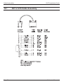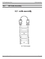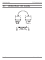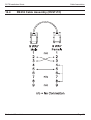
1
Downloaded from: http://www.guardianalarms.net
DVST Installation Guide
January 1996
DFT-0150
INSTALLATION GUIDE
Dedicated Micros UK Ltd.
11, Oak Street, Swinton, Pendlebury.
Manchester.
M27 4FL.
United Kingdom.
Direct Telephone: 0161 727 3241 Direct Fax: 0161 794 4464
Outside UK. Telephone: Int +(44) 161 727 3241 Fax: Int +(44) 161 794 4464
Dedicated Micros U.S.A. Inc.
11515 Sunset Hills Road, Reston, Virginia 22090, U.S.A.
Telephone: Int +(703) 904 7738 Fax: Int +(703) 904 7743
Dedicated Micros (Australia) PTY.
Unit 1, 30 Leighton Place, Hornsby NSW2077, Australia.
Telephone: Int +(612) 482 1857 Fax: Int +(612) 482 1647
Dedicated Micros (Asia) Ltd.
1 Tannery Road, #05-04/05 Cencon 1, Singapore 1334 .
Telephone: Int +(65) 741 0138 Fax: Int +(65) 741 0221
Dedicated Micros (Belgium) Ltd.
Interleuvenlaan 64, B-3001 Leuven, Belgium
Telephone: Int +(32) 16 40 12 28 Fax: Int +(32) 16 40 02 43
© Dedicated Microcomputers Group Ltd. 1995
All rights reserved. No part of this publication may be
reproduced or distributed in any form or by any means
without the prior written permission of the publisher.
Dedicated Micros Ltd
Page i
6 April 1995
DVST Installation Guide
Microcom ® is a registered trademark of:
Microcom Systems, Inc.
Gandalf ® is a registered trade mark of:
Gandalf Digital Communications Ltd.
Page ii
Dedicated Micros Ltd
DVST Installation Guide
Safety
Safety
Read Instructions - All the safety and operating instructions should be read before the unit is operated.
Retain instructions - The safety and operating instructions should be retained for future reference.
Heed warnings - All warnings on the unit and in the operating instructions should be adhered to.
Follow instructions - All operating and user instructions should be followed.
Cleaning - Unplug the unit from the outlet before cleaning. Do not use liquid cleaners or aerosol
cleaners. Use a damp cloth for cleaning.
Attachments - Do not use attachments not recommended by the product manufacturer as they may
cause hazards.
Water and Moisture - Do not use this unit near water - for example, near a bath tub, wash bowl,
kitchen sink, or laundry tub, in a wet basement, near a swimming pool, in an unprotected
outdoor installation, or any area which is classified as a wet location.
Accessories - Do not place this unit on an unstable stand, tripod, bracket, or mount. The unit may fall,
causing serious injury to a person and serious damage to the unit. Use only with a stand,
tripod, bracket or mount recommended by the manufacturer, or sold with the product.
Any mounting of the unit should follow the manufacturer’s instructions, and should use a
mounting accessory recommended by the manufacturer.
An appliance and cart combination should be moved with care. Quick stops, excessive
force, and uneven surfaces may cause the appliance and cart combination to overturn.
Ventilation - Openings in the enclosure are provided for ventilation and to ensure reliable operation of
the unit and to protect it from overheating. These openings must not be blocked or
covered. This unit should not be placed in a built-in installation unless proper ventilation
is provided.
Power Sources - This unit should be operated only from the type of power source indicated on the
manufacturer’s label. If you are not sure of the type of the power supply you plan to use
consult your appliance dealer or local power company. For units intended to operate
from battery power, or other sources, refer to operating instructions.
Grounding or Polarization - This unit may be equipped with a polarized alternating-current line plug
(a plug having one blade wider than the other). This plug will fit into the power outlet only
one way. This is a safety feature. If you are unable to insert the plug fully into the outlet,
try reversing the plug. If the plug should still fail to fit, contact your electrician to replace
your obsolete outlet. Do not defeat the safety purpose of the polarized plug.
Alternately this unit may be equipped with a 3-wire grounding-type plug, a plug having a
third (grounding) pin. This plug will only fit into a grounding-type power outlet. This is a
safety feature. If you are unable to insert the plug into the outlet, contact your electrician
to replace your obsolete outlet. Do not defeat the safety purpose of the grounding- type
plug.
Power-Cord Protection - Power-supply cords should be routed so that they are not likely to be
walked on or pinched by items placed upon or against them, paying particular attention
to cords at plugs, convenience receptacles, and the point where they exit from the
appliance.
Overloading - Do not overload outlets and extension cords as this can result in a fire or electric shock.
Object and Liquid Entry - Never push objects of any kind into this unit through openings as they may
touch dangerous voltage points or short-out parts that could result in a fire or electric
shock. Never spill liquid of any kind on the unit.
Dedicated Micros Ltd
Page iii
Safety
DVST Installation Guide
Servicing - Do not attempt to service this unit yourself as opening or removing covers may expose
you to dangerous voltage of other hazards. Refer all servicing to qualified service
personnel.
Damage Requiring Service - Unplug the unit from the outlet and refer servicing to qualified service
personnel under the following conditions:
(a)When the power-supply cord or plug is damaged.
(b)If liquid has been spilled, or objects have fallen into the unit.
(c)If the unit has been exposed to rain or water.
(d)If the unit does not operate normally by following the operating instructions. Adjust
only those controls that are covered by the operating instructions as an improper
adjustment of other controls may result in damage and will often require extensive work
by a qualified technician to restore the unit to its normal operation.
(e)If the unit has been dropped or the cabinet has been damaged.
(f)When the unit exhibits a distinct change in performance this indicates a need for
service.
Replacement Parts - When replacement parts are required, be sure the service technician has used
replacement parts specified by the manufacturer. A replacement lithium battery is
available from Dedicated Micros Ltd.
Safety Check - Upon completion of any service or repairs to this unit, ask the service technician to
perform safety checks to determine that the unit is in proper operating condition.
Coax Grounding - If an outside cable system is connected to the unit, be sure the cable system is
grounded.
UNPACKING - The shipping carton is the safest container in which the unit may be transported. Save
it for possible future use.
WARNING - TO PREVENT FIRE OR SHOCK HAZARD, DO NOT EXPOSE THIS EQUIPMENT TO
RAIN OR MOISTURE.
The lightning flash with arrowhead symbol within an equilateral triangle is intended to
alert the user of this equipment that there are dangerous voltages within the enclosure
which may be of sufficient magnitude to constitute a risk of electric shock.
The exclamation point within an equilateral triangle is intended to alert the user to the
presence of important operating and maintenance (servicing) instructions in the
literature accompanying the appliance.
Page iv
Dedicated Micros Ltd
DVST Installation Guide
Regulatory Notes
Regulatory Notes
FCC AND DOC INFORMATION
(U.S.A. and Canadian Models Only)
WARNING
This equipment has been tested and found to comply with the limits for a Class A digital
device, pursuant to part 15 of the FCC rules. These limits are designed to provide
reasonable protection against harmful intereference when the equipment is operated in
a commercial enviroment. This equipment generates, uses, and can radiate radio
frequency energy and, if not installed and used in accordance with the instruction
manual, may cause harmful interference to radio communications. Operation of this
equipment in a residential area is likely to cause harmful interference in which case the
user will be required to correct the interference at his own expense.
If necessary, the user should consult the dealer or an experienced radio/television
technician for corrective action. The user may find the following booklet prepared by the
Federal Communications Commission helpful: “How to identify and Resolve Radio-TV
Interference Problems”. This booklet is available from the U.S. Government Printing
Office, Washington, DC20402, Stock No. 004-000-00345-4.
This reminder is provided to call the CATV system installer’s attention to Art. 820-40 of
the NEC that provides guidelines for proper grounding and, in particular, specifies that
the cable ground shall be connected to the grounding system of the building, as close to
the point of cable entry as practical.
CE Mark
This product is marked with the CE symbol and indicates compliance with the European
Community EMC directive 89/336/EEC.
This mark indicates that this product meets the following technical standards.
• EN 55022 1987 - “Limits and Methods of Measurement of Radio Interference
Characteristics of information Technology Equipment”.
• BSEN 50082-1 - “Electromagnetic compatibility - Generic immunity standard
Part 1: Residential, commercial, and light industry”.
• IEC 801-2 1984, IEC 801-2 1991 - “Electromagnetic compatibility for
industrial process measurement and control equipment Part 2: Electrostatic
discharge requirements”.
• IEC 801-3 1984 - “Electromagnetic compatibility for industrial-process
measurement and control equipment Part 3: Radiated electromagnetic field
requirements”.
Dedicated Micros Ltd
Page v
Regulatory Notes
DVST Installation Guide
• IEC 801-4 1988 - “Electromagnetic compatibility for industrial-process
measurement and control equipment Part 4: Electrical fast transient/burst
requirements”.
A “ Declaration of Conformity ” in accordance with the above standards has been made
and is recorded at: Dedicated Micros Ltd., Pendlebury, Manchester, England.
Page vi
Dedicated Micros Ltd
DVST Installation Guide
Table of Contents
Table of Contents
1
Introduction
1.1
1.2
1.3
1.4
2
Unpacking the unit
2.1
2.2
3
Callback
Alarms feature
Freeze all alarms
No frozen images
Offline frozen alarm
Track last alarm
Installation
4.1
4.2
4.3
5
Items in packing
Packing the DVST
Operation
3.1
3.2
3.3
3.4
3.5
3.6
4
DFT-0150 Transmitter
Telemetry
Event monitoring (Alarm) option
Audio option
5.5
5.6
5.7
Dedicated Micros Ltd
1
1
1
1
3
3
3
5
5
5
6
6
6
6
7
Rear Panel connections
Fig: 1 Rear panel layout
Key to Fig: 1
Power inputs
7
37 way alarm connecton
Fig: 2 Alarm input/output connections
8
Setup
5.1
5.2
5.3
5.4
1
8
9
What you require
Setup using a PC
Remote setup
DVST commands
HELP
QUIT
RESET
VIEW
Define camera inputs
MAX=nn
COL=nn
MON=nn
Auxiliary port CAMnn=
3
AUX=
Define auxiliary ports 1,2,3
PORT=
9
9
10
10
11
11
12
Page vii
Table of Contents
6
Demonstration Mode
6.1
6.2
6.3
7
7.3
7.4
7.5
7.6
7.7
7.8
7.9
7.10
7.11
13
Demonstration mode
DEMO=
EXTCLK=
Demo cable
Fig: 3 Wiring details for demo cable
Connecting the demo cable
Single cable operation
Fig: 4 Demo Cable Connections
Modems
7.1
7.2
Page viii
DVST Installation Guide
PSTN connection (modem)
MODEM commands
MODEM=
MODEM
MBAUD=
MODEM2
PORT=
Modem configuration strings
MODSTR=
MOD2STR=
USER=...
SEND
DIAL=
Modem operation
Connecting a modem in direct mode
Call request
Call answer request
Call disconnect.
Configuration of modem in direct mode
Using a modem in ATMODE
Call request
Call answer request
Call disconnect
General settings for modems in ATMODE 23
All modems:
Synchronous modems:
Asynchronous modems:
MOTOROLA VFAST
Country specific settings
No dialtone
Transmission speed
Microcom V3242
Syncronous mode :
DIP switch settings synchronous operation
DIP switch settings asyncronous operation
Trailblazer
Async mode
OCTOCOM OSI 8196A
13
14
15
17
17
17
19
21
22
23
25
27
28
29
Dedicated Micros Ltd
DVST Installation Guide
8
Terminal Adapters
8.1
8.2
8.3
8.4
8.5
9
Table of Contents
ISDN connection (Terminal Adapter)
31
DUALISDN=
ISDN=
Connecting a terminal adapter in direct mode
32
Making a Call
Answering a Call
Call disconnection
Configuring a terminal adapter for direct mode operation
Gandalf TA1
33
Direct mode
ASCOM 5000 / CITAM
34
ATMODE
Fig 5: ASCOM internal dip switch settings (ATMODE)
X21
Fig 6: ASCOM internal dip switch settings (X21)
Dataflex TA
38
Leased Line Transmission
9.1
9.2
9.3
9.2
Leased line terminology
DVST set up for leased line operation
Lleased line operation
ASCOM 64000 baseband modem
10 Calls
10.1
10.2
10.3
10.4
31
39
39
39
40
41
43
Passwords
43
PASSWORD=
PASSn=
SPASSWORD=
On screen titling
SYSTEM=
TIME=
DATE=
TLPOS=
TDPOS=
Telephone number entries / connection commands
TELn=
TELn
TYPEn=
TIMER=
DIALCLR=
Callback
CALLBACK=
11 Images and Transmission
44
45
46
47
Screen display - periscope mode
11.1
Image size
47
Target image size =
Dedicated Micros Ltd
Page ix
Table of Contents
DVST Installation Guide
12 Alarms & Events
49
12.1
Purpose & intended use
49
12.2
Alarm connections
49
12.3
ALARM settings
49
ASYS=
AON=n
AOFF=n
ANOnn
ANCnn
Images transmitted on alarm
ATYPEn=
AOUT=
ALMODE=
ADIAL=n
13 Audio
13.1
13.2
53
Equipment required but not supplied
Fig: 7 End Panel Layouts
Connectint the DAL100
Microphone
Speaker
Power supply
DVST connections
Set port usage
Fig: 8 Microphone Connection
14 Cable Assemblies
14.1
14.2
14.4
14.5
14.6
Page x
X21 to V35 cable assembly
X21 cable assembly
V24 SYNC cable assembly
RS232 cable assembly (DVST-PC)
RS232 cable assembly (DVST-DAL)
53
54
55
56
57
58
59
60
15 Glossary
61
16 Returns Procedure
63
Dedicated Micros Ltd
DVST Installation Guide
1
Introduction
Introduction
DVST is the generic name for a range of products designed to store and transmit digital
pictures at a higher quality and speed than previously possible.
1.1
DFT-0150 Transmitter
The DFT-0150 (Digital Fast Transmission) transmitter will process the images from up
to sixteen cameras for transmission or reception over ISDN or PSTN telephone lines.
1.2
Telemetry
The DFT 0150 can control telemetry cameras at the local site using built in telemetry
equipment.
1.3
Event monitoring (Alarms)
The internal alarm verification system for DFT0150 transmitter allows the unit to monitor
and act on external events. This can freeze a picture from the camera that corresponds
to a specific alarm input. The unit will then transmit this picture to the receiving station
where the operator can acknowledge the event and take relevant action.
This versatile alarm interface is a light duty 16 input / 2 output unit.
1.4
Audio option
Audio transmission is available allowing two way, half duplex, (one way at a time)
communication. (Transmission medium must be 19200baud or faster)
Dedicated Micros Ltd
Page 1
Introduction
DVST Installation Guide
This page is intentionally blank
Page 2
Dedicated Micros Ltd
DVST Installation Guide
Unpacking the unit
2
2.1
Unpacking the unit
Items in packing
The unit should be carefully unpacked and the packing materials retained. Check that all
the contents on the following checklist are present:
2.2
q
DVST Unit
q
Power Lead with molded IEC connector
q
Rack mount conversion kit
q
Installation Guide
Packing the DVST
If the DVST is to be returned for repair or transported to another location the original
packing should be used.
The unit should first be wrapped in the polythene bag. The preformed end pieces are
then placed at either side of the unit which can then be placed inside the cardboard box.
The box should be firmly sealed using appropriate tape.
If the unit is to be returned for repair ensure a valid returns note is clearly written
on the side of the box.
Dedicated Micros Ltd
Page 3
Unpacking the unit
DVST Installation Guide
This page is intentionally blank
Page 4
Dedicated Micros Ltd
DVST Installation Guide
3
3.1
Operation
Operation
Callback
The callback feature allows an operator at a monitoring station to call a DFT0100
transmitter on site and configure the unit to automatically call them back, ensuring that
the telephone call is charged to the transmitting and not the receiving site.
On sending a callback request, the monitoring station disconnects and waits for the
transmitting site to call back. With callback enabled, connection time is approximately
twice that of normal connection time.
3.2
Alarms Feature
The alarm system for the DFT0150 transmitter allows the unit to freeze the pictures from
cameras that correspond with the alarm inputs that have been triggered. These pictures
are then transmitted to a receiving station where they can be acknowledged and the
relevant action taken.
On an alarm the transmitter will automatically call the telephone number stored in
telephone entry 0.
If this number is busy then it will call the number stored in telephone entry 1. The
maximum number of telephone entries can be set between 1 and 16.
If the fall back numbers are busy the transmitter will automatically keep calling between
telephone entries 0 and 1 until one becomes free. However the user can configure the
DFT0150 to automatically call upto four numbers unitl one becomes free.
Depending on how the transmitter has been configured, incoming alarms are handled in
different ways.
Dedicated Micros Ltd
Page 5
Operation
3.3
DVST Installation Guide
Freeze All Alarms
Each alarm activation stores the corresponding camera image and transmits the frozen
image to the receiver.
The frozen pictures with a record of the time, date and camera number will be stored in
memory until the alarms have been acknowledged.
3.4
No Frozen Images
No frozen images are sent on alarm. If several alarms ocour to trigger the machine to
dial, one shot from each will be sent in quick succession without any operator control.
Any alarms present whilst on line will be indicated on the receive unit display baseline.
3.5
Offline Frozen Alarm
The first alarm activation stores the corresponding camera image and transmits the
frozen image to the receiver.
3.6
Track Last Alarm
With this mode no frozen images are sent.
If several alarms ocour to trigger the machine to dial, one shot from each alarm will be
sent in quick succession without any operator control, following an intruder. Any alarms
present whilst on line will be displayed full screen and un frozen.
Page 6
Dedicated Micros Ltd
DVST Installation Guide
Installation
4
Installation
The DVST Transmitter is supplied as a wall mounted unit.
4.1
Rear Panel connections
The DVST Transciever uses BNC connectors for all video inputs and outputs. Other
data connections are made via standard D type connectors. The optional keyboard is
connected by a 9 pin D type female plug.
Fig: 1 Rear panel layout
WARNING: DO NOT CONNECT THE UNIT TO OTHER EQUIPMENT WITH POWER ON.
Key to Fig: 1
1
2
3
Cmaera Inputs
ISDN 1
ISDN 0
4
5
6
Dedicated Micros Ltd
Modem
AUX 1
AUX 2
7
8
9
AUX3
10 Alarm Inputs
13 ISDN
IIc Socket
11 Power Connection
Connection
Telemetry Out 12 Integral Dataflext TA Unit
Page 7
Installation
4.2
DVST Installation Guide
Power Inputs
The DVST Transmitter is powered via a standard mains IEC cable which plugs into the
rear panel. Power cable retaining clip prevents the cable from dropping out.
The power supply is self adjusting to the mains input and can accept a voltage from 90 to
260 volts.
Mains supply frequency can be either 50 or 60 cycles.
4.3
37 Way Alarm Connections
Fig: 2 Alarm input/output connections
Page 8
Dedicated Micros Ltd
DVST Installation Guide
5
5.1
Setup
Setup
What you require
Setup of the DVST DFT-0150 is undertaken using a PC (Personal Computer)
connected to the AUX0 port on the front panel.
To set up the DVST using a PC you will need the following:
A personal computer with an RS232 port.
A connection cable between the serial port of the computer and the serial port
(AUX3) of the DVST unit. (Details are in the cable section of this manual)
A suitable communications program for your PC that can operate at 9,600 baud.
i.e. Procomm.
5.2
Setup using a PC
Procedure:
Turn off the power supply to the DVST and the PC.
Connect the two units together using a serial cable.
Power up both DVST and the PC then start the communication program.
Make sure that the speed and protocol of the communications program are as
follows:
Baud Rate=9,600
Parity=None
Data Bits=8
Stop Bits=1
Local setup mode can be entered by typing “ +++<ret>” or for MCI commands <ESC>
M\Setup on the keyboard. The DVST commands will appear on the screen of the PC.
If a password has been set the screen will go blank and the prompt PASSWORD> will
appear on the screen and a valid password must be entered followed by pressing the
<ENTER> key. If this entered correctly the prompt CMD> will appear on screen. More
details on the operation of passwords appear later in this manual.
Typing HELP and pressing the <ENTER> or return key will list all the available DVST
commands. These are listed with brief descriptions to assist users familiar with set up of
the DVST. All these commands are explained in detail within the manual, and have been
grouped in a logical order to make set up of the DVST easy.
Typing VIEW and then pressing <ENTER> will list the present settings of the DVST. To
exit the SETUP mode type QUIT then <ENTER>.The DVST will then return to normal
operation.
Dedicated Micros Ltd
Page 9
Setup
5.3
DVST Installation Guide
Remote Setup
Remote DVST units can also be set up in the same manner as a local DVST. The same
procedure should be followed when the DVST is on line to a remote unit. When the
SETUP key is pressed the screen will go blank and the command prompt REM> will
appear on screen.
Proceed as for the local system.
Note:
A PC cannot initiate remote set up with the “+++” command.
5.4
DVST Commands
Most commands are typed in direct and terminated by pressing the <ENTER> key on a
PC.
HELP
Note:
Lists all commands available.
Paragraphs 4.6 onwards detail the command information listed by the help option and
have been grouped together in the logical order that should be used when setting up a
DVST system.
QUIT
Exits the SETUP mode.
This returns the DVST to normal operation. If a MODEM is connected
and the DVST is set to MODEM=ON the initialisation strings will be
sent to the MODEM.
RESET
Resets DVST to factory defaults
This command is used to completely reset the DVST system.
(All values are reset to their default values.)
Note:
These values are stored in an integrated circuit called an EEPROM. This is not
dependent on a battery backup and will retain its settings indefinitely without a power
supply.
VIEW
Display current DVST settings
This will display all the current DVST settings.
Page 10
Dedicated Micros Ltd
DVST Installation Guide
5.5
Setup
Define Camera Inputs
MAX=nn
Sets maximum number of cameras
(default, 8)
Range is 1 to 16.
Correct settings of this ensures that any receiving station does not
spend time trying to collect invalid camera inputs.
COL=nn
MON=nn
Set camera to Colour
Set camera to Monochrome
(default, all cameras set to colour)
Format is COL=01, COL=05 etc.
Format is MON=06, MON=15 etc.
It is important that camera inputs are correctly defined as colour or
monochrome.
CAMnn=
Set camera title nn to ...
(default, Camera 01=CAMERA 01 etc.)
Format is CAM01=FRONT DOOR
5.6
Auxiliary Port 3
The auxiliary port 3 on the DVST can be used for programming the DVST with a PC or
for generating printer reports. Protocol is RS232 8 characters, no parity, one stop bit,
default at 9,600 baud.
AUX=
Note:
Set AUX port usage:
TERM, PRINT, MCI, DTMF, ENG, NULL
(default, ENG)
TERM is for terminal operation, control by PC.
PRINT operates as a printer connection.
MCI is for machine control interface.
DTMF is used to echo telemetry codes at the port.
ENG is used to display debug.
NULL turns the port off.
Altering this command from a PC is valid, but after changing the setting the PC it will no
longer communicate with the DVST. The reason is that the port has now been assigned
a different task. .
Dedicated Micros Ltd
Page 11
Setup
5.7
DVST Installation Guide
Define Auxiliary Ports 1,2, 3
The auxiliary ports 1, 2, 3 on the DVST can be configured to operate with additional
equipment i.e. printers, telemetry equipment and PC based conrol systems (MCI).
PORT=
Set PORT usage,
(Each field entry is separated by a space. If the
commands are entered correctly the new settings will
be displayed):
<AUX PORT> <BAUD RATE> <PARITY>
<DATA BITS> <STOP BITS> <FORMAT>
(default settings )
AUX1 N 8 1 38400 PKT
AUX2 N 8 1 38400 DATA
AUX3 N 8 1 9600
ENG
AUX PORTAUX1, AUX2, AUX3
BAUD RATE1200, 2400, 4800, 9600, 19200, 38400
PARITYN (None) O (Odd) E (Even)
DATA BITS5, 6, 7, or 8
STOP BITS1 or 2
FORMAT
Aux1DATACharacter based data operation
PKTPacket based operation
BLKBlock data operation
NULLTurn off port
Aux2DATACharacter based data operation
NULLTurn off port
Aux3TERMTerminal operation
PRINTSerial printer connection
MCIMachine control interface
DTMFSend telemetry codes to port
ENGDisplay debug messages
NULLTurn off port
Example
PORT = Aux3<space>9600<space>N<space>8<space>1<space>Term <return>
Page 12
Dedicated Micros Ltd
DVST Installation Guide
6
Demonstration Mode
Demonstration Mode
This is provided to allow two DVST units to be connected back to back without the need
for connection to MODEMs or Terminal Adapters.
A special demonstration cable is used, details of this are explained later in the chapter.
6.1
Demonstration mode
DEMO=
Turn the demonstration mode ON / OFF
Turns the demonstration mode on or off. The demonstration mode is
quit if the power to the DVST is turned off.
Note: ISDN must be set to Direct Mode
Dedicated Micros Ltd
Page 13
Demonstration Mode
6.2
DVST Installation Guide
Demo Cable
This cable allows two DVST units to be connected back to back without the need for
connection to MODEMs or Terminal Adapters.
Fig: 3 Wiring details for demo cable
Tech Note:
This is a synchronous balanced transmission. Transmit and receive lines therefore
cross yet maintain polarity. The flying lead is used to source a clocking signal from the
MODEM port.
Page 14
Dedicated Micros Ltd
DVST Installation Guide
6.3
Demonstration Mode
Connecting the demo cable
Single cable operation
The cable connects PORT 0 on the transmit unit to PORT 0 on the receive unit. The
small flying lead connects to the MODEM port on the receive unit.
Fig: 4 Demo cable connections
Dedicated Micros Ltd
Page 15
Demonstration Mode
DVST Installation Guide
This page intentionally blank
Page 16
Dedicated Micros Ltd
DVST Installation Guide
7
7.1
Modems
Modems
PSTN Connection (Modem)
Connection to a PSTN telephone line is via a modem and modem port.
7.2
MODEM Commands
MODEM=
Sets MODEM operation, three parameters:
The MODEM= command controls three distinct parameters.
OFF
(default, OFF)
Tech note:
The reason is as follows; if set to ATMODE the DVST attempts to communicate with the
MODEM when starting up, exiting set up mode etc. The DVST will wait a set period of
time for replies before giving up. This will considerably slow the system if no MODEM is
attached.
DIRECT, ATMODE
(default, ATMODE)
The DIRECT mode is used if the MODEM has its telephone numbers
stored internally and the DVST does not pass telephone numbers for
dialling.
The ATMODE is most often used. The DVST passes numbers from
the dial menu to the MODEM which then initiates a call.
Dedicated Micros Ltd
Page 17
Modems
DVST Installation Guide
SYNC
The sync or synchronous mode relies on the modem generating clock
signals to the DVST.
MODEM
Modem switches from the command mode CMD> to allow direct
control of a connected MODEM. The speed of communication with the
MODEM will be as set with the MBAUD= command.
This is called transparent MODEM mode and is terminated by
pressing the ESCAPE or ESC key.
MBAUD=
Set MODEM port ASYNC baud rate.
(default, 19200)
9600, 19200, 38400
This command sets the speed of communication between the DVST
and the MODEM when AUX 1 is used for asynchronous mode. The
speed of communication in the Synchronous mode is determined by
the clock signal supplied by the MODEM.
ASYNC
In the asynchronous mode the MODEM controls the flow of data using
RTS/CTS signals.
MODEM2
Modem switches from the command mode CMD> to allow direct
control of a connected MODEM through AUX 1. The speed of
communication with the MODEM will be as set with the PORT=
command.
This is called transparent MODEM mode and is terminated by
pressing the ESCAPE or ESC key.
PORT=
AUX1, 19200, N 8 1, MODEM2
Refer Chapter Setup (Basic).
Page 18
Dedicated Micros Ltd
DVST Installation Guide
7.3
Modems
Modem configuration strings
All MODEMs need special configuration, depending on how the MODEM is to be used
and how the DVST will interact with it.
Standard MODSTR set ups configure the MINIT and SREG strings, the USER string is
left free for any extra configuration that may be needed.
MODSTR=
Set type of modem: FAST or SYNC
(default, FAST)
This setting (shortened form of MODem STRings) automatically sets
up the DVST to operate with one of the three recommended
MODEMs.
FAST
This sets the MINIT and SREG strings for correct synchronous
operation with the MOTOROLA 326x VFAST MODEM. The MODEM
configuration strings are set up as follows:
MINIT=AT&M1 &D2 &C1 *FLO *AA1 *DTO *OC1
SREG=ATS10=30S25=0
SYNC
This sets the MINIT and SREG strings for correct synchronous
operation with the MICROCOM 4232bis MODEM. The MODEM
configuration strings are set up as follows:
MINIT=AT&M1 &D2 \GO \EO E1 &C1 \JO
SREG=ATSO=1
MOD2STR=
Set type of modem: FAST, SYNC, ASYNC or ZYXEL
(default, )ASYNC
FAST
This sets the MINIT and SREG strings for correct synchronous
operation with the MOTOROLA 326x VFAST MODEM. The MODEM
configuration strings are set up as follows:
M2INIT=AT&M1 &D2 &C1 *FLO *AA1 *DTO *OC1
SREG2=ATS10=30S25=0
Dedicated Micros Ltd
Page 19
Modems
DVST Installation Guide
SYNC
This sets the MINIT and SREG strings for correct synchronous
operation with the MICROCOM 4232bis MODEM. The MODEM
configuration strings are set up as follows:
M2INIT=AT&M1 &D2 \GO \EO E1 &C1 \JO
SREG2=ATSO=1
ASYNC
This sets the MINIT and SREG strings for correct asynchronous
operation with the Trailblazer MODEM. The MODEM configuration
strings are set up as follows:
M2INIT=ATSO=1 &C1 &K3 E1 V1 &MO
SREG2=ATS7=60 S10=7 S37=7
~S50=255 ~S51=5 ~S52=1 ~S110=0 ~S104=0
ZYXEL (US Modems Only)
This sets M2INIT and SREG2 for the correct synchronous operation
with the ZYXEL modem. The modem configuration strings are set up
as follows:
M2INIT=AT&M1&D2&C1&H0
SREG2=ATS10=30 S0=1
USER=...
Available for user configuration
(Default, blank)
The USER string is for any extra commands that the user may need to
send to the modem in addition to the MINIT and SREG settings.
SEND
Send current modem configuration
This transmits the information contained in the MINIT, SREG and
USER strings to the MODEM.
Although this command can be issued from the command mode at any
time, it is also invoked at the termination of any call and when the
command mode is exited with the QUIT command.
Page 20
Dedicated Micros Ltd
DVST Installation Guide
DIAL=
Modems
Modem dial string
(default, ATDT)
This is the command that must precede all numbers that the MODEM
has to dial. Typically the MODEM will dial using either pulse or tone
dialling. This is dependent on the telephone exchange the MODEM is
connected to, most modern exchanges are able to accept tone dialling
which is faster than the older pulse dialling method.
For tone dialling: DIAL=ATDT
For pulse dialling: DIAL=ATDP
Tip:
Extra information can be linked to the above commands, internal exchanges that
require a “9" to be dialled to access outside lines can have this added to the dial string,
typically ATDT9.
7.4
Modem Operation
All modern modems respond to a set of “Hayes” commands. There are several
differences in these commands from manufacturer to manufacturer. It is important to
use the correct commands with each modem and not to attempt to use one
manufacturer’s set up with another manufacturer’s modem.
If possible modems should be linked to DVST in the synchronous mode. Some
modems, for example those using PEP (Packet Ensemble Protocol), can only be used
in the asynchronous mode.
Cables for connection to synchronous and asynchronous modems are different and are
not interchangeable. Refer to the Cable Assemblies chapter for further details.
Dedicated Micros Ltd
Page 21
Modems
7.5
DVST Installation Guide
Connecting a modem in direct mode
This mode uses a modem in a ‘dumb’ mode, and purely relies on the hardware control
lines. Telephone number selection, and all other configuration must be performed at the
modem.
The modem is controlled using DTR (Data Terminal Ready), and indicates it’s status
using DCD (Data Carrier Detect).
Note:
This mode is not recommended, easier operation is achieved in ATMODE.
Call request
A call is requested by making DTR active (high). At this point the MODEM dials it’s
stored number, and attempts to establish the call with the remote end. When the call
connect has been completed the modem raises it’s DCD line, confirming it is connected
with the remote location.
A call already being active is indicated by the DCD line being active (high) from the
MODEM.
Call answer request
If a call is incoming, the modem answers the call, establishes the physical link, and then
raises DCD to inform the DVST unit that a call is present. The DVST unit responds to this
by taking DTR active (high).
Call disconnect.
This is requested by dropping the DTR signal. A successful disconnect is confirmed by
the DCD line being dropped by the MODEM. In this mode the DTR line remains low.
Configuration of modem in direct mode
No configuration can be performed by the system, however the following are required of
the modem :
Select synchronous operation.
Dial stored number on low to high transition of DTR.
Disconnect on a high to low transition of DTR.
DCD must follow remote carrier.
Ignore DTR to answer.
Auto-answer. ( If required ).
No flow control enabled.
Page 22
Dedicated Micros Ltd
DVST Installation Guide
7.6
Modems
Using a modem in ATMODE
In this mode the Hayes set of commands is used, all of which begin with the letters AT.
Both call setup and configuration are performed using these commands.
The commands can be configured on the DVST unit in setup mode.
The modem is also controlled using DTR (Data Terminal Ready), and indicates it’s
status using DCD (Data Carrier Detect).
Call request
The DTR is normally active, unless the modem channel is turned off, or the unit is in
setup mode.
To dial a call the system sends the dial string (set by DIAL= in the DVST setup menu ) to
the modem, followed by the number selected.
For synchronous operation the modem switches to synchronous mode on connection.
When the call connect has been completed the modem raises it’s DCD line, confirming it
is connected with the remote location. A call already being active is indicated by the
DCD line being active (high) from the modem.
Call answer request
If a call is incoming, and the DTR line is high, the modem answers the call, establishes
the physical link, and then raises DCD to inform the DVST unit that a call is present.
Call disconnect
This is requested by a high to low transition on DTR. A successful
disconnect is confirmed by the DCD line being dropped by the modem.
In this mode the DTR returns high after a short delay.
7.7
General settings for modems in ATMODE
The modem is configured from the DVST unit using the following strings:
MINIT=general modem configuration.
SREG=typically used for setting of s-registers.
USER=optional string, typically for individual customisation.
DIAL=string used to dial, typically ATDT for tone dialling.
The configuration details stored in MINIT, SREG & USER are sent on power-up, leaving
setup mode, and on disconnecting a call. If a MODEM is not present a large delay will be
experienced while the system waits for replies from the MODEM. To avoid this the
command MODEM=OFF should be selected from the DVST setup menu. It is also
possible to transmit or send these values to the MODEM using the SEND command in
setup.
It is also possible to communicate with the modem directly using the MODEM
command.
Dedicated Micros Ltd
Page 23
Modems
DVST Installation Guide
MODEM Requirements
Although there are default settings for three MODEMs, other MODEMs can be
cofigured to operate with DVST.
As the settings vary from manufacturer to manufacturer there is not a set series of
commands that are guaranteed to work. The following tables detail possible
configurations, all should be checked against the MODEM manual. Before attempting
these suggested settings the MODEM should be reset to factory defaults with the
command AT&F or ATZ
The following settings are required as a minimum:
All modems:
Action required of MODEM
Possible AT settings
DCD (Data Carrier Detect, sometimes abbreviated to
CD) must be set to follow the carrier. This signal
indicates to the DVST that a connection to another unit
has taken place.
&C1
The call must disconnect on a high to low transition of
DTR (Data Terminal Ready).
Only answer a call if DTR is present.
&D2
Auto-answer may be set if required.
Echo commands.
S0=1
Check MODEM manual
Country specific
E1
Synchronous Modems:
Extra action required of Synchronous MODEM
Possible AT settings
Asynchronous mode must be set to dial the number
and the modem must switch to synchronous mode on
carrier detect.
&M1
Flow control must be disabled.
The modem should ignore RTS.
&K0
Check MODEM manual
&R1
Asynchronous Modems:
Extra action required of Asynchronous MODEM
Asynchronous mode must be enabled.
&M0
Flow control must be enabled on RTS/CTS.
&K3
Error correction enabled ( if needed ).
Note
Page 24
Possible AT settings
Refer to MODEM manual
It is strongly recommended that once the modem has been configured as above, it is set
in such a mode that this configuration is recalled automatically on power up. This will
help to ensure correct operation after a power failure. Consult you modem instructions
for details of how to achieve this.
Dedicated Micros Ltd
DVST Installation Guide
7.8
Modems
MOTOROLA VFAST
Cable required to connect to DVST: (25 to 25 - V24 SYNC)
When installing the VFAST MODEM the following procedure should be
followed:
Connect the MODEM and DVST as in the installation chapter.
Power up the DVST (leave the MODEM without power).
Enter the setup mode and configure the DVST for operation with the VFAST MODEM by
typing the command MODEM=ATMODE,MODSTR=FAST (default setting).
Power up the MODEM and wait for the self test to finish.
Type SEND then <ENTER>.
The DVST will program the MODEM.
It is good practice to store these values permanently in the MODEM.
Then the values will not be lost if power is removed from the MODEM.
To store these values proceed as follows:
User= AT&Y1&W1 <return>
Send <return>
Moden displays <save completed>
The MODEM will then always power up with the correct operational configuration.
Country specific settings
The answer on number of rings command *AA1 is not valid in some countries (France,
xx) and the MINIT string should be reprogrammed with the value *AA2.
The MINIT string is programmed as:
MINIT=AT&M1 &D2 &C1 *FLO *OC1 *DTO *DE12 *AA1
Dedicated Micros Ltd
Page 25
Modems
DVST Installation Guide
No Dialtone
In some cases the MODEM will not recognise the prescence of a dial tone from the
exchange. The following codes will allow blind dialling and if these are needed
permanently they should be followed by:
User=ATX3*BDO&Y1&W1
Where
ATX3 is Dial blind without presence of dial tone
*BD0 Wait two seconds before dialling
&W1 Store above settings in option 1
&W1 Power up using these settings
Note:
This feature is country specific and may not be available in some versions of the
MODEM’s software. Please refer to the literature supplied with your MODEM.
Transmission speed
The MODEM can be a little ambitious in setting the line speed. It is likely that a link will be
established at a higher speed than the line can support without an unacceptable level of
errors.
In these cases it may be necessary to limit the speed of transmission until a reliable point
is reached.
Maximum line speed may be set by the command:
AT*MXn
where the value for n equals following baud rate applies:
13 =28800
12 =26400
11 =24000
10 =21600
9 =19,200
8 =16,800
7 =14,400
6 =12,000
5 =9,600
4 =7,200
3 =4,800
2 =2,400
1 =1,200
0 =300
To limit the speed of transmission to 14,400 use AT*MX7. This could be stored in the
USER= string.
Page 26
Dedicated Micros Ltd
DVST Installation Guide
7.9
Modems
Microcom V3242
Cable required to connect to DVST 25to25 (Part No.AS-DVST-SYNC)
Syncronous mode :
&M1Dial async, switch on connect.
&D2Hangs up with on to off transition of DTR - needed for auto answer.
\G0Disables modem flow control.
\E0Do not echo data !
E1Echo commands.
&C1CD follows carrier.
\J0Turn off baud rate adjust.
DIP Switch Settings Synchronous Operation
Front panel switches
Dedicated Micros Ltd
Rear panel switches
Page 27
Modems
7.10
DVST Installation Guide
Trailblazer
Cable required to connect to DVST 9to25 (Part No. AS-DVST-ASYNC)
Async mode
Trailblazer in Conventional Command mode.
&C1CD follows carrier.
&k3RTS/CTS flow control.
E1Echo commands
V1Textual result codes
&M0Async mode
s7=60Wait 60 seconds for carrier.
s10=7Carrier loss to disconnect time.
s37=7Attempt to connect in PEP mode.
~s50=255Operate in PEP mode.
~s51=519200 bps operation.
~s52=1Modem hangs up on DTR, only autoanswer on DTR.
~s110=0PEP data compression disabled.
~s104=0Disable auto dialling.
Page 28
Dedicated Micros Ltd
DVST Installation Guide
7.11
Modems
OCTOCOM OSI 8196A
Cable required to connect to DVST 25to25 (Part No. AS-DVST-SYNC)
Manufacturer:
Octocom Systems, Inc.
One Executive Drive
Chelmsford,
MA 01824
USA
No DIP switches are used.
A single DATA push button on the front panel serves to unhook the
modem.
When the modem is unpacked and used for the first time the CD line
is held on. This means that the DVST unit believes that there is an
incoming call and waits for data.
Proceed as follows to clear this condition:
Wait for the DVST unit to time out
and then press <SETUP>
At the command prompt CMD> typeMINIT= <RET>
At the command prompt CMD> type SREG= <RET>
At the command prompt CMD> type USER=AT <RET>
At the command prompt CMD> type SEND <RET>
Wait for the information to be sent to the modem.
At the command prompt CMD> type MODEM <RET>
The unit will reply - Modem Mode
Type AT <RET>
The reply from the modem is “OK”
Type in the following,
AT&M1&C1&D2&K0&R1<RET>
The reply from the modem should be “OK”, if the reply
is “ERROR”, try again.
Type AT&W
The modem will now power up without the CD line held on.
Press the <ESC> key to exit modem mode.
At the command prompt CMD> type. MINIT=&M1 &C1 &D2 &K0 &R1.
&M1Dial async, switch to sync on connect.
&C1CD follows remote carrier.
&D2 Hangs up with on to off transition of DTR - needed for auto answer.
&K0Modem flow control is disabled.
&R0Modem iignores RTS, CTS is on when the modem is online.
Dedicated Micros Ltd
Page 29
Modems
DVST Installation Guide
This page intentionally blank
Page 30
Dedicated Micros Ltd
DVST Installation Guide
Terminal Adapters
8
Terminal Adapters
TA(s) or Terminal Adapters allow the DVST to communicate over digital ISDN
telephone lines.
8.1
ISDN Connection (Terminal Adapter)
Connection to an ISDN line is via a terminal adapter and Port 0. On systems using dual
ISDN lines both Port 0 and Port 1 should be connected.
The type of cable required to connect to the terminal adapter can vary.
DUALISDN=
...Sets dual ISDN support ON or OFF
(default, on)
ISDN=
...Sets ISDN for ATMODE, DIRECT, X21 mode
(default, ATMODE)
DIRECT
DIRECT mode relies upon the terminal adapter dialling a stored
number or a network only accessing a single remote point. Also used
for Demo mode (chapter 7)
ATMODE
ATMODE refers to Hayes AT dialling where the numbers to be dialled
are stored in the DVST dialling menu, also used for Dedicated Micros
Terminal Adaptor TA04
Dedicated Micros Ltd
Page 31
Terminal Adapters
DVST Installation Guide
X21
Uses X21 dialling for numbers in the DVST menu
Connection can be made in the direct mode, where the number to be called is stored in
the terminal adapter, or in the X21 dialling mode where the DVST passes the number to
be dialled to the Terminal Adapter, or ATMODE.
V35
V35=ON/OFF
Applicable in all modes (ATMODE, DIRECT and X21)
8.2
Connecting a terminal adapter in direct mode
This uses the signalling lines; C (control) and I (indicate), to respond to and initiate calls.
Making a Call
The DVST initiates a call by raising C
The TA then dials its stored number
When the call is connected the TA raises I
Call continues
Answering a Call
The TA indicates an incoming call by raising I
The DVST responds by raising C
Call continues
Call disconnection
The DVST ends a call by dropping C
The TA confirms disconnection by dropping I
Configuring a Terminal Adapter for direct mode operation
Note:
Page 32
As the control lines I & C are used to control calls, the following is required of the system:
Answer : C
Originate : C
Disconnect : C
Alerting : I
DCD/I : Delay
The above settings are the basic requirements. TAs have many other settings which
can affect transmission such as speed of call, type of call, circuit switch etc.
Dedicated Micros Ltd
DVST Installation Guide
8.3
Terminal Adapters
Gandalf TA1
Cable required 15 to 25 (2 of Part No. AS-DVST-TA1)
The Gandalf TA1 is a dual port unit capable of simultaneiusly using both ISDN B
channels on an ISDN2 connection.
The Gandalf has two X21 ports, PORT0 & PORT1. They must be configured as follows
for DIRECT connection:
Direct Connection
Configure the Gandalf as follows:
CALL MODE=CKT SWITCH AUTO
CALL TYPE=BOTHWAY
CALL SPEED=NEGOTIATE
ANSWER=C
ORIGINATE=C
DISCONECT=C
ALERTING=I
DCD/I=DELAY
Dedicated Micros Ltd
Page 33
Terminal Adapters
8.4
DVST Installation Guide
ASCOM 5000 / CITAM
ATMODE
Note:
Cables required - 2x 15 to 15 (Part No. AS-DVST-X21). Dip switch settings can be used
and should be set as follows:
Switch 3 selects the sub address, if used.
Fig 5: ASCOM internal dip switch settings (ATMODE)
Page 34
Step
Instruction
1
Using the pull handle, remove the
circuit board module from the Citam
5000
2
Adjust the dip switches as shown in
Figure 9
3
Press the select key four times so
that the legend ‘CONF’ appears on
the display.
4
Press the enter key once and it will
say ‘PRT1’, press the select key
twice it will say ‘TA’ , press the enter
key it will say ‘SHOW’.
5
Press and hold select until the
display reads ‘CHNG’, remove your
finger from the select key and press
the enter key, ‘INDB’ will be
displayed.
6
Press the enter key, the message will
be ‘ON’, use the select key to turn
this to ‘OFF’, then press the enter
key.
7
Hold the select key and press the
enter key, the display will return to
‘CONF’.
8
At ‘CONF’ press the enter key, the
display will read ‘PRT1’ for port 1.
Remarks
The Citam will now perform a self test.
On completion the display will read
ISDN.
This has turned of the in-band test
feature of the unit.
Dedicated Micros Ltd
DVST Installation Guide
Step
Instruction
9
Press the enter key, it will read
‘SHOW’. Hold the select until this
changes to ‘CHNG’, press the enter
key , display will then show ‘DIPS’ for
dip switch.
10
Press the enter key, it should read
‘INAC’ for inactive, press the select
key to change this to ‘ACTV’ for
active, press the enter key to return to
‘DIPS’.
11
Hold the select key down and press
the enter key, this will return unit to
‘CONF’.
12
Press the enter key and the display
will read ‘PRT1’, press the select key
to change this to port 2.
13
Press the enter key and ‘SHOW’ will
appear, hold the select key for three
seconds, the display will change to
‘CHNG’.
14
Press the enter key it will change to
‘DIPS’, press the enter key and it will
say ‘INAC’, press the select key and
‘ACTV’ will be displayed, press the
enter key and display will return to
‘DIPS’.
15
Hold the select key and press the
enter key, returning the display to
‘CONF’.
Terminal Adapters
Remarks
The unit has now had the dip switches
made active on both ports 1 and 2.
SEND CONFIGURATION STRING
16
Dedicated Micros Ltd
At the command prompt CMD> type
ISDN=ATMODE <RET>
DUALISDN=ON <RET>
ISDNSTR = CITAM <RET>
At the command prompt CMD> type
SEND <RET>
Wait for the information to be sent to
the modem. At the command prompt
CMD> type
ISDN0 <RET>
AT<RET>
AT&W<RET>,
<ESC>
ISDN1<RET
AT<RET>
Page 35
Terminal Adapters
DVST Installation Guide
AT&W<RET>
<ESC>
QUIT <RET>
These commands are entered using
Setup Mode on the DVST0200 unit via
a PC. Refer to Chapter para
The Citam is configured to operate on DVST.
X21
Cables required - 2x15 to 15 (Part No. AS-DVST-X21)
Fig 6: ASCOM internal dip switch settings (X21)
Note:
Dip switch settings can be used and should be set as follows:
Switch 3 selects the sub address, if used
Step
1
2
Instruction
Using the pull handle, remove the
circuit board module from the Citam
500
Adjust the dip switches as shown in
Figure 10
Remarks
The Citam will nowperform a self test
On completion the dispaly will read
ISDN
3
4
5
6
7
8
Page 36
Press the select key four times so
that the legend ‘CONF’ appears on
the display
Press the enter key once and it will
say ‘PRT1’, press the select key
twice it will say ‘TA’ , press the enter
key it will say ‘SHOW’
Press the hold select until the display
reads ‘CHNG’ remove your finger
from the select key and press the
enter key, ‘INDB’ will be displayed
Press theenter key, themessage will
be ‘ON’,use the select key to turn this
to ‘OFF’, then press the enter key
Hold the select key and press the
enter key, the display will return to
‘CONF’
At ‘CONF’ press the enter key, the
display will read ‘PRT1’ for port 1
This has turned off the in-band test
feature of the unit
Dedicated Micros Ltd
DVST Installation Guide
Terminal Adapters
Cont.
Step
Instruction
9
Press the enter key, it will read
‘SHOW’. Hold the select until this
changes to ‘CHNG’, press the enter
key, display will then show ‘DIPS’ for
dip switch
Press the enter key,it should read
‘INAC’ for inactive, press the select
key to change this to ‘ACTV’ for
active, press the enter key to return to
‘DIPS’
Hold the select key down and press
the enter key, this will return unit to
‘CONF’
Press the enter key and the display
will read ‘PRT1’, press the select key
to change this to port 2
Press the enter key and ‘SHOW’ will
appear, hold the select key for three
seconds, the display will change to
‘CHNG’
Press the enter key it will change to
‘DIPS’, press the enter key and it will
say ‘INAC’, press the select key and
‘ACTV’ will be displayed, press the
enter key and display will return to
‘DIPS’
Hold the select key and press the
enter key,returning the dispaly to
‘CONF’
10
11
12
13
14
15
Remarks
The unit has now had the dip switches
made active on both ports 1 and 2
The Citam is configured to operate on DVST.
Dedicated Micros Ltd
Page 37
Terminal Adapters
8.5
DVST Installation Guide
Dataflex TA
The Dataflex terminal adaptor
Cable 2 x 15 to 15 way (X21 Cable Assembly refer to page )
When connected to or supplied with a Dataflex Terminal Adaptor the DFT0150will
automatically configure itself for this type of operation. Ensure all terminal adaptor
conections are made BEFORE power up, on power up the DFT0150 will send its
configuration string to the terminal adaptor. The following is provided for information
only.
These commands are entered using Setup Mode on the DVST0150 unit.
SEND CONFIGURATION STRING
1
Page 38
At the command prompt CMD> type
ISDN=ATMODE <RET>
At the command prompt CMD> type
ISDNSTR =DATAFLEX <RET>
Wait for the information to be sent to
the modem.
At the command prompt CMD> type
DUALISDN=ON <RET>
SEND <RET>
ISDN0 <RET>
AT <RET>
AT&W <RET>
<ESC>
ISDN1 <RET>
AT <RET>
AT&W <RET>
<ESC>
At the command prompt CMD> type
QUIT <RET>
The Dataflex TA is now configured for use with the DVST0150.
Dedicated Micros Ltd
DVST Installation Guide
9
Leased Line Transmission
Leased Line Transmission
Leased line transmission is generally used when a dedicated or private line is available
to connect the transmit and receive units.
There are many different types of leased line, 2 wire and 4 wire, with many variants
depending on what is offered by the PTT companies.
Most conventional Modems can operate on leased lines although the cables will differ
from those used on a standard telephone connection.
Baseband Modems offer faster transmission rates over standard Modems and an
example using one of these is given at the end of this chapter.
9.1
Leased line terminology
In leased line terms the receiver or calling unit is set as ORIGINATE.
The transmit unit is set to ANSWER.
9.2
DVST set up for leased line operation
When leased line operation is selected, the type of transmission selected (via the X21 or
the V24 port) is determined by the dial type set in telephone number 0.
If telephone number 0 is set to MODEM, the V24 or Modem port will be used. If either
ISDN 0 or 1 is specified, X21 ports 0 or 1 will be used.
LEASED=
Dedicated Micros Ltd
Leased line operation, options are:
(default, OFF)
Page 39
Leased Line Transmission
DVST Installation Guide
ORIGINATE
The Receiver unit is set to originate.
ANSWER
The Transmitter unit is set to answer.
OFF
This disables the leased line feature.
9.3
Leased line operation
When leased line operation has been set up, the DVST will attempt to communicate with
a remote site when clocks are received. This does not require hardware handshaking.
If the line is broken for any reason, the units will attempt to reconnect and when
commuunication is restored will automatically establish video transmission of images.
The units can be disconnected (taken off line) by pressing the LINE key. Pressing the
LINE key again will establish image transmission.
Page 40
Dedicated Micros Ltd
DVST Installation Guide
9.4
Leased Line Transmission
ASCOM 64000 Baseband Modem
The am-64000 is a good alternative to using a conventional PSTN MODEM in leased
line mode.it also has a greater data transfer rate for short or private wire connections,
the speed is 64kbps for the AM-64000 and 128kbps for the AM-128000, the max
distance between the two units is 14 kilometres on a 0.64 mm cable or a -50 db loss.
Set Both Dvst Units In The Direct Mode
Using the cursor keys on the front of the ASCOM unit set the system up as follows.
SET UP TX OR MASTER END
RATE MENU64K
OPTION MENUX21
CONFIGURATION MENUMASTER MODE
HIGH RATE
X21 LOOPS OFF
BIT SYNC
64K MODE OFF
POWER 0 dBm
MENU UNLOCKED
SET UP RX OR SLAVE END
OPTION MENUX21
CONFIGURATION MENUSLAVE MODE
HIGH RATE
X21 LOOPS OFF
POWER 0 dBm
MENU UNLOCKED
Connect both units to the line and confirm that the status menu reads C=off and I=on.
This confirms the units are in communication.
Dedicated Micros Ltd
Page 41
Leased Line Transmission
DVST Installation Guide
This page intentionally blank
Page 42
Dedicated Micros Ltd
DVST Installation Guide
Calls
10
10.1
Calls
Passwords
Passwords can be set and used by the system. When a PASSWORD is set it provides
protection for the system at two points:
1) Whenever a remote system calls it must send the correct password, otherwise
no connection will be established.
2) Whenever the SETUP key is pressed, the password will be requested before
the setup mode is entered.
Method:
Enter SETUP mode is by pressing the SETUP key on either keyboard.
If a password has been set the screen will go blank and the prompt PASSWORD
will appear on the screen. At this point a valid password must be entered followed
by pressing the <ENTER> key. If this entered correctly the prompt CMD will
appear on screen.
PASSWORD=
Set system password to ...
The system password can be up to 10 alpha numeric, case sensitive,
characters. Once this has been set only calling units that have the
associated password linked to the telephone number can access the
system.
PASSn=
Set telephone entry n password to ...
Range is 0 to 19
This is linked to the designated telephone number and is the keyword
that will unlock the remote system that is being called. It may be up to
10 alpha characters in length.
Format: PASS4=BERLIN
In the above case the system called would have the password set to
BERLIN. Only then could the system be accessed.
Default: None set
Dedicated Micros Ltd
Page 43
Calls
DVST Installation Guide
SPASSWORD= Set SETUP password to ...
This feature allows an additional password to be allocated just to
provide security for the set up mode. This can be used to prevent a
remote user accessing the system and altering the settings.
Default: None set
Note:
To maintain security, passwords cannot be read back from the system. Care should be
taken to ensure passwords are not lost as this will require a new EEPROM chip to be
fitted to the DVST.
10.2
On Screen Titling
SYSTEM=
Set system ID string to ...
This is a 30 character title which appears on the front screen of the
DVST. When a transmitter sends to a receiver this title is transferred
from the transmitter and appears on the baseline of the receiving
monitor.
TIME=
Set current time in HHMM format
The time is based on the 24 hour clock. 4 digits must be entered.
DATE=
Set current date in DDMMYY format
Date is always set as a six figure format.
Two optional messages are superimposed on camera images sent from the transmitter.
The first is the camera title and the second is the time and date.
TLPOS=
Set camera title position
(default, 1)
When the images are transmitted the camera title appears at the top of
the screen. This setting adjusts the height of the camera title.
TDPOS=
Set clock screen position
(default, 11)
When the images are transmitted the time & date appears at the
bottom of the screen. This setting adjusts the height of the time & date
information.
Note:
Page 44
The range available for both TLPOS and TDPOS is from 1 to 11, 1 is at the top of the
screen and 11 at the bottom. Settings for TLPOS and TDPOS should be 2 numbers
apart to avoid overlap. Setting either value to 0 removes the text from the screen.
Dedicated Micros Ltd
DVST Installation Guide
10.3
Calls
Telephone Number Entries / Connection Commands
TELn=
Set telephone entry n to ...
(default, blank)
Twenty telephone numbers can be stored in memory.
Format: TEL2=01044617944965
If the MODEM or ISDN Terminal Adapter is to work in the DIRECT
mode, the entry can be left blank.
Telephone number 0 is the default number dialled when alarms are
used to initiate a call to another system. The fall back number if this is
engaged is always stored in telephone number 1.
Where a number is used with dual ISDN dialling it is automatically linked with that
number plus 10. Therefore Tel number 4 & 14 would be dialled if dual ISDN was
selected for that telephone number.
TELn
Set telephone entry n as current
This selects the number that will be dialled initially if the up/down keys
are not used to select another.
Format: TEL2
TYPEn=
Set telephone entry type to dial via ISDN0, ISDN1,
ISDNx2 (dual), or MODEM
(default, ISDN0)
Each of the telephone numbers can be linked to either a PSTN
MODEM or an ISDN terminal adapter.
This command determines which of the external ports (MODEM, ISDN
Port0, or ISDN Port1) will be used when a particular telephone number
is selected.
Format:
TYPE0=ISDN0
TYPE1=ISDN1
TYPE2=ISDN2
TYPE3=MODEM
TYPE4=MODEM2
Example: TYPE5=2
Sets Telephone entry 5 to ISDN2
Dedicated Micros Ltd
Page 45
Calls
DVST Installation Guide
TIMER=
Call connection timeout period
(default, 60 seconds)
This is the period of time that the DVST will wait while trying to connect
a call. This will vary depending on the type of call (ISDN or PSTN) and
as there may be a delay in establishing International calls, the timer
value should be increased.
DIALCLR=
10.4
...Sets time dial menu remains on screen
(default, 30 seconds)
Callback
This feature allows an operator to dial a remote unit and then have that unit
automatically call the operator back. This can be a useful security feature. The operation
of callback is as follows:
Local unit calls remote unit.
Call connects.
Local unit passes the dial menu number (0 to 9) that the remote unit will call back.
Call disconnects.
The local unit waits for a return call.
Remote unit waits for ten seconds then calls local unit.
Local unit answers and contact proceeds as normal.
CALLBACK=
Set call back ON or OFF
(Default, off)
When the callback feature is switched on the option appears on the
dialling menu to make either a normal call or a remote callback call.
Normal call is the default and this is highlighted. By using the left and
right arrow keys remote callback can be selected and deselected.
Note:
Page 46
Callback must be enabled on BOTH the transmit and receiving units
Dedicated Micros Ltd
DVST Installation Guide
11
Images and Transmission
Images and Transmission
Screen display - Periscope mode
CAMLO=Sets low resolution cameo operation:
Options are:
QUADHIHigh resolution quad size image
QUADLOLow resolution quad size image
CAMHISixteenth screen size high resolution
Default:
QUADLO
11.1
Image size
Target image size =
In the different screen modes of DVST each image is compressed to a target size and
then transmitted.
SIZEFHI=Set target size (K):FULL HI RES
SIZEFLO=FULL LO RES
SIZEQHI=QUAD HI RES
SIZEQLO=QUAD LO RES
SIZEMULT=MULTISCREEN
DUALFHI=As above but for dual isdn operation
DUALFLO=
DUALQHI=
DUALQLO=
DUALMULT=
Target Picture Sizes :
SIZEFHI =20000(20000 Maximum)
SIZEFLO =12000(12000)
SIZEQHI =8000( 8000)
SIZEQLO =4500( 4500)
SIZEMULT=2500( 2500)
DUALFHI =20000(20000)
DUALFLO =14000(14000)
DUALQHI =8000( 8000)
DUALQLO =4500( 4500)
DUALMULT=2500( 2500)
Dedicated Micros Ltd
Page 47
Images and Transmission
DVST Installation Guide
This page intentionally blank
Page 48
Dedicated Micros Ltd
DVST Installation Guide
12
12.1
Alarms & Events
Alarms & Events
Purpose & intended use
Alarm devices connected to DVST transmission products are intended to allow
verification and response to remote events.
12.2
Alarm Connections
Alarm connections are made via a 37 pin D type male connector which plugs into the
side panel of the DFT0150.
WARNING: The alarm outputs are light duty reed relay types and should not be used for switching
heavy loads.
12.3
ALARM Settings
ASYS=
Set alarm system ON or OFF
(default, OFF)
The alarm system is dormant until activated by the ASYS=ON
command.
When an alarm condition is detected the DVST transmitter dials stored
number TEL0 from the dial menu. If a connection cannot be made to
this number the unit dials stored number TEL1 from the dial menu. The
transmitter will continue calling until a connection is made and the
alarm is acknowledged from the receiver.
AON=n
AOFF=n
Enable alarm contact n
Disable alarm contact n
(default, all alarm contacts enabled)
By default all contacts are ON, or able to respond to contact closures
on the alarm input.
Alarm inputs that are not used should be set to off.
Dedicated Micros Ltd
Page 49
Alarms & Events
DVST Installation Guide
Each input can respond to a contact closure or a contact opening, or
respond to both.
ANOnn
Set contact nn normally open
ANCnn
Set contact nn normally closed
Images transmitted on alarm
The action taken on detection of an alarm is for the DVST unit to store a point of alarm
image, dial the telephone number stored in dial menu number 0 and transmit the image.
The resolution of alarm images, and the screen mode in which they
are transmitted can be selected with the following command:
ATYPEn=
HI Selects a High resolution alarm image
LO Selects a Low resolution alarm image
The alarm settings are displayed in the view mode as follows, (type
VIEW <ENTER> and press a key until the following display appears)
Page 50
Alarm Number
Input
Status
Type
Contacts
01: ALARM
02: ALARM
03: ALARM
04: ALARM
05: ALARM
06: ALARM
07: ALARM
08: ALARM
09: ALARM
10: ALARM
11: ALARM
12: ALARM
13: ALARM
14: ALARM
15: ALARM
16: ALARM
01
02
03
04
05
06
07
08
09
10
11
12
13
14
15
16
On
On
On
On
Off
Off
On
On
On
On
On
On
On
On
On
On
FULLHI
FULLLO
FULLHI
FULLLO
N/O
N/O
N/C
N/C
FULLHI
FULLLO
FULLHI
FULLLO
FULLHI
FULLLO
FULLHI
FULLLO
FULLHI
FULLLO
N/O
N/O
N/O
N/O
N/O
N/O
N/O
N/O
N/O
N/O
Dedicated Micros Ltd
DVST Installation Guide
AOUT=
Alarms & Events
Set alarm outputs AUTO / MANUAL
(default is AUTO)
The two alarm contacts can be configured for automatic or manual
operation.
AUTO
In automatic mode relay 1 acts as a line indicator and closes whenever
the DVST is on line.
MANUAL
In manual mode the AUX1 key on the local unit controls relay 1 on the
remote unit, this works as a momentary contact. AUX2 on the local unit
controls relay 2, which works as a toggle on / off (latching) control.
ALMODE=
...Set Alarm operation mode
NOFRZ/OLNFRZ/ FRZALL/TRKLST
(default, OLNFRZ)
NOFRZ
No freeze mode - No frozen images are sent. If several alarms ocour
to trigger the machine to dial, one shot from each will be sent in quick
succession without any operator control. Any alarms present whilst on
line will be indicated on the receive unit display baseline.
OLNFRZ
Offline alarm freeze - Only freezes the first alarm image and then
transmits this image to the receiver. Subsequent alarms incoming
while the uniit is transmitting to a receiver are flagged on the baseline
but are not frozen, nor do they need to be acknowledged.
FRZALL
Freeze all alarm images - All alarm images are frozen. All must be
acknowledged by the receiving station before the alarm can be
cleared.
TRKLST
Track last alarm - No frozen images are sent. If several alarms ocour to
trigger the machine to dial, one shot from each alarm will be sent in
quick succession without any operator control, following an intruder.
Any alarms present whilst on line will be displayed full screen and un
frozen.
Dedicated Micros Ltd
Page 51
Alarms & Events
ADIAL=n
DVST Installation Guide
Set number of telephone entries to use in alarm
condition 1 / 2 /3 / 4
(default, 2)
By default DVST transmitter dials stored number TEL0, if a connection
cannot be made to this number the unit dials stored number TEL1 on
the menu. With ADIAL=3 the DVST transmitter dials the stored
numbers TEL0, TEL1, TEL2 until a line answers.
Page 52
Dedicated Micros Ltd
DVST Installation Guide
Audio
13
Audio
The Digital Audio Interface ( DAL100 ) is a sound unit for the DVST range of products
working on an intercom basis i.e. push-to-talk. Microphone and speaker connections
are provided together with volume control and indicators for power, transmit, receive
and line error.
Fig: 7 End Panel Layouts
13.1
Equipment required but not supplied
The following lists equipment you will need to complete your installation of the DAL100
audio unit.
Dedicated Micros Ltd
q
Microphone with automatic gain control and complete with push-totalk switch and 3.5mm jack connector.
q
Speaker capable of handling a 2W into 8 Ohm input.
Page 53
Audio
13.2
DVST Installation Guide
Connecting the DAL100
Microphone ( refer to fig. 7 )
Connect the 3.5mm jack plug of the microphone into socket on end panel. Connect the
microphone press-to-talk lead to pins 1 and 9 of a 15way male connector and plug into
socket on end panel,
Fig: 8 Microphone connection
Speaker ( refer to fig. 8 )
Connect the 3.5mm jack plug of the speaker to the SPEAKER OUT socket.
Power Supply ( refer to fig. 8 )
Connect the power supply to the socket marked PWR on the end panel.
DVST Connection ( refer to fig. 8 )
Using the 9 way to 9 way cable connect the DAL100 unit to port AUX1 on the DVST.
(Details are in the cable section of this manual)
Set Port Usage ( refer to SETUP para 5.7 )
Port Aux1 on the DFT0150 sould set to the following:
PORT = AUX1 38400 N 8 1 PKT
Page 54
Dedicated Micros Ltd
DVTS Installation Guide
14
Cable Assemblies
Cable Assemblies
The following pages detail cable assemblies with connectors for use with Dedicated
Micros rang of DVST transmitters and transceivers. The cables are fully screened for
EMC compatibility.
For prices and availability please contact our Sales Departments at the addresses
below.
Northern UK Sales
Dedicated Micros Ltd
Pendlebury Industrial Estate, Bridge St, Manchester, M27 1FJ,
United Kingdom
Tel: 0161-794-4965 Fax: 0161-728-4142
Outside UK : Int +(44) 161-794-4965 Fax: Int +(44) 161-728-4142
Southern UK Sales
Dedicated Micros Ltd
3 Cannon Court, Warren Farm, Stratford Road,
Wolverton Mill, Milton Keynes MK12 5NS
Tel: 0908-225199 Fax: 0908-225197
In the United States
Dedicated Micros Inc.
11515 Sunset Hills Road, Reston, Virginia 22090, U.S.A.
Tel: Int +(1) 703-904-7738 Fax: Int +(1) 703-904-7743
In Australasia & the Far East
Dedicated Micros (Asia) PTE Ltd
1557 Kepple Road, #02-03 Singapore 0208
Tel: +(65) 227-3923/27 Fax: +(65) 227-4869
Dedicated Micros (Australia) PTY
1, Tannery Road, #05-04/05 Cencon I, Singapore 1334,
Tel: Int +(65)-741-0138 Fax: Int +(65)-741-7743
In France, Germany & Benelux
Dedicated Micros (Belgium) Ltd
Interleuvenlaan 64, B-3001 Leuven, Belgium
Tel: Int +(32)-16-40-1228 Fax: Int +(32)-16-40-0243
Dedicated Micros Ltd
Page 55
Cable Assemblies
14.1
Page 56
DVTS Installation Guide
X21 to V35 Cable Assembly
Dedicated Micros Ltd
DVTS Installation Guide
14.2
Cable Assemblies
X21 Cable Assembly
Dedicated Micros Ltd
Page 57
Cable Assemblies
14.3
Page 58
DVTS Installation Guide
V24 Sync Modem Cable Assembly
Dedicated Micros Ltd
DVTS Installation Guide
14.4
Cable Assemblies
RS232 Cable Assembly (DVST-PC)
Dedicated Micros Ltd
Page 59
Cable Assemblies
14.5
Page 60
DVTS Installation Guide
RS232 Cable Assembly (DVST-DAL)
Dedicated Micros Ltd
DVST Installation Guide
15
Glossary
Glossary
DVST
Digital Video Storage and Transmission
ISDN
Integrated Services Digital Network - A digital telephone system capable of
transmitting data, speech, images and text.
PSTN
Public Subscriber Trunk Network - The standard telephone system used for
speech and fax communication.
Speed of Update
The time taken to refresh a single picture.
Software
Compression
Video data compression achieved by computer program processing.
Hardware
Compression
Video data compression taking place in specialised purpose built microchips.
k bytes
Measurement expressing the size of digital computer memory
k bits per
second
Measurement expressing the speed at which data can be transmitted.
Compression
Taking standard video signals and reducing these into compact digital data.
Decompression
Taking digitally compressed DVST information and restoring this to normal
video images.
Complete
compression
Each time the picture is transmitted, or stored to memory, the entire picture is
compressed.
Conditional
Updating
Update only the parts of the picture that have changed. The first time the
picture is transmitted the entire picture is compressed. Thereafter only the
parts of the picture that change are transmitted.
DAT
Digital Audio Tape, the new technology for recording digital information on a
special tape cassette. Massive storage can be achieved in a very small
package.
MODEM
MOdulator/DEModulator used to connect the DVST unit to a standard
telephone line.
Terminal
Adapter
Used to connect the DVST to an ISDN digital telephone line.
Dedicated Micros Ltd.
Page 61
Glossary
DVST Installation Guide
This page intentionally blank.
Page 62
Dedicated Micros Ltd.
DVST Installation Guide
Returns Procedure
16
Returns Procedure
In the Event of Difficulty
In the event of a fault, first approach your dealer or distributor. Dedicated Micros
operates a Technical Support Group where most technical problems can be solved over
the telephone. The addresses of Dedicated Micros are listed on the front page of this
manual.
If, for what ever reason, this is not possible, the unit can be returned directly to a
Dedicated Micros Repairs Department. In this event please follow the returns procedure
as detailed below to avoid delay.
Photocopy the EQUIPMENT RETURN ADVICE. Contact the Customer Services
Department to obtain a returns number.
The following information must be available to give to the Customer Services
Department when requesting a returns number.
q
Model type
q
Serial number
q
Full Account/Invoice address or Return Address if different
q
Contact name
q
Fax number and Telephone number
q
Customer order number - for repair cost not exceeding £100
q
Full description of the fault
Previous returns number(s) (if applicable)
q
If the unit is rack mounted, the rack mount kit must be removed before the unit is packed.
Wrap the unit in the original polythene bag. Fit preformed end pieces at either side of the
unit.
If the unit is not returned in it’s original packing, Dedicated Micros Repair Department
will automatically re-box the unit, and there will be a charge of £11.75 inc VAT.
Mark the return number, obtained from the Customer Services Department, clearly on
the outside of the box. Return the unit to the address on the front page of this manual, a
completed copy of the EQUIPMENT RETURN ADVICE must be sent with the unit.
If the unit crosses a national boarder, enter Airway Bill number on the copy of the
EQUIPMENT RETURN ADVICE and fax Dedicated Micros for the attention of the
Despatch Department. This will avoid any delays in returning the unit after it has been
repaired.
Dedicated Micros Ltd
Page 63
Returns Procedure
DVST Installation Guide
Notes:
Dedicated Micros tries to maintain a fast turnaround procedure for repairing equipment,
incomplete or inaccurate documentation may result in delay.
If the unit is not under warranty a charge will be made for the repair.
If the unit has it’s warranty void, due to misuse or damage, the Repairs Department will
contact the account customer to advise cost.
Upon examination of the unit if the repair cost is likely to exceed £100, the Repairs
Department will contact the account customer for authorisation before work is
undertaken.
Repairs not exceeding £100 will automatically be carried out and invoiced on the official
order number stated by the account customer on the EQUIPMENT RETURN ADVICE.
Page 64
Dedicated Micros Ltd
DVST Installation Guide
Dedicated Micros Ltd
Returns Procedure
Page 65
Returns Procedure
Page 66
DVST Installation Guide
Dedicated Micros Ltd