1
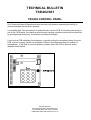
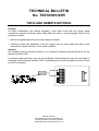
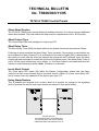
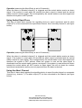
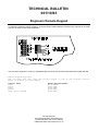
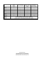
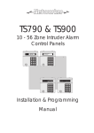
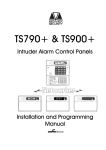
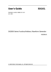
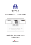
Technical Bulitin Contents
SD1 CALL ACKNOWLEDGEMENT
2
TS400 CONTROL PANEL
3
TSD401 CONTROL PANEL
4
TSD402 CONTROL PANEL
5
TS510 AND REMOTE KEYPADS
6
TS700 CONTROL PANEL
7
TS790 / TS900 SOFTWARE VERSION 2.2 AND ALL VERSIONS PRIOR
9
TS790 & TS900 CONTROL PANELS
10
TS2200 CONTROL PANELS
13
PROGRAMMING OF MENVIER DIGITAL COMMUNICATORS
14
DC54 AND DC58 DIGITAL COMMUNICATORS (PULSE DIALING)
16
DC54 AND DC58 DIGITAL COMMUNICATORS (EARTHING REQUIRMENTS)
17
LINE FAULT MONITORING
18
ENGINEERS REMOTE KEYPAD
19
TSPCI TO TSDCI CONVERSION
20
MILLENNIUM DATE CHANGE
21
LINELOAD COMPATIBLE MODEMS
22
PRINTER COMPATIBILITY
23
NACOSS CODES OF PRACTICE NACP14
24
CPA6 MKII & ACPO POLICY
26
TECHNICAL BULLETIN
SD1/001/93
SD1 CALL ACKNOWLEDGEMENT
Most of the queries we receive for the SD1 Speech Dialer relate to the acknowledgment
procedure This Technical Bulletin should clarify all aspects of the function, both for the enduser and the installer.
At the end of its message the SD1 sends an audible “beep” which must be answered within 2
seconds using the tone generated by pressing the [8] button on a standard telephone. On
hearing the [8] tone the SD1 immediately sends a second “beep” which must also be
answered in the same way. If successful a multi-tone confirmation signal is heard , if not then
the message is repeated with the acknowledgment “beeps” again at the end.
POINTS TO NOTE:
1. The SD1 will not acknowledge signals from Pulse Dialing telephones or those with
short tones. Check all recipients phones by calling them and getting them to press
the [8] button . If a series of clicks is heard (or the tone cannot be sustained by
holding down the button) then a Tone Dial Simulator will be needed to acknowledge
the SD1 messages (see below for details).
2. No harm is done by not acknowledging the message as the unit simply repeats the
message 5 times and then aborts the call.
3. The procedure is fairly fast and should be practiced by all the recipients under test
conditions. The [8] button must be pressed within 2 seconds each “beep” and should
be held down for between ½ to 1 ½ seconds. If either tone is not “seen “ by the SD1
the message is repeated again.
TONE DIAL SIMULATORS
For the acknowledgment procedure the SD1 “looks” for any tone between 600Hz and 1400Hz.
This is supplied most reliably by the [8] button used for DTMF dialing although other buttons
may work if pressed accidentally. I the recipients phone cannot produce a suitable tone then a
Tone Dial Simulator musty be used. These are available from many high street electrical
stores and also from specialist suppliers such as RS (stock code 252-841) and Maplins (stock
code CK252C).
Menvier Security
Kenn Road Clevedon Avon BS21 6LH
Tel 01275 870078 Fax 01275 343453
E.Mail http//:www.menviersecurity.co.uk
TECHNICAL BULLETIN
No. TS400/001/8/95
TS400 CONTROL PANEL
Battery Charging Voltage
Following recent requests from customers regarding the higher than normal charging voltage
of the TS400, the product has now been modified so that the nominal charging voltage is
13.6V (this now falls in line with the rest of the Menvier product range). However, it must be
made clear that even with a charging voltage of 14.1V the system and battery will continue to
function without concern. All TS400 control panels after serial number 97I25000 will have the
battery charging voltage set to 13.6V.
Battery Cut-Off Voltage
The TS400 also features a battery cut-off circuit which cuts off the charging voltage when the
battery voltage drops below 8.0V. On some installations this has caused problems if the mains
supply has failed for longer than 8 hours, as the battery will drop below the 8.0V threshold and
will not re-charge when the mains supply is restored. All TS400 control panels after serial
number 97K30000 will have the battery cut-off voltage lowered to 4.0V.
If you have any queries about this technical bulletin, please contact the Technical Support
Dept. at the address below.
Menvier Security
Kenn Road Clevedon Avon BS21 6LH
Tel 01275 870078 Fax 01275 343453
E.Mail http//:www.menviersecurity.co.uk
TECHNICAL BULLETIN
No. TSD401/001/3/95
TSD401 CONTROL PANEL
Symptom
When the TSD401 is triggered into an alarm condition, the dialler is activated and the unit will
proceed to dial the first telephone number. If a valid passcode is entered whilst the unit is
dialling, there is a remote possibility that the dialler may subsequently dial incorrectly.
Solution
To check whether this has ever occurred, play-back any of the recorded messages and if a
continuous tone is superimposed over the original message, the dialler may not dial correctly.
If this is the case, proceed as follows:
1. Remove all power from the system (mains and battery), then re-apply all power.
2. Select 'Speech Dialler' programming and re-record all messages.
3. Re-program all stored telephone numbers to 'Pulse' dial (see page 17 of the User Manual)
and exit 'Speech Dialler' programming.
However, if the message does not have a continuous tone superimposed over it, simply
perform step 3 of the above action.
All TSD401's after serial number '97F12100' will not require the above action.
Menvier Security
Kenn Road Clevedon Avon BS21 6LH
Tel 01275 870078 Fax 01275 343453
E.Mail http//:www.menviersecurity.co.uk
TECHNICAL BULLETIN
TSD402/001
TSD402 CONTROL PANEL
Our Technical Support Department have received one instance regarding the facility to
record messages on the above product.
It is possible that if the microphone is pushed firmly onto the PCB, the housing can touch on
one of the PCB tracks, the resulting short thereby causing a problem which can be identified
by a background “humming” sound when recording messages.
If you have a PCB exhibiting this symptom, try gently pulling the microphone away from the
PCB, a piece of paper can act as a suitable insulator (see diagram below for location of
microphone). If this fails to cure the problem, please return the PCB to Menvier at the
address shown below.
Menvier Security
Kenn Road Clevedon Avon BS21 6LH
Tel 01275 870078 Fax 01275 343453
E.Mail http//:www.menviersecurity.co.uk
TECHNICAL BULLETIN
No. TS510/001/4/95
TS510 AND REMOTE KEYPADS
Problem
On some installations with remote keypads, it has been found that the control panel
sometimes responds incorrectly when using either the main or remote keypad. Some of the
symptoms include:
Spurious keypad bleeps from the control panel or remote.
Customer enters their passcode to set the system, the exit timer starts then after a few
seconds the system will return to the unset condition.
Solution
The problem may be solved by fitting a 0.1uf capacitor between terminals E and C on the
Remote Interface PCB.
If screened cable has been used on the installation, the braiding must also be connected to
terminal E on the Remote Interface PCB. The braiding at the remote keypad must be cut back
and NOT connected.
Menvier Security
Kenn Road Clevedon Avon BS21 6LH
Tel 01275 870078 Fax 01275 343453
E.Mail http//:www.menviersecurity.co.uk
TECHNICAL BULLETIN
TS700/002
TS700 CONTROL PANEL
Menvier Technical Support have received queries regarding the facility to wire exit terminator
buttons per ward. The following will solve up to 2 exit terminator buttons. If you require more
then you will need to consider installing a TS790 / TS900 Control Panel.
The TS700 was developed several years ago and one of its limitations is that once a ward
has set, any unset wards will revert to timed exit. With this in mind it will be necessary to
change the setting modes for all part sets to timed exit and to set the exit time to 199 sec
(max).
Wiring
Any exit terminators fitted to the system will need to wired in parallel to the same zone.
Panel output 1 or 2 (switched -ve) must be programmed as zone mimic for the zone the exit
terminators are wired into. For example if the exit terminators are connected to zone 8,
program panel output (1 or 2) to type 47 (zone 8 mimic).
The programmed output needs to be wired through a 2K2 resistor to a zone that will be used
as the exit terminator for a different ward (e.g. zone 7).
Zones 7 & 8 must be programmed to the type ET (exit terminator) and assigned to the
respective ward.
Operation
When either exit terminator button is pressed the output activates, this then activates the
other zone programmed as exit terminator, which will set the area that is in exit mode.
NOTE
The settle time should be set to 5 seconds or higher and the exit terminator must not be
pressed and held as this may cause a set fail condition.
Menvier Security
Kenn Road Clevedon Avon BS21 6LH
Tel 01275 870078 Fax 01275 343453
E.Mail http//:www.menviersecurity.co.uk
Menvier Security
Kenn Road Clevedon Avon BS21 6LH
Tel 01275 870078 Fax 01275 343453
E.Mail http//:www.menviersecurity.co.uk
TECHNICAL BULLETIN
TS790 & TS900 No. 002 /02/95
TS790 / TS900 Software Version 2.2 and all versions prior
Problem
If a keyswitch zone has been programmed to operate Ward B, the Ward B attribute will be
removed after 14 days.
Solution
Either re-program the keyswitch to another Ward or set the `TEST TIME' to 00.
This problem has been corrected by the release of software Version 2.3, which was issued on
the 17/02/95.
Menvier Security
Kenn Road Clevedon Avon BS21 6LH
Tel 01275 870078 Fax 01275 343453
E.Mail http//:www.menviersecurity.co.uk
TECHNICAL BULLETIN
No. TS900/003/11/95
TS790 & TS900 Control Panels
Alarm Abort Feature
The TS790 & TS900 control panels fitted with software version 3.2 or above have an additional
alarm abort method. This new method will help meet the requirements of the ACPO policy.
Abort Output Type
The 'Abort Output' has been assigned to output type 071.
Abort Delay Timer
The Abort Delay Timer (028) has been added to the system timers and operates as follows:
Following an alarm condition the Abort Delay Timer is started. If the system is unset before the
timer expires the Abort Output (071) is activated and the Alarm Output (005) is deactivated. If
the system is unset after the timer has expired the outputs are NOT affected. Once the Abort
Output has been activated it is reset the next time the system is set. If the Abort Delay Timer is
set to 199 the timer is effectively set to infinite, i.e., the Abort Output is activated whenever the
system is unset following an alarm. Note: The timer is in seconds.
Invert Abort Output
The 'Clear alarm O/P' option (05) within the System Configuration options has now been
removed, as this is now covered by the new abort feature. Option 05 is now 'Invert Abort O/P'
and is used to invert the operation of the abort output type 071.
Using Alarm Restore
This is probably the simplest form of alarm abort as it requires no change to the signalling
device, however the device must report restore on channel 3 (see figure below).
Menvier Security
Kenn Road Clevedon Avon BS21 6LH
Tel 01275 870078 Fax 01275 343453
E.Mail http//:www.menviersecurity.co.uk
Operation (assuming the Abort Delay is set to 90 seconds)
When the alarm is activated channel 3 is triggered and the central station receive an alarm
signal. If the system is unset within 90 seconds the alarm output is cleared and the central
station receive a restore signal. This is interpreted by the central station as an abort signal and
therefore the system is NOT policed.
Using limited Open/Close
This form of alarm abort requires the signalling device to report open/close and the abort
output (071) to be connected to the open/close channel, this is normally channel 4 (see figure
below).
Operation (assuming the Abort Delay is set to 90 seconds)
When the alarm is activated channel 3 is triggered and the central station receive an alarm
signal. If the system is unset within 90 seconds the abort output is activated and the central
station receive an open signal. This is interpreted by the central station as an abort signal and
therefore the system is NOT policed. When the system is next set the abort signal is
deactivated and the central station receive a set signal. If the system is unset without an alarm
present the central station will NOT receive an open signal, this will cut down the number
open/close transmissions as they are only reported when the alarm is aborted.
Using the Abort Channel
This form of alarm abort requires the signalling device to report the abort signal on a separate
channel (e.g., channel 7). The abort output (071) is then connected to this channel (see figure
below).
Menvier Security
Kenn Road Clevedon Avon BS21 6LH
Tel 01275 870078 Fax 01275 343453
E.Mail http//:www.menviersecurity.co.uk
Operation (assuming the Abort Delay is set to 90 seconds)
When the alarm is activated channel 3 is triggered and the central station receive an alarm
signal. If the system is unset within 90 seconds the abort output is activated and the central
station receive an abort signal on channel 7. The system is therefore NOT policed.
Menvier Security
Kenn Road Clevedon Avon BS21 6LH
Tel 01275 870078 Fax 01275 343453
E.Mail http//:www.menviersecurity.co.uk
TECHNICAL BULLETIN
No. TS2200/001/12/95
TS2200 CONTROL PANELS
Menvier products have a facility whereby if the user is forced to unset a system under duress, it is possible to
generate a silent alarm which is totally undetectable by the intruder. To generate this "Duress" alarm, simply
unset the system by entering the passcode with the first two digits reversed.
For example, if the system is usually unset with the code 2468, simply enter 4268 to generate a duress alarm.
If it is required to disable this facility for a particular user, simply ensure that the passcode for that user has the
first two digits the same, e.g., 2268. Alternatively, it is possible to disable the duress facility for the entire
system. This can be done using the following sequence:
1. Enter the Engineer's passcode, the display will read "ALTER SYSTEM PROGRAM".
until the display reads "USE DIAGNOSTICS".
3. Press followed by and the display will read "ALTER SOFT SWITCHES"
4. Press and the display will read "SOFT SWITCH 1 <x>" where x will be ON or OFF.
5. Keep pressing until the display reads "SOFT SWITCH 8 <OFF>"
6. Press and the display will read "SOFT SWITCH 8 <ON>".
7. Press followed by . Keep pressing until the system returns to the unset condition.
2. Keep pressing
Menvier Security
Kenn Road Clevedon Avon BS21 6LH
Tel 01275 870078 Fax 01275 343453
E.Mail http//:www.menviersecurity.co.uk
TECHNICAL BULLETIN
NO. DC58/002/05/95
Programming of Menvier Digital Communicators
Objective
To distinguish the differences between NVM chips and programming method for all Menvier
digital communicators.
New Products
Menvier Security Ltd. have released three new digital communicators into the UK market,
these are:
DC54 (Plug-on/stand-alone 4 channel digicom)
DC58 (Plug-on/stand-alone 8 channel digicom)
DC58M (Plug-on 8 channel digi-modem)
PP5 (Programmer)
Old Products
The following items are no longer being manufactured:
DC3 (Plug-on 8 channel digicom)
DC3M (Plug-on 8 channel digi-modem)
DC28 (Stand-alone 8 channel digicom)
PP1/PP2 Kits (Programmer)
Programming
The table below shows which programmer is compatible with each product.
Product
PP1
PP2
DC3
DC3M
DC28
DC54
DC58
DC54
TS900 remote
& NETEKI
PP5 *
Note:- The NVM chip used in the new range of communicators is incompatible with the old
range of communicators and visa versa. The programming must be completed in accordance
with the above table.
Menvier Security
Kenn Road Clevedon Avon BS21 6LH
Tel 01275 870078 Fax 01275 343453
E.Mail http//:www.menviersecurity.co.uk
* Menvier Security will release the new PP5 programmer in July 95. NVM chips for the new
range of communicators can be programmed by the installation company using the standard
TS900 remote keypad (TS900.REM) and Interface lead (NETEKI).
NVM Device Types
All Menvier digital communicators are supplied with the NVM chip fitted, the device type used
is as follows:
The DC3, DC3M and DC28 all use device type: 24C44P
The DC54, DC58 and DC58M all use device type: 24LC01B
Both devices may be purchase from Menvier Security Repairs Department.
Further Assistance
For more information on any of above please contact Menvier Technical Support at Clevedon
on 01275 870078.
Menvier Security
Kenn Road Clevedon Avon BS21 6LH
Tel 01275 870078 Fax 01275 343453
E.Mail http//:www.menviersecurity.co.uk
TECHNICAL BULLETIN
No. 001/3/95
DC54 and DC58 Digital Communicators
Old Pulse Dial exchanges
Between 90 and 95%of telephone exchanges in the UK are the modern digital type, this type
of exchange accepts Pulse or Tone dialling formats and offers the users access to 'BT
Network Services' (Three-way calling, Call Diversion etc.). The remainder of the exchanges are
the older Pulse dial type and are normally found in rural areas of the UK. British Telecom are
actively changing the older type of exchanges for the more modern digital type. To find out
what type of exchange is in operation in your area, contact BT for advice.
In order for the DC54 or DC58 to work correctly on the older type exchanges the telephone
numbers MUST be programmed to Pulse dial, this will disable Three-way calling, as it is not
available on this type of exchange. The numbers are programmed as follows:
1. Ensure the display shows the selected telephone number, e.g., 'TELEPHONE NO.1'
2. Press the key and the display will show a `P' in the first character position.
3. Now enter the telephone number of the central station, e.g., 01811234567 when entered
the display will show `P01811234567'.
4. Press the key to accept the telephone number and repeat for telephone numbers 2 and
3, if appropriate.
If the DC54 or DC58 NVM is to be programmed by Menvier Security, please put a `P' in the
first box for each telephone Number on the NVM Programming Form (Back page of Installation
and Programming Manual).
Menvier Security
Kenn Road Clevedon Avon BS21 6LH
Tel 01275 870078 Fax 01275 343453
E.Mail http//:www.menviersecurity.co.uk
TECHNICAL BULLETIN
No. 002/1/96
DC54 AND DC58 DIGITAL COMMUNICATORS
Earthing Requirements
There has been several comments from intruder alarm companies that they have been docked
points on a NACOSS inspection for not having the digital communicator connected to earth.
The British Standards state that the digital communicator must be connected in accordance
with the manufacturers instructions. Both the DC54 and DC58 do NOT require an earth
connection. The protection is provided from the BT master socket in accordance with BABT.
Menvier Security
Kenn Road Clevedon Avon BS21 6LH
Tel 01275 870078 Fax 01275 343453
E.Mail http//:www.menviersecurity.co.uk
TECHNICAL BULLETIN
GEN/001/93
LINE FAULT MONITORING
Different digicoms use various methods of Line Fault monitoring. This technical bulletin will
describe the various methods available, but will not address remote line monitoring as used on
Direct Line systems or REDCare.
LINE VOLTAGE MONITOR:
This monitoring method is used on older products and merely checks that a healthy line
voltage is present on the telephone line. This voltage is nominally 50 volts, which drops to
below 35 volts when a parallel handset is taken off hook, and will drop to 0 volts if the line is
cut. With newer, digital exchanges, it is possible to detect line voltage even on an inoperative
line.
The DC54 / DC58 / DC58M digital communicators signal off hook and cut line as a line fault
when selected as HI security.
When selected as low security the DC54 / DC58 / DC58M will only signal line fault on a cut
line.
RINGING IN MONITOR:
This technique continually checks for presence of ringing to detect whether an attempt is being
made to "jam" the phone line.
This type of monitoring is also used on the DC54 / DC58 / DC58M digital communicators in
addition to the Line Voltage Monitor.
TEMPORARY OUT OF SERVICE:
This technique offers the highest security of the three methods in that it seizes the line at
predetermined intervals, seizes the line and dials all but the last digit of the recipient's
telephone number and tests for the number unobtainable tone. This type of monitoring is used
on the DC54 / DC58 digital communicators in addition to the Line Voltage monitor and the
Ringing In Monitor. The line test interval period can be selected between daily to fortnightly, or
can be disabled.
Line Fault monitoring is only necessary when a bell delay time is programmed into the control
panel.
THREE WAY CALLING
When the DC58 / DC58M is triggered the unit checks for incoming ringing or off hook. The
digicom then sends a “Recall “ signal which is detected by the exchange as a request for a
new line. With a new line available the DC58 / DC58M then attempts to connect with the
Central Station.
Menvier Security
Kenn Road Clevedon Avon BS21 6LH
Tel 01275 870078 Fax 01275 343453
E.Mail http//:www.menviersecurity.co.uk
TECHNICAL BULLETIN
001/10/93
Engineers Remote Keypad
To attach an engineer's remote keypad to a TS700 TS790 TS900 TS2500 connections are required to the PCB
plug JP2, as shown in the following diagram:
The connector required is a 7 way 0.1" pitch Molex type connector such as RS Components part number 479-080
Remote Keypads Required:
The following list will show the correct keypad to use on the relevant control
panel or digicom for programming.
Control Panel
TS700
TS790
TS900
TS2500
DC54/ DC58 / DC58M
Remote Keypad Needed
TS700 REM
TS900 REM
TS900 REM
TS900 REM
TS900 REM
Menvier Security
Kenn Road Clevedon Avon BS21 6LH
Tel 01275 870078 Fax 01275 343453
E.Mail http//:www.menviersecurity.co.uk
TECHNICAL BULLETIN
No. PCI/001/06/96
TSPCI to TSDCI Conversion
The following modification shows how to convert a standard TSPCI module so that it can be used with a DC58M
modem. This will allow the DC58M to be connected to PC instead of a proprietary modem unit. In order to use
the DC58M in the mode, the Lineload software must be version 2.01 or higher.
1.
2.
3.
4.
5.
6.
7.
Remove all crimps from shell.
Move blanking pin from position 5 to position 2.
Connect green wire to position 7.
Connect white wire to position 8.
Connect black wire to position 1.
Connect red wire to position 3.
Add power supply, *Diode and link as shown above.
Menvier Security
Kenn Road Clevedon Avon BS21 6LH
Tel 01275 870078 Fax 01275 343453
E.Mail http//:www.menviersecurity.co.uk
TECHNICAL BULLETIN
ALL PRODUCTS
MILLENNIUM DATE CHANGE
Menvier Technical Support have received queries regarding the millennium date change and
its affect on the control panels
All of the NETWORKER (TS700 / TS790 / TS900 / TS2500) range of panels will NOT be
affected by the year 2000 as they do not store any year in their dates.
The only panels that store the year in the date are the TS2200, TS2000 and CPA6. These
panels have been tested and DO NOT have a problem. The date rolls over to 1st Jan 2000.
Control Panel
Explanation
TS700
No Year Stored Only Day / Month
TS790
No Year Stored Only Day / Month
TS900
No Year Stored Only Day / Month
TS2500
No Year Stored Only Day / Month
TS2200
Changes from year 1999 to 2000
TS2000
Changes from year 1999 to 2000
CPA6
Changes from year 99 to 00 (see note)
TS800
No Year Stored Only Day / Month
TS5160
No Year Stored Only Day / Month
TS600
No Year Stored Only Day / Month
TS360
No Year Stored Only Day / Month
Note
Although all variants of CPA6 software change over from 1999 to 2000 only version STD2.1
and above allows the engineer/master user set the date with the a year range of 00 - 99. All
other variants such as A51AE will not allow the engineer/master user to set the year below
82 i.e. the panel will only accept dates between 82 - 99.
Menvier Security
Kenn Road Clevedon Avon BS21 6LH
Tel 01275 870078 Fax 01275 343453
E.Mail http//:www.menviersecurity.co.uk
TECHNICAL BULLETIN
LINELOAD COMPATIBLE MODEMS
The following list has been compiled to assist Lineload Software users in deciding which
modem to use. We have found the best success with external modems, as internals or voice
modems can be more difficult.
Recommended :-
Zoom 14.4XE External Modem
Zoom V34XE Fax Modem
Pace Linnet V34
Others Compatible :-
Intertext IX FaxModem
Octocom OSI8224A
Pace Linet 32
Pace Microlin
Pace Mobifax 144
US Robotics PCMCIA 2496
Dowty Quattro SB2422
If you already have a modem which is compatible at V21 (300 BAUD) and would like to use
the Lineload Software we can try to assist in configuring a custom setup string for your
particular modem but this is not always possible.
Others NOT Compatible:US Robotics 14.4VI
US Robotics 28.8 Voice / Fax Internal Modem
US Robotics PCMCIA 28.8 Modem
Motorola 28.8
Pace Microlin 33.6
NOTE:
All of the above modems are now obsolete (bar the Pace Linnet V34) but may be available
from your computer supplier as old stock.
We are currently working on evaluating other manufacturers modems and we will keep you
informed of our findings.
Alternative Method
It is possible to use a DC58M as the Modem for you computer. To do this you need to use a
DCI lead connected from you computer to the DC58M, then from the DC58M to the
telephone socket. This will then act as a normal 300 baud (V21) external modem.
Part No’s
TSDCI Lead
TSDC58M
General Communications Interface Lead
DC58M Digi/Modem
Menvier Security
Kenn Road Clevedon Avon BS21 6LH
Tel 01275 870078 Fax 01275 343453
E.Mail http//:www.menviersecurity.co.uk
TECHNICAL BULLETIN
GEN/1/93
PRINTER COMPATIBILITY
The following table defines printer compatibility between Menvier products.
CONTROL PANEL
CPA6 PRINTER
SERIAL PRINTER
TS500
N/A
N/A
TS510
N/A
N/A
TS700
YES
YES, WITH MPA
TS790
YES
YES, WITH MPA
TS900
YES
YES, WITH MPA
TS800
YES
YES, WITH MPA
CPA6
YES
NO
TS2000
NO
YES, WITH TS2000.SI
TS2200
NO
YES, WITH MPA
The communications protocol to the Serial Printer is:
4800 baud, Odd parity, 1 start bit, 2 stop bits, 8 data bits
Menvier Security
Kenn Road Clevedon Avon BS21 6LH
Tel 01275 870078 Fax 01275 343453
E.Mail http//:www.menviersecurity.co.uk
TECHNICAL BULLETIN
NACOSS CODES OF PRACTICE NACP14
The following is intended to inform the you about the requirements of NACP14 and its affect on
you and the compatibility of MENVIER's range of control panels and accessories.
The following paragraph is taken from NACP 14
2.1.1 Facilities To Aid Filtering-Out Of False Calls
All alarm systems within the scope of practice shall either:
(a) have means to indicate to the alarm receiving centre whether the alarm
system is set or unset;
OR
(b) be capable of generating a secondary signal to indicate to the alarm receiving
centre that the alarm system has been mis-operated.
In the case of alarm systems coming into operation on or before 31 December
1995 implementation of the above is deferred until 31 December 1996.
2.1.2 Means Of Completion Of Setting.
For all new alarm systems within the scope of this code of practice , coming into
operation on or after 1 January 1996 the completion of the full setting procedure
shall be achieved by means which involve positive action on the part of the
keyholder.
Translating the above into English, you will have to do the following on all new systems and
upgrade existing systems by 31 December 1996:
1. Send an open / close signal to the central station
OR
Send the Central station an Abort Signal.
2. Fit exit terminator buttons or final exit shunt locks to all new installations.
NOTE.
Any system fitted with a REDCARE must send open / close signal as the central
monitoring station will not police a no-response during the open state.
What must be appreciated is with the number of installations going in, the number of calls that
the central station are going to be processing will go through the roof. The answer would be to
only send the signal when needed which would be the ABORT signal. But you say how can my
existing jobs signal abort when the panel does not have the facility. The answer is to fit a
Menvier Abort Module which would be able to interface to your older / other control panels and
create an abort output for you.
Menvier Security
Kenn Road Clevedon Avon BS21 6LH
Tel 01275 870078 Fax 01275 343453
E.Mail http//:www.menviersecurity.co.uk
Abort
Signal
Exit Terminator
Open / Close
Signal
Restore of
Alarm Signal
TS510
û
_
_
_
TS700
û
_
_
_
TS790
_
_
_
_
TS900
_
_
_
_
TS800
û
_
_
_
TS2200
û
_
_
û
ABORT
Module
This is compatible with any panel capable of
giving a open / close signal and an alarm signal
Menvier Security
Kenn Road Clevedon Avon BS21 6LH
Tel 01275 870078 Fax 01275 343453
E.Mail http//:www.menviersecurity.co.uk
TECHNICAL BULLETIN
CPA6/001/08/96
CPA6 MKII & ACPO POLICY
There seems to be some confusion as to whether the CPA6.MKII can comply with the new ACOP policy. This is
because the SET output de-activates on starting entry procedure on most versions of CPA6 MKII software.
However software version STD2.21 has a correctly operating SET output and also RESTORES the Alarm output
on UNSET (alarm Abort)
STD2.21 software can be fitted to the CPA6 MKII providing that the memory board has 2 memory chip sockets
(1x28 pin and 1x24 pin). Although the upgrading of chips should be fairly strait forward the system will require
full reprogramming.
Software version STD2.21 is available as an upgrade item from the repairs department and any enquires as to
the availability or prices should be obtained through them.
Menvier Security
Kenn Road Clevedon Avon BS21 6LH
Tel 01275 870078 Fax 01275 343453
E.Mail http//:www.menviersecurity.co.uk