1
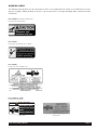
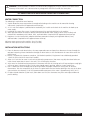
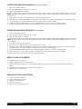
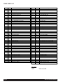
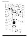
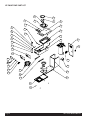
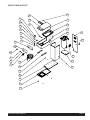
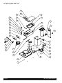
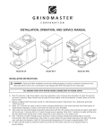
AUTO-SERIES BREWERS Installation, Operation, and Service Manual TABLE OF CONTENTS Warning Labels .............................................3 Water Connection .........................................4 Installation Instructions ..................................4 Coffee Preparation Procedures .......................5 Brew Volume Adjustment ..............................5 Brew Basket Rail Adjustment ..........................5 Spare Parts List .............................................. 6 Model AT-2W/AT-2WE Model AT-AP/AT-APE Water Tank Assembly Drawing .......................7 AT-2W/AT-2WE Drawing ................................8 AT-AP/AT-APE Drawing...................................9 AT-3WR/AT-3WRE Drawing ..........................10 AT-TC/AT-TCE Drawing .................................11 Troubleshooting Guide ................................12 Component Replacement Instructions ..........13 Prior authorization must be obtained from Grindmaster Corporation™ for all warranty claims. Model AT-3WR/AT-3WRE Model AT-TC/AT-TCE Grindmaster Corporation™ 4003 Collins Lane Louisville, Kentucky 40245 USA (502) 425-4776 (800) 695-4500 (USA and Canada only) (800) 568-5715 (Technical Service only) FAX: (502) 425-4664 www.grindmaster.com © Grindmaster Corporation, 2007 PRINTED IN THAILAND 0307 Form # BW-340-01 Part # 73254 WARNING LABELS The following warning labels were on your dispenser when it was shipped from the factory. They should remain on your dispenser in good, readable condition at all times. If one of your labels is missing or damaged, order a replacement label immediately. Part # 71509 (for warmer models only) Located near warmer plates Part # 71582 Located on rear and top access panels Part # 70248 Located on front, behind server Part # 71949 or 71149 Located on brew basket CAUTION Hot liquid in brew basket could cause burns. Remove with care. Part #71949 Auto Series Brewer Manual Part #71149 Page 3 WARNING - Read and follow installation instructions before plugging or wiring in machine to electrical circuit. Warranty will be void if unit is connected to any voltage other than that listed on the name plate. FILL BREWER TANK WITH WATER BEFORE CONNECTION TO POWER SUPPLY WATER CONNECTION The following is required for water hook-up: 1) A quick disconnect water connection or enough coiled tubing so the machine can be moved for cleaning underneath. (required for NSF approved water hook-up) 2) A 1/4" male flare adapter is provided to be attached by the installer to the back of the machine for hook-up to water supply. 3) Installation to a water filter system is required to prevent lime and scale build up in the machine. 4) Water pipe connections and fixtures directly connected to potable water supply shall be sized, installed, and maintained in accordance with Federal, State, and Local codes. (required for NSF approved water hook-up) 5) Equipment is to be installed with adequate backflow protection to comply with applicable Federal, State, and local codes. (required for NSF approved water hook-up) Minimum water pressure to the machine: 30 psi (2.0 bar) Maximum water pressure to the machine: 80 psi (5.6 bar) INSTALLATION INSTRUCTIONS 1) Place the decanter under brew basket, raise top evaporation cover and pour three decanters of water through the top pour-in opening. Water should come through the brew basket as the third decanter of water drains out of the pour-in basin. 2) Brewer is shipped with thermostat turned on, (full clockwise position). Plug brewer into a dedicated, grounded 120V/15A circuit (230V/15A circuit for E models). 3) Allow 10-15 minutes for water in tank to heat to brewing temperature. (Hot water may drip from brew basket on initial thermal expansion of water in the tank). This will not occur thereafter. 4) After water has reached brewing temperature (thermostat will click off, heating noise will stop and green ready light will be on) pour 1 decanter (60 oz./1.8L) of water through pour-in opening. Machine is now ready to use. 5) Pour 1 decanter of water through pour-in opening to check for proper temperature setting with an accurate thermometer. Take the temperature of this water at a point below the brew basket opening at the start of the brew cycle and when the decanter is half full. Recommended temperature of the water is approximately 195°F (91°C) . 6) In higher altitude locations (5,000 feet/1,500m above sea level) the thermostat may have to be adjusted lower to prevent boiling. Page 4 Auto Series Brewer Manual COFFEE PREPARATION PROCEDURES (Pour-Over Mode) 1) Place filter into brew basket. 2) Put the proper amount of coffee into the filter. 3) Slide the brew basket into holder. 4) Place empty decanter on warmer located directly under the brew basket and turn corresponding warmer switch ON. NOTE: For airpots, open airpot lid, remove pump stem from airpot and place airpot opening directly under center hole in brew basket. 5) Pour decanter of fresh water through pour-in opening at top of brewer. 6) Hot water will be delivered through the sprayhead. This distributes the hot water evenly over the coffee bed within the brew basket. The coffee will drain from brew basket into the container below. 7) TURN OFF WARMER WHEN NOT IN USE. (Red light indicates warmer is ON.) Not for airpot brewers. 8) Before brewing next pot, remove brew basket from brew rails and dump filter into waste basket. COFFEE PREPARATION PROCEDURES (Auto Mode) 1) Place filter into brew basket. 2) Put the proper amount of coffee into the filter. 3) Slide the brew basket into holder. 4) Place empty decanter on warmer located directly under the brew basket and turn corresponding warmer switch ON. NOTE: For airpots, open airpot lid, remove pump stem from airpot and place airpot opening directly under center hole in brew basket. 5) Press Brew switch once then release. 6) Valve will turn on approximately 1 minute and fill pour-in basin. 7) Hot water will be delivered through the sprayhead. This distributes the hot water evenly over the coffee bed within the brew basket. The coffee will drain from brew basket into the container below. 8) TURN OFF WARMER WHEN NOT IN USE. (Red light indicates warmer is ON.) Not for airpot brewers. 9) Before brewing next pot, remove brew basket from brew rails and dump filter into waste basket. 10) Do not press Brew switch more than once during brew cycle. BREW VOLUME ADJUSTMENT 1) Disconnect power to brewer. 2) Remove plug on upper left side of chassis. 3) With a flat head screwdriver, turn dial clockwise slightly to increase volume and counter-clockwise to decrease volume. 4) Reconnect power and run a brew cycle to check volume. 5) Repeat steps 1-3 if necessary. BREW BASKET RAIL ADJUSTMENT 1) 2) 3) 4) 5) Disconnect power to brewer. Remove lid and pour-in basin. Loosen nuts for brew rails. Fit basket in place. Tighten nuts and check basket fit. Auto Series Brewer Manual Page 5 SPARE PARTS LIST Item No. Part No. Description Item No. Part No. Description 1 73035 Water Tank 33A 73187-1 Decal, Main Front AT-AP, AT-TC 2A 73252 Clamp Hose, Nylon 1/2" ID 33B 73187 Decal, Main Front W/Switch Power AT-AP, AT-TC 2B 07327 Clamp, Black 5/8" 34 06491 Deflector, Spray HD 3 71155 Tubing, 5/16"ID x 1/2"OD Silicone 35 06490 Nozzle, Spray HD 4 73173 Heat Exchanger Inside Tank 36 07220 Nut, Lock Palnut Spray HD 5 70818 Element, Heating 1400W 120V 37 70341 Elbow, Silicone 90 deg 70820 Element, Heating 2500W 240V 38 73242 Hole Plug 73222 Element, Heating 1780W 120V 39 71093 Pipe Adapter 6 73037-1 Inlet Tube Assembly 40 73179 Timer Relay, 120V 7 73186A Cover, Tank W/Bracket, Thermostat 8 61143 Nut, Pipe Jam 1/8" NPT 41 9A 73176 Fitting Brass 1/4"MFL x 3/8"MPT 42 73003 Top Cover SS, AT-AP, AT-3WR 9B 73177 Fitting Brass 1/4"MFL x 3/8"NPT 43 71607 Panel, Pour-Over Lid 10 05826 Tubing, 3/8"ID x 5/8"OD Silicone 44 71529 Wire Hinge, Pour-Over Lid 11 73033 Elbow Brass, 1/8" NPT 3/8" Barb 45 73008 Nut Slotted Hex SS (size M20x1.5) 12 71147 Grommet, White Silicone 46 73010 Pan, Receiving 13 61243 Grommet, Dump Valve 47 73175 Assy, Water Line to Faucet 14 73178 Fitting, 1/4"MFL x 3/8" Barb 48 73188A Top Body Assemply AT-AP, AT-TC 15 73234 Tube, Inner Braided Silicone 49 73191 Panel, Back AT-AP, AT-APE 16 60550 Clamp Hose, Stainless 50 73232 Valve Inlet 120V, 50/60Hz 17 73036 Thermostat Regulating 73233 Valve Inlet 230V, 50/60Hz 18 62237 T-Stat, Hi-Limit, 120V Models 51 73021 Bracket, Tank Base AT-AP, AT-APE 100523 T-Stat, 1/2" Manual Reset 230V Models 52 73192 Panel Center SS. AT-AP, AT-APE 62238 Bracket, Hi-Limit 120V Models 53 73190 Panel, Back AT-TC, AT-2W, AT-3WR 100524 Bracket, Hi-Limit Manual Reset 230V Models 54 73213 Base Tank 19 73251 Timer Relay, 230V 73114 Bracket, Panel Spray HD 20 73095 Bracket, Water Tank 55 73185 Panel Center SS. AT-TC, AT-2W, AT-3WR 21 73057 Gasket, Tank O-Ring 56 73029 Base Cover Panel, AT-2W 22 73096 Thermostat Clip Lock 57A 73217-1 Decal, Main Front AT-2W 23 73028 Leg, Support 57B 73217 Decal, Main Front W/Switch Power AT-2W 24 73026 Base Welded 58 73031 Panel, Warmer Top AT-2W 25 73024 Base Cover Panel, AT-AP, AT-AC 59 73001 Bracket, Warmer 26 73027 Airpot Stopper 60 73002 Plate, Warmer 27A 73183 Rail Brew, RH. Assembly 61 13029 Heater, Warmer 120V, 100W 27B 73182 Rail Brew, LH. Assembly A535-028 Heater, Warmer 220V, 100W 28 71952 Brew Basket 62 73004 Top Cover SS, AT-2W 29 73249 Pressure Faucet 63 73218A Top Body Assemply AT-2W 30 62436 Ready Light, Green 120V 64 73079 Base Welded AT-3WR 61125 Ready Light, Green 230 65 73080 Base Cover Panel, AT-3WR 66 31 70445 Brew Switch 73078 Panel, Warmer 3RD, AT-3WR 32A 73058 Switch Warmer Lighted 230V 67A 73181-1 Decal, Main Front AT-3WR 73059 Switch Warmer Lighted 120V 67B 73194 Switch Power - Optional 68 73181 73218A Top Body Assemply AT-3WR 69 61237 Fitting Assembly 1/4MFL x 3/4Hs Brass 32B Decal, Main Front W/Switch Power AT-3WR Not shown: 61530 61453 Page 6 Power Cord, 120V Power Cord, 230V Auto Series Brewer Manual WATER TANK ASSEMBLY % % $ $ Auto Series Brewer Manual Page 7 AT-2W/AT-2WE PART LIST % $ % $ % $ Page 8 Auto Series Brewer Manual AT-AP/AT-APE PART LIST % $ % % $ Auto Series Brewer Manual Page 9 AT-3WR/AT-3WRE PART LIST % $ % $ % $ Page 10 Auto Series Brewer Manual AT-TC/AT-TCE PART LIST % $ % % $ Auto Series Brewer Manual Page 11 TROUBLESHOOTING GUIDE Problem Possible Source Check Solution No Hot Water 1. Tank heater 1. Check the voltage at the tank heater terminals. Voltage should be 120V (230V for E models). Check serial tag for proper voltage. 2. Hi-limit thermostat or main thermostat 2. Check the voltage between the white wire on the tank heater terminal and the incoming terminal (black wire) on the hi-limit thermostat, then the outgoing (black wire) terminal on the hi-limit thermostat. 1. (A) If correct voltage is present at the tank heater terminals and water is not being heated, replace tank heater. (B) If voltage is not present at tank heater terminals, refer to step 2. (C) If incorrect voltage is present at tank heater terminals, check voltage at outlet. 2. (A) If voltage is present on incoming terminal on the hi-limit thermostat but not on the outgoing terminal, replace hi-limit thermostat. (B) Check voltage between black and white wire on receptacle. If voltage is not present check outlet or circuit breaker. (C) If voltage is not present on incoming terminal of hi-limit thermostat, replace main thermostat. Steaming or Spitting Around Funnel 1. Main thermostat 1. Thermostat contact stuck or out of calibration 2. For altitude above 5,000 feet (1,500m) Dripping 1. Not siphoning properly 1. Water should flow from sprayhead freely 1. (A) Clean sprayhead holes (B) Check tightness of sprayhead tube. (C) Check brass elbow in tank for debris 2. Leaky fill valve 2. Turn off water supply to see if 2. Replace or repair inlet valve as needed dripping stops Dry Coffee Remaining on Brew Basket 1. Filters 1. Are correct filters being used 2. Not siphoning properly 2. Refer to “dripping” step 1 3. Improper loading of 3. Filter and coffee in brew basket brew basket 1. Use correct filter 2. Refer to “dripping” step 1 3. Filter should be centered in brew basket and coffee bed should be level. Warmer Station 1. Warmer - defective 1. Voltage at warmer terminals should be 120V (230V for E models). 2. Warmer On/Off switch 2. If voltage is not present on warmer terminals, check continuity of switch 3. Bad harness 3. Check connections between harness and switch, and between switch and warmer. 1. If voltage is present on terminals, but warmer is not heating, replace warmer. 2. If switch does not make and break continuity when turned on and off, replace switch. 3. All connections should be tight. Overflowing 1. Receiving container 1. Operating instructions not completely empty at start of brew cycle. 2. Not siphoning properly 2. Refer to “dripping” step 1. 3. Adjust timer 3. Check valve on-time with watch 1. Always start brew cycle with empty container. Low Pot Level 1. Adjust timer 1. Check valve on-time with watch 1. Refer to “Brew Volume Adjustment” section Excessively Long Brew Times 1. Lime scale build-up 1. Remove spray head deflector and check nozzle. 1. Delime machine. Be sure water is turned on. 1. Delime heat exchanger. 2. Replace or repair inlet valve. 2. High altitude Little or No Water 1. Lime scale build-up From Faucet 2. Clogged inlet valve 1. (A) Adjust thermostat to lower temperature setting. (B) Thermostat should be calibrated or replaced. 2. Refer to “dripping” step 1. 3. Refer to “Brew Volume Adjustment” section If you still need help, call an authorized dealer in your area or Grindmaster Corporation’s Technical Service Department. You can reach Technical Service at (502) 425-4776 or (800) 695-4500 (USA and Canada only) Monday - Friday, 8:00 AM - 8:00 PM EST. Please have the model and serial number ready so that accurate information can be given. Prior authorization must be obtained from Grindmaster Corporation’s Technical Service Department for all warranty claims. Page 12 Auto Series Brewer Manual COMPONENT REPLACEMENT INSTRUCTIONS WARNING - Disconnect power before servicing. Risk of electric shock. These steps apply to replacement of TANK, TANK HEATER, and HI-LIMIT or MAIN THERMOSTAT 1. Remove brewer lid. Disconnect electrical connectors from upper warmer plate if applicable. 2. Remove pour in basin assembly (receiving pan). 3. Disconnect electrical terminals and hoses as needed. 4. Remove front two screws mounting the tank. 5. Lift tank and lid completely out of tank. 6. Remove two rear screws mounting tank to tank lid. 7. Reverse steps 1-6 to reassemble new tank assembly. THERMOSTAT, HI-LIMIT 1. Disconnect wires to hi-limit thermostat. 2. Remove two screws and remove thermostat. 3. Check continuity of the new hi limit thermostat before installing. 4. Screw down new t-stat and reconnect wires. 5. Make sure the hi-limit thermostat is securely mounted and that all electrical connections are tight and isolated. MAIN THERMOSTAT 1. Disconnect wires and remove tank and tank lid assembly. 2. Remove two rear screws mounting tank to tank lid. 3. Remove screws which secure thermostat to tank lid. 4. Loosen thumb nut securing capillary bulb. 5. Remove grommet from top of tank lid by pressing up with thumb and pulling capillary bulb out through hole. 6. Reverse steps 1-5 to reassemble new tank assembly. TANK HEATING ELEMENT 1. Disconnect wires and remove tank and tank lid assembly. 2. Remove two rear screws mounting tank to tank lid. 3. Loosen thumb nut securing capillary bulb and remove bracket. 4. Remove two brass nuts and remove element. 5. Install new element and washers with nuts secured tightly. 6. Inspect tank lid gasket and replace if necessary. 7. Reverse steps 1-3 to reassemble. WARMER ELEMENT 1. Remove retaining screws from warmer plate. 2. Lift plate and disconnect leads. 3. Remove nuts and washers holding retaining plate and warmer element to plate. 4. Reverse steps 1-3 to reassemble. Auto Series Brewer Manual Page 13 Grindmaster® Coffee Grinders and Brewers • PrecisionBrew™ Brewing Systems • Espressimo® Espresso Machines Crathco® Hot Beverage Dispensers • Crathco® Cold and Frozen Beverage Dispensers • AMW Coffee and Tea Systems Tel (502) 425-4776 • Fax (502) 425-4664 • 1-800-695-4500 (USA & Canada only) P.O. Box 35020 • Louisville, KY 40232 • USA www.grindmaster.com • email: [email protected] 0307 Form # BW-340-01 © Grindmaster Corporation, 2007 PRINTED IN USA Part # 73254