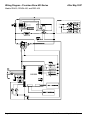
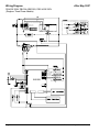
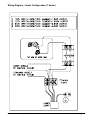
1
Shuttle® Brewer & Airpot/Shuttle® Brewers Operation and Instruction Manual For Models PB-330, PB-430, PBVSA-330, PBVSA-430, PBIC-330, PBIC-430, PB330E 230V, PB-430E 230V, PBVSA-330E 230V, PBVSA-430E 230V, PBIC-330E 230V, PBIC-430E 230V Table of Contents Warning Labels . . . . . . . . . . . . . . . . . . . . . . . . . . 3 Installation and Start-up . . . . . . . . . . . . . . . . . . . 4 Operation . . . . . . . . . . . . . . . . . . . . . . . . . . . . . . 6 Adjustments . . . . . . . . . . . . . . . . . . . . . . . . . . . . 7 Programming . . . . . . . . . . . . . . . . . . . . . . . . . . . 9 Cleaning . . . . . . . . . . . . . . . . . . . . . . . . . . . . . . 13 Service . . . . . . . . . . . . . . . . . . . . . . . . . . . . . . 14 Precision Brew® Control Board . . . . . . . . . . . .15 Troubleshooting Error Messages . . . . . . . . . . . . . . . . . . . . . 17 Models PB-330/PB-330E 230V Models PBIC-430/ PBIC-430E230V Filling Problems . . . . . . . . . . . . . . . . . . . . . 17 Heating Problems . . . . . . . . . . . . . . . . . . . . 19 Brewing Problems . . . . . . . . . . . . . . . . . . . . 21 Parts List . . . . . . . . . . . . . . . . . . . . . . . . . . . . . 24 Parts Photos . . . . . . . . . . . . . . . . . . . . . . . . . . . 25 VS-1.5(S) Cleaning and Sanitizing . . . . . . . . . .29 Wiring Diagrams . . . . . . . . . . . . . . . . . . . . . . . . 30 Prior authorization must be obtained from Grindmaster Corporation for all warranty claims. Models PBVSA-430/ PBVSA-430E 230V Grindmaster Corporation 4003 Collins Lane Louisville, KY 40245 USA (502) 425-4776 (800) 695-4500 (USA & Canada only) (800) 568-5715 (Technical Service Only) FAX (502) 425-4664 www.grindmaster.com © Grindmaster Corporation, 2004 PRINTED IN U.S.A. 0607 Form # AM-344-04 Part # A090-840 Warning Labels The following warning labels were on your dispenser when it was shipped from the factory. They should remain on your dispenser in good, readable condition at all times. If one of your labels is missing or damaged, order a replacement label immediately. Part # A546-445 Located on front splash panel and lid of machine. Located on PB-330, PB-330E 230V, PB-430, and PB-430E 230V lower front decal. Order part # A546-434 for PB-330. Order part # A546-435 for PB-430. Located on PBIC-330, PBIC-330E 230V, PBIC-430, and PBIC-430E 230V above faucet. Order part # A546-428 for PBIC-330. Order part # A546-427 for PBIC-430. Part # A546-213 Located on front splash panel. Part # A71949 Located on brew baskets. CAUTION Hot liquid in brew basket could cause burns. Remove with care. Shuttle Brewers & Airpot/Shuttle Brewers Page 3 Installation WARNING ELECTRIC SHOCK HAZARD! Installation of this appliance should be performed by qualified service personnel only. Improper installation could result in electrocution. Set-Up/Position 1) Remove the brewer from the packing material and attach its legs. 2) Position the brewer on a strong, stable table or counter. Check the level front to back and side to side. Adjust the legs to the correct level. IMPORTANT: THE PERSON INSTALLING THIS APPLIANCE IS RESPONSIBLE FOR ENSURING THAT ELECTRIC AND WATER CONNECTIONS MEET THE REQUIREMENTS OF THE NATIONAL ELECTRIC CODE, NATIONAL PLUMBING CODE, AND ANY LOCAL ORDINANCES. The electric and water hook-up locations are behind the front panel. Remove the four screws fastening this panel for access to these connections. Water Hook-up 1) The water line may enter through holes on the rear or the bottom of the brewer. Use the right hand opening for water. 2) Use 3/8” copper or flexible water line to prevent strain. Do not use low temperature plastic tubing. The connection to the fill valve is 3/8” flare. 3) Water line pressure must be from 30 to 80 psi (207-2 KPA). 4) Hot (up to 160°F/71°C) or cold water may be used. Hot water offers faster recovery between brews. 5) Install a shut-off valve near the brewer. 6) Installing a filtering system can improve the taste of brewed coffee and extend the life of the brewer. If your water has high calcium (lime), chlorine, or iron content, this is especially important. The filter should be the lime inhibiting type if cold water is used. Page 4 Shuttle Brewers & Airpot/Shuttle Brewers Installation (cont.) Electric Hook-up The brewer is designed to operate at the specified voltage on the nameplate with a tolerance of ± 10% for voltage deviation. It is very important that the power line to the brewer be checked to make sure that the voltage is within 10% of the brewer’s rated voltage. Failure to provide adequate voltage, as defined above, will cause problems with your brewer. If the power is too low, the solenoid valves may or may not work or longer recovery time will be experienced. The brewer may be permanently damaged if the voltage is too high. 1) The electric ratings for your brewer are printed on its nameplate. 2) The brewer should be connected to its own circuit with a fused disconnect switch or a circuit breaker near the brewer. Important: For CE units, means shall be provided to endure all pole disconnection from the supply. Such means shall be one of the following: a supply cord fitted with plug, or a switch that is directly connected to the supply terminals and has a contact separation of at least 3mm in each pole. 3) Attach the appropriately sized cord to the brewer with a cord grip for the 1 1/2” (3.8 cm) electric input opening. The cord may enter through the rear or bottom on the left side of the brewer. Use an oil resistant cord such as type SO, SOO, SAO, STOO, SEO, SJO, SJOO, SJTO, SJTOO, SJEO, HSO, HSOO, HSJO, or HSJOO. Alternatively, flexible conduit and type THHN wires may be used. Use only copper conductors. 4) Standard connection is 1 phase 3 wire. Connect the two lines to L1 and L2 on the terminal block. If the brewer is wired for three phase, a lug, L3, is provided on the terminal block. A neutral line must be connected to the N terminal. Note: PB-xxxE 230V models are 1 phase, 2 wire or 3 phase, 3 wire and do not require a neutral. 5) The body of the brewer must be grounded. A ground lug is provided for this purpose. Note: If supply cord is damaged, it must be replaced by a special cord or assembly from the manufacturer, ot it’s service agent. Note: This appliance is IP10 rated, and shall not be cleaned with a water jet. WARNING Never use the ground conductor as a neutral. This could cause electrocution. Start-up 1) Flip power supply to machine “ON” at the branch supply disconnect and allow the water tank to fill. The machine will make a subtle hissing sound while filling. Attention: A watchdog circuit also monitors the water level in the tank and will disable the machine if the water level in the tank is not normal within (6) minutes of fill time. The machine will require power to be reset to clear the watchdog timeout and “ER-1” message will appear. 2) Once the brewer is full, it will take 15 to 35 minutes to heat. The ready lights will turn on when up to temperature. 3) Insert the brew baskets and place a Shuttle or airpot under the baskets. Brew at least one batch from each side. Check the level in the container to be sure the brew volume is correct. Remember that when using coffee, the level will be lower. Do this for all batch sizes. The water must be hot to check the levels. If adjustments are needed, see the adjustments section of this manual. Shuttle Brewers & Airpot/Shuttle Brewers Page 5 Operation CAUTION HOT LIQUID HAZARD! Water used for brewing coffee is very hot. Use caution when brewing, pouring, or transporting coffee. Accidental spills may result in severe burns. 1) Place an empty, warm Shuttle on the shelf, under the brew head. Turn on the warmer if available. 2) If the Shuttle is not warm, allow the warmer to heat the Shuttle. Only a short brew of water will speed this. A cold Shuttle will significantly lower the temperature of the brewed coffee. 3) Remove the filter basket and line with a filter paper. Paper size is 13 x 5 for the smaller basket, BB1.5, and 14 x 6 for the larger, BB2.0. 4) Place ground coffee in the filter basket. Follow corporate recommendations for amount of coffee and grind. A full Shuttle is 1.5 gallons (5.7L). A full vacuum Shuttle is 1.6 (6.0L) gallons. 5) Slide the basket into the brewer making sure the spout lines up with the top of the Shuttle. 6) If ready lights are lit, press correct batch size button. 7) Brew spray time is about 4 minutes for a full Shuttle. After the brew, allow the coffee to drip for 1 to 2 minutes. Ready light will flash during the entire brew spray and drip cycle. Brew basket will be locked in place until drip cycle is finished. CAUTION Coffee basket contains very hot water until the drip is completed. Early removal of a dripping basket could result in burns. 8) Dump the grounds from the basket and rinse for the next brew. Coffee is ready to serve. 9) The Shuttle may be placed on remote warming stations. Use caution when moving a full Shuttle. Page 6 Shuttle Brewers & Airpot/Shuttle Brewers Adjustments All adjustments to machine are accessible through the front display(s). Refer to specifics below and the Programming Routine section. All values are preset at the factory and may vary brewer to brewer. Temperature Adjustment Tank temperature can be adjusted from 170°F – 205°F (77°C – 96°C) through the front display. See Programming Routine section for procedure. Brew Volume “br” Brew time can be set for each size visually. See Setting Brew Volume Procedure below. Brew time can also be adjusted through the display. See Programming Routine section. Setting Brew Volume Visually 1. Remove brew basket and place container under brew head. 2. Press and hold desired brew button for 5 seconds. Display will read “Pro”. 3. Within 20 seconds, press and release desired brew button. Water will dispense from spray head and time will count-up in display. 4. When volume is at desired amount, press and release brew button to stop flow. Time will flash in display. 5. Within 20 seconds, press and release desired brew button. Display will clear and brew time will be stored into memory. Note: During this routine, no pulsing or bypass will occur. Note: If the On/Off button is pressed during procedure, time setting will default to previous time. Pulse Brewing “P-b” Within the Programming Routine, the number of pulses, pulse-on-time, and pulse-off-time for each size brew cycle can be set. During the pulse-off cycle, water shuts off to the coffee grounds. During this period, the grounds in the brew basket absorb water causing the coffee bed to rise. With a larger bed of coffee in the brew basket, remaining water from spray head has more contact area with grounds causing greater extraction of finished coffee. Note: Adjusting pulse values will not affect the finished brew volume. The brew time, however, will be automatically extended by the amount of total pulse OFF time. See Brew Routine Section for examples. Ratio “rto” The ratio of the bypass flow rate versus the spray head flow rate is factory set. This number, however, rarely needs to be adjusted. To find the proper value for the ratio: 1. Within the Programming Routine, set the bypass % to the maximum number allowable. 2. Remove the brew basket. 3. Prepare two containers to measure volume from both the spray head and bypass. 4. Press “Large” brew button to begin dispensing water. 5. After a minute or two, cancel the brew cycle by pressing the “Large” brew button or pressing the On/Off button. 6. Measure the volume of both containers. 7. Divide the bypass amount by the spray head amount. This number is to be entered as the new ratio (ex. “.45”). 8. Access the settings routine and adjust to the new ratio number. Note: If the ratio number is accurate, changing the bypass percent will not require resetting brew time. Note: Approximate ratio numbers: .45 for standard spray head models .64 for gourmet spray head models Shuttle Brewers & Airpot/Shuttle Brewers Page 7 Adjustments (cont.) Bypass “b-P” Brewer contains a bypass valve to control the amount of water to bypass coffee grounds and dilute the final brew. Bypass is available on Large and Medium brew cycles. Within the Programming Routine, the percent of the total brew volume to be bypassed can be set. Note: Adjusting bypass percent will not affect the finished brew volume. The brew cycle time, however, will be automatically reduced as bypass percent increases. Brew Routine No Pulse Brewing or Bypass Assumptions: “br” = 4.00, “P-b” = OFF, “b-P” = OFF 11. Press “Brew” button. 12. 0:00, Brew Valve opens and Ready Light flashes. 13. 4:00, Brew Valve closes. 14. 5:30, Ready Light stops flashing Pulse Brewing ON, Bypass OFF Assumptions: “br” = 4.00; “P-b” = 3, 20, 15; “b-P” = OFF 11. Press “Brew” button. 12. 0:00, Brew Valve opens and Ready Light flashes. 13. 0:20, Brew Valve closes. (Pulse #1) 14. 0:35, Brew Valve opens. 15. 0:55, Brew Valve closes. (Pulse #2) 16. 1:10, Brew Valve opens. 17. 1:30, Brew Valve closes. (Pulse #3) 18. 1:45, Brew Valve opens. 19. 4:45, Brew Valve closes. 10. 6:15, Ready Light stops flashing. Pulse Brewing OFF, Bypass ON Assumptions: “br” = 4.00; “P-b” = OFF; “rto” = 0.45; “b-P” = 20 (max 31) (Software calculates: Brew valve-on-time = 192 sec and Bypass Valve-on-time = 107 sec) 11. Press “Brew” button. 12. 0:00, Brew Valve opens and Ready Light flashes. 13. 1:25, Bypass Valve opens. 14. 3:12, both valves close. 15. 4:42, Ready Light stops flashing. Pulse Brewing and Bypass ON Assumptions: “br” = 4.00; “P-b” = 3, 28, 18; “rto” = 0.45; “b-P” = 30 (max 31) (Software calculates: Brew valve-on-time = 168 sec and Bypass Valve-on-time = 160 sec) 1 1 1 1 1 1 1 1 Page 8 1. Press “Brew” button. 2. 0:00, Brew Valve opens and Ready Light flashes. 3. 0:08, Bypass valve opens 4. 0:28, Both valves closes. (Pulse #1) 5. 0:46, Both valves opens. 6. 1:14, Both valves closes. (Pulse #2) 7. 1:32, Both valves opens. 8. 2:00, Both valves close. (Pulse #3) 9. 2:18, Both valves open. 10. 3:42, Both valves close. 11. 5:06, Ready light stops flashing. Shuttle Brewers & Airpot/Shuttle Brewers Programming (All values are preset at the factory and may vary brewer to brewer.) Settings Routine Programming For All Brewer Settings and Large Portion (refer to Table 1) 11. Press and hold both “up” and “down” arrows for 5 seconds. 12. All three “brew” lights will flash. 13. Press “Large Brew” button. Only “Large” ready light illuminates during remaining steps. 14. Display will indicate either “d F” or “d C” (Fahrenheit or Celsius). Default is “d F”. 15. Press “up” or “down” arrow to change from one to another. 16. Press “Large Brew” button to accept and go to next setting. 17. Display will read temp value in the selected scale (170°F-205°F). Default is “200”. 18. Press “up” or “down” arrow to change value. (1° increments) 19. Press “Large Brew” button to accept and go to next setting. 10. Display will read “Br”. (Brew Time) 11. Press “Large Brew” button to go to next setting. 12. Display will read set brew time in minutes and seconds (0.01-6.00). Default is “4.00”. 13. Press “up” or “down” arrow to change value (1 second increments). (Approximately 0.8 oz./second.) 14. Press “Large Brew” button to accept and go to next setting. 15. Display will read “P-b”. (Pulse Brewing) 16. Press “Large Brew” button to accept and go to next setting. 17. Display will read “OFF” or “1” – “6” (number of pulses). Default is “1”. 18. Press “up” or “down” arrow to change value. (increments of 1) 19. Press “Large Brew” button to accept and go to next setting. Note: If “OFF” is selected, skip pulse timing steps to #26. 20. Display will read “0.05” – “0.60” (pulse ON time for each pulse). Default is “0.40”. 21. Press “up” or “down” arrow to change value. (increments of one second) 22. Press “Large Brew” button to accept and go to next setting. 23. Display will read “0.05” – “0.60” (pulse OFF time for each pulse). Default is “0.40”. 24. Press “up” or “down” arrow to change value. (increments of one second) 25. Press “Large Brew” button to accept and go to next setting. 26. Display will read “rto” (bypass flow rate/spray head flow rate). 27. Press “Large Brew” button to go to next setting. 28. Display will read “0.20 – “1.25” (bypass rate/spray rate). Value is set at factory. If standard spray head, use “0.45, if gourmet or sealed use “0.64”. 29. Press “up” or “down” arrow to change value. (increments of 0.01) 30. Press “Large Brew” button to accept and go to next setting. 31. Display will read “b-P” (percent of brew volume to be bypassed). 32. Press “Large Brew” button to go to next setting. 33. Display will read “OFF” or “1” – “33” (bypass %). Default is 25. 34. Press “up” or “down” arrow to change value. (increments of one percent) 35. Press “Large Brew” button to accept and go to next setting. 36. Display will read “Ltn” (Low-Temp/No Brew). 37. Press “Large Brew” button to go to next setting. 38. Display will read “On” or “Off”. Default is “Off”. 39. Press “up” or “down” arrow to change value. 40. Press “Large Brew” button to accept and clear display. Shuttle Brewers & Airpot/Shuttle Brewers Page 9 Programming For All Brewer Settings and Large Portion (cont.) Table 1 1. PRESS-AND-HOLD UP & DOWN ARROWS FOR 5 SECONDS. 2. READY LIGHTS WILL FLASH. 3. PRESS BREW BUTTON FOR LARGE "L". 4. LARGE READY LIGHT FLASHES THROUGHOUT ROUTINE. 5. DISPLAY WILL READ AS FOLLOWS: DISPLAY READING TEMP SCALE ADJUST ADVANCE OR TANK TEMP (170-205F) OR BREW TIME BREW TIME (0:01-6:00) 4 minutes, 10 seconds shown PULSE BREW # OF PULSES (OFF, 1 - 6) TO PULSE ON TIME (0:05-0:60) # of seconds shown PULSE OFF TIME (0:05-0:60) # of seconds shown BYPASS RATIO BYPASS RATIO (0.20-1.25) 0.45 for Standard Spray Head, 0.64 for Gourmet Spray Head BYPASS BYPASS % (OFF, 1-33) (MAX CHANGE DEPENDING ON RATIO) LOW-TEMP/NO-BREW LOW-TEMP/ NO-BREW Page 10 OR Shuttle Brewers & Airpot/Shuttle Brewers Programming (cont.) Settings Routine Programming For Medium: Brew Time, Pulse Brewing & Bypass (refer to Table 2) 11. Press and hold both “up” and “down” arrows for 5 seconds. 12. All three brew lights will flash. 13. Press “Medium Brew” button. Only “Medium” ready light illuminates during remaining steps. 14. Display will read “Br” (Brew Time). 15. Press “Medium Brew” button to go to next setting. 16. Display will read set brew time in minutes and seconds (0.01-6.00). Default is “2.40”. 17. Press “up” or “down” arrow to change value. (1 second increments) 18. Press “Medium Brew” button to accept and go to next setting. 19. Display will read “P-b” (Pulse Brewing). 10. Press “Medium Brew” button to accept and go to next setting. 11. Display will read “Off” or “1” – “6” (number of pulses). Default is 2. 12. Press “up” or “down” arrow to change value (1 second increments). (Approximately 0.8 oz./second.) 13. Press “Medium Brew” button to accept and go to next setting. Note: If “Off” is selected, skip pulse timing steps. 14. Display will read “0.05” – “0.60” (pulse ON time for each pulse). Default is “0.30”. 15. Press “up” or “down” arrow to change value. (increments of 1 second) 16. Press “Medium Brew” button to accept and go to next setting. 17. Display will read “0.05” – “0.60” (pulse OFF time for each pulse). Default is “0.30”. 18. Press “up” or “down” arrow to change value. (increments of 1 second) 19. Press “Medium Brew” button to accept and go to next setting. 20. Display will read “b-P” (percent of brew volume to be bypassed). 21. Press “Medium Brew” button to go to next setting. 22. Display will read “Off” or “1” – “33” (bypass %). Default is “OFF”. 23. Press “up” or “down” arrow to change value. (increments of 1 percent) 24. Press “Medium Brew” button to accept and clear display. Table 2 1. PRESS-AND-HOLD UP & DOWN ARROWS FOR 5 SECONDS. 2. READY LIGHTS WILL FLASH. 3. PRESS BREW BUTTON FOR MEDIUM "M". 4. MEDIUM READY LIGHT FLASHES THROUGHOUT ROUTINE. 5. DISPLAY WILL READ AS FOLLOWS: DISPLAY READING ADJUST ADVANCE BREW TIME BREW TIME (0:01-6:00) 2 minutes, 40 seconds shown PULSE BREW # OF PULSES (OFF, 1 - 6) TO PULSE ON TIME (0:05-0:60) # of seconds shown PULSE OFF TIME (0:05-0:60) # of seconds shown BYPASS BYPASS % (OFF, 1-33) (MAX MAY CHANGE DEPENDING ON RATIO) Shuttle Brewers & Airpot/Shuttle Brewers Page 11 Programming (cont.) Settings Routine Programming For Small: Brew Time & Pulse Brewing (refer to Table 3) 11. Press and hold both “up” and “down” arrows for 5 seconds. 12. All three “brew” lights will flash. 13. Press “Small Brew” button. Only “Small” ready light illuminates during remaining steps. 14. Display will read “Br” (Brew Time). 15. Press “Small Brew” button to go to next setting. 16. Display will read set brew time in minutes and seconds (0.01-6.00). Default is “1.20”. 17. Press “up” or “down” arrow to change value (1 second increments). (Approximately 0.8 oz./second.) 18. Press “Small Brew” button to accept and go to next setting. 19. Display will read “P-b” (Pulse Brewing). 10. Press “Small Brew” button to accept and go to next setting. 11. Display will read “Off” or “1” – “6” (number of pulses). Default is 4. 12. Press “up” or “down” arrow to change value. (increments of 1) 13. Press “Small Brew” button to accept and go to next setting. Note: If “Off” is selected, skip pulse timing steps. 14. Display will read “0.05” – “0.60” (pulse ON time for each pulse). Default is “0.20”. 15. Press “up” or “down” arrow to change value. (increments of 1 second) 16. Press “Small Brew” button to accept and go to next setting. 17. Display will read “0.05” – “0.60” (pulse OFF time for each pulse). Default is “0.20”. 18. Press “up” or “down” arrow to change value. (increments of 1 second) 19. Press “Small Brew” button to accept and clear display. * During programming routine, all other brew buttons are disabled.r brew buttons are disabled. * If ON/OFF button is pressed during programming routine, brew defaults to previous settings. Table 3 1. PRESS-AND-HOLD UP & DOWN ARROWS FOR 5 SECONDS. 2. READY LIGHTS WILL FLASH. 3. PRESS BREW BUTTON FOR SMALL "S". 4. SMALL READY LIGHT FLASHES THROUGHOUT ROUTINE. 5. DISPLAY WILL READ AS FOLLOWS: DISPLAY READING ADJUST ADVANCE BREW TIME BREW TIME (0:01-6:00) 1 minute, 20 seconds shown PULSE BREW # OF PULSES (OFF, 1 - 6) TO PULSE ON TIME (0:05-0:60) # of seconds shown PULSE OFF TIME (0:05-0:60) # of seconds shown Page 12 Shuttle Brewers & Airpot/Shuttle Brewers Cleaning WARNING Burn Hazard! Hot liquids and surfaces are present in this equipment. To avoid burns use caution when cleaning. Rinse hot parts with cold water before cleaning. Use gloves or a heavy cloth when removing hot parts from brewer. After Each Brew: 1) Dispose of grounds and rinse brew basket. 2) Rinse Shuttle or airpot containers before reuse. Every Day: 1) Wash brew basket with warm soapy water. The wire basket is removable to aid cleaning. 2) Remove spray head(s), located above brew basket(s), using gloves or a heavy towel. Wash off coffee oils and clean any plugged holes. 3) Clean Shuttles with warm soapy water and a brush or towel. 4) Use only a soft cloth and warm soapy water or stainless steel polish on the outside to avoid scratches. 5) Wipe exterior of brewer with a damp cloth. Do not use abrasives which will scratch surface. 6) If Shuttles are to be left on warmer all night, fill with water to avoid coffee oil burn-in. Weekly or Bi-Weekly, Depending on Use 11) Fill Shuttles with one gallon, 2/3 full, of hot water. 12) Pour into the Shuttle liners the recommended concentration of urn cleaner (excessive amounts of cleaner will attack the stainless steel). Urn cleaners that have been used successfully: DIP-IT manufactured by Reckitt Benckiser, Inc. 1655 Valley Road Wayne, NJ 07474 (800) 228-4722 or (973) 633-3600 TABZ™ Super Concentrate manufactured by Urnex Brands, Inc. 170 Ludlow Street Yonkers, NY 10705 (800) 222-2826 or (914) 963-2042 13) Scrub the liner interior with a plastic bristle brush. 14) Remove the knurled nut at the top of the gauge glass and clean the glass with a small bottle brush. 15) Pour out the contents of the Shuttle. 16) Remove the handle assembly of the Shuttle faucet by unscrewing the plastic bonnet. 17) Gently wash the faucet seat cup with a soft cloth and warm soapy water. 18) Wash the faucet shank with a bottle brush. 19) Soak airpot pick-up tube assembly in hot soapy water. Urn cleaner may be used for stronger cleaning.1 10) Clean the warmer and bottom of Shuttle surfaces. These surfaces must be clean for proper heat transfer. 11) Polish the exterior of the brewer with stainless steel cleaner. Use the appropriate cleaner for brass, copper, or vinyl if these optional finishes are provided. Shuttle Brewers & Airpot/Shuttle Brewers Page 13 Service The rest of this manual contains information to aid the service person who is working on this equipment. This page has information on performing common service tasks. Following this is the Troubleshooting section which can help diagnose problems which are divided into three basic systems: filling, heating, and brewing. Next is an illustrated parts breakdown which will help in the selection of repair parts. If further assistance is needed, call our Technical Service Department at 800-695-4500 (USA & Canada only) or (502) 425-4776 Monday – Friday between 8:00 am and 6:00 pm Eastern time. Wiring diagrams are also provided. Locate the basic diagram for the model you are working with. If there are any options, see Diagram #091-548 (page 31 of this manual) which shows the wiring alterations for options. Drain Water Tank Always empty the tank before shipping. WARNING Draining of tank should be performed by a qualified service technician. The tank contains very hot water. May cause severe burns. Note: Brewer may contain over 5 gallons (19.0L) of hot water. 1) Prepare a heat resistant container to drain tank water into. 2) Disconnect power to the brewer. 3) Remove the front access panel. 4) Pinch or clamp the silicone hose connected to fill valve. 5) Disconnect hose from outlet barb on fill valve. 6) Place hose over drain and release clamp. 7) Allow the tank to drain completely. NOTE: It may be necessary to pinch the hose and stop the water before container is full. Carefully reinstall hose over fill valve outlet, then empty container. Repeat steps 4-7 completely to drain tank. Remove Brew Valve 1) Disconnect power to machine. 2) Remove top cover and remove wires and small tube from valve. 3) Tilt inlet of valve down and pull sideways out of spray tee. 4) Clamp rubber tubing and disconnect valve from tubing. Remove Heater 1) Disconnect power and remove top cover of brewer. 2) Disconnect wire leads to heater. 3) Remove tank cover by loosening retaining screw(s). Cover is lifted up with heater attached. Heater is then removed. 4) Replace heater with sealing washers in same configuration. When tightening nuts, hold element so it does not twist. 5) Replace tank cover ensuring gasket seal is good. 6) Replace heater wires. Be sure all electrical connections are secure. Page 14 Shuttle Brewers & Airpot/Shuttle Brewers Special Control Functions User Lockout User Lockout is achieved via the position of the LOCK jumper on the board header. Locate the header on the board (shown below) and place the jumper in the desired position. In the Locked position all menus in this document are locked out, and the unit will only allow brewing functions. There are two versions of the header, 10 pin and 2 pin. Both configurations are shown below. 10 Pin Version 2 Pin Version UNLOCKED UNLOCKED 1 LOCK LOCKED 1 LOCK LOCK LOCKED LOCK System Restore Function This function will restore a Precision Brew® unit to its original factory settings. To activate system restore, power on the unit while holding in the DOWN button on the keypad (use the keypad that controls the RIGHT side for a double unit). Continue holding the DOWN button and the display will scroll “rEStorE” to indicate that a system restore is about to happen. If the DOWN button is released at this point, the restore is cancelled. If the button hold is continued, the display will scroll “donE” to show completion of a system restore. Upon a successful restore, the original factory settings will override all changes. The brew counters are not affected. Factory Specific Features The following sections describe features that are not intended to be used by the end user. These features, instead, are intended to help Grindmaster set up and test the machine. Factory/Field Test Menu This menu is intended to check product functionality both at the end of the factory line and in the field. The control must be completely OFF (both sides) to enter field test. This mode is entered by pressing and holding the UP key and the LARGE BREW key on the keypad (use the keypad that controls the RIGHT side for a double unit) for 6 seconds. Once the menu is entered, the unit will start with an LED test that lights all LEDs and segments on the display. Proceeding through the field test is done by pressing the ON/OFF key (RIGHT side if a double unit). Each time this button is pressed, the test will advance to the next step. For the output test, use the UP and DOWN keys to select the desired output. Refer to the table on the following page for operation. Field Test Mode exits after stepping through all modes only- there is not a timeout. Shuttle Brewers & Airpot/Shuttle Brewers Page 15 Factory/Field Test Menu (cont.) Step Function Operation Description 1 LED Test All LEDs ON Verify that all LEDs turn on. 2 Firmware Version Display firmware version Shows the software version of the control. 3 Date Code Not used Not used 4 EEPROM Version Not used Not used 5 Non Resetable Unit Counter Scroll non-resetable unit counter Shows the total number of brews made by the brewer (both sides if a double unit) 6 Display Water Temperature Show averaged A/D reading of temperature Shows the current temperature in °F of the thermister. 7 Display Water Level 1 Show averaged A/D reading of water level 1 If > 500 water level is full, If < 500 water level is not full. 8 Display Water Level 2 Show averaged A/D reading of water level 2 If > 500 water is at the heater level, If < 500 water level not at the heater level. 9 Show Input Display scrolls “InPut” 10 Input Test Press each key and the display will show a Right Side number related to that key On/Off - 1 (advances test) Up - 5 Down - 3 Large Brew - 4 Medium Brew - 2 Small Brew - 0 Basket Switch - 17 Left Side On/Off - 9 Up - 13 Down - 11 Large Brew - 12 Medium Brew - 10 Small Brew - 8 Basket Switch - 16 11 Show Output Display scrolls “outPut” Output Test Mode 12 Output Test Turns on each relay separately. Displays “O##“ where: Scroll through relay outputs with the UP and DOWN keys. Input Test Mode ## = 2 digit output number Outputs are as follows: IMPORTANT: Each output will be turned ON when its number is on the display REGARDLESS of temperature or fill level. Be CAREFUL not to overfill the tank and keep electric items out of the way of the brew channel. Page 16 O01 O02 O03 O04 O05 O06 O07 O08 O09 O10 - Fill Valve - Right Bypass Valve - Left Bypass Valve - Right Brew Valve - Left Brew Valve - not used - not used - Right Basket Lock - Left Basket Lock - Tank Heater Shuttle Brewers & Airpot/Shuttle Brewers Troubleshooting The following pages are provided to help determine the cause of problems with operation of the brewers and to indicate the appropriate solution for the problems. For each problem, the possible causes should be checked in the order shown until the exact nature of the problem is determined. The following procedures must be performed by a qualified service technician. Disconnect power to machine before servicing. Error Messages Problem Possible Causes Service Check Remedy ER1 • Fill valve on for over • Check system for 6 min. (This occurs water leaks. during initial fill on some units – see Initial Start-up.) • Correct any leaks and reset controller. ER2 • Thermistor failure or loose connections in thermistor circuit. • Ensure that connector is securely attached to controller and that thermistor is securely connected. • Secure connections and reset controller. If error reoccurs, replace thermistor. ER3 • Thermistor is reading out of range. • Check tank temperature. • Replace thermistor. ER4 • No heat is detected • See Heating Problems • See Heating Problems Filling Problems Problem Possible Causes Service Check Remedy Overfilling water tank when power is Off • Fill valve not sealing properly. • Check to see if water • Disassemble valve and clean enters tank continuously out debris. Valve may need to (usually at a slow rate). be replaced. Overfilling water tank only when power is On • High electrode coated with lime or faulty. • Disconnect electrode • Remove electrode assembly wire at quick connect and clean the probes. If (brown wire). Connect a problem is not corrected, wire from the quick conreplace electrode assembly. nect to the cabinet body. If filling stops, this is the error cause. • Connection from control board to tank body faulty. • Check to ensure connection (red wire) is secure. • Control board is faulty. • Secure connection from • Replace control board. control board to metal enclosure does not stop filling. Shuttle Brewers & Airpot/Shuttle Brewers • Make connection to tank secure. Page 17 Troubleshooting (cont.) Filling Problems Problem Tank does not refill Page 18 Possible Causes Service Check Remedy • No electrical power to equipment • Check for proper • Establish electrical power voltage at terminal to unit. block. Check circuit breaker on supply circuit. • No water supplied to equipment • Disconnect water supply line and ensure that water is provided to unit. Check to see that any and all valves in water line are open. • No power to control board • Check for proper voltage • If there is not 120V across across transformer primary, proceed to step primary terminals by entitled “No power to control disconnecting terminals. board and transformer not See wiring diagram for powered.” If there is proper more information. voltage across primary, proceed to step entitled “No power to control board and transformer powered”. • No power to control board and transformer not powered. • Ensure there is proper voltage across terminal block. Check wiring diagram for more information. • No power to control board and transformer powered. • Disconnect quick • If there is not 24 Vac between disconnect on secondary the blue and yellow wires, side of transformer at replace transformer. If proper quick disconnect voltage exists, secure between yellow and blue connection between 3 pin wires. Check for 24 Vac connector and control board. between blue and yellow wires. • Establish water supply to unit. • Secure connections and reset circuit breaker on equipment. Shuttle Brewers & Airpot/Shuttle Brewers Troubleshooting (cont.) Filling Problems Problem Tank does not refill Possible Causes • Fill valve or control board is faulty Service Check Remedy • Check to ensure proper • If 6 pin connector is securely connection between attached to control board and 6 pin connector and con- all connections are secure trol board. Check and there is 24 Vac across for proper connections fill valve terminals, replace at fill valve terminals. fill valve. Drain 1 gal. (3.8L) of water from hot water faucet. Check for 24 Vac across fill valve terminals. Heating Problems Problem Tank does not heat Possible Causes Service Check Remedy • No electrical power to equipment • Check for proper voltage • Establish electrical power at terminal block. Check to unit. circuit breaker on supply circuit. • No power to control board • Check for proper voltage • If there is not proper voltage across transformer across primary, proceed to step primary terminals by entitled “No power to control disconnecting terminals. board and transformer not See wiring diagram for powered”. If there is proper more information. voltage across primary, proceed to step entitled “No power to control board and transformer powered”. Shuttle Brewers & Airpot/Shuttle Brewers Page 19 Troubleshooting (cont.) Heating Problems Problem Tank does not heat Possible Causes Service Check Remedy • Low (long) electrode coated with lime or faulty. • Disconnect electrode • Remove electrode assembly wire at quick connect and clean the probes. If (purple wire). Connect a problem is not corrected, wire from the quick conreplace electrode assembly. nect to the cabinet body. If heating begins, this is the error cause. • Connection from control board to tank body faulty. • Check to ensure connection (green wire) is secure. • Make connection to tank secure. • Connections from control board to heater relay faulty. • Check to ensure connections (gray and blue wires) are secure. • Make connections to relay secure. • Line voltage connections • Check to ensure • Make connections to connections (black and to heater relay faulty. relay secure. brown wires) are secure. Page 20 • Connections to remainder of heater circuit faulty. • Check to ensure connections from relay to thermal cut-out and from thermal cut-out to contactor and from contactor to proper terminal of terminal block are secure. See wiring diagram for more infomation. • Heater relay faulty. • Ensure that coil on • If the relay coil is energized heater relay is energized and there is an open circuit by ensuring that there is across the connection tabs, 24 VDC between the replace relay. gray and blue wires attached to the relay. Remove the black and brown wires from the relay and check for an open circuit across the connection tabs (COM and NO) to which the wires were attached. • Thermal cut-out tripped or faulty. • Check for open circuit on thermal cut-out. (NOTE: Tripping of thermal cut-out can indicate presence of another problem with the unit. Unit should be monitored) • Make connections secure. • Replace thermal cut-out. Shuttle Brewers & Airpot/Shuttle Brewers Troubleshooting (cont.) Heating Problems Problem Tank does not heat Possible Causes Service Check Remedy • Contactor faulty. • Ensure that coil on • If the contactor coil is contactor is energized energized and there is an by ensuring that there open circuit across any of is proper voltage the contactor poles, replace between the brown and contactor. white wires attached to the relay. Check each side of the contactor (Line and Load) at each pole for continuity. • Heater faulty. • Check resistance across element(s) with power conductors disconnected. • If resistance is much less than 8 Ohms or much more than 15 Ohms, replace heater(s). • Control board is faulty. • Check to ensure proper connection between connector 5-pin and control board. Check for proper connections in all heater control circuitry. Check for proper connections between N terminal of contactor coil and terminal block. • If 5-pin connector is securely attached to control board and all connections are secure and functioning except there is not 120 Vac across contactor coil terminals, replace control board. Brewing Problems Problem Brew volume too large or too small Possible Causes Service Check Remedy • Portion selected on touchpad not correct. • Review timer settings versus portion size. • Adjust timer to desired value or select different portion size. • Timer not set properly. • Compare timer setting to either factory setting or initial user setting to determine if it has been changed. • Adjust timer to desired value. Shuttle Brewers & Airpot/Shuttle Brewers Page 21 Troubleshooting (cont.) Brewing Problems Problem Brew volume too large or too small Brew volume erratic Possible Causes Service Check Remedy • Sprayhead clogged. • Visually check for clogging of holes in brewhead. • Clean all holes. • Brew valves clogged with lime deposits. • Visually inspect brew valve at hose connections. • Clean lime from valve. Seat, cup or entire valve may need replacement. • Water supply pressure or flow rate not adequate. • Check to see that fill valve cycles on and off frequently during brew cycle when all brew heads are used simultaneously. Check to ensure that water supply line is 3/8” and pressure is between 30 and 80 psi (207 and 552 KPA). • Supply water at adequate pressure and flow rate. • Water supply pressure fluctuates. • Check water pressure with and without other appliances operating. • Plumb water supply so that water pressure is not significantly affected by other appliances. Note: Small variations from batch to batch are normal. Brew cycle will not start Page 22 • Optional momentary switch to indicate container in place not engaged or faulty. • Check to see that • If fully engaged switch does container fully engages not complete circuit across switch. Check for terminals of switch, replace continuity across switch switch. when switch is engaged. • Brew circuit connections not secure. • Check to see that connector (6-pin) is securely connected to control board. Check to see that all connections from controller through brew valve are secure. • Brew valve faulty. • If there is 24 Vac across • Check to see if there is 24 Vac across brew valve terminals and brew valve is not open, replace valve. terminals. • Touchpad faulty. • Check to see that touchpad connections to control board are secure. • Secure connections. • If connections are secure, other functions appear normal and touchpad will not initiate a brew cycle, replace touchpad. Shuttle Brewers & Airpot/Shuttle Brewers Troubleshooting (cont.) Brewing Problems Problem Possible Causes Service Check Remedy Brew cycle will not start • Controller faulty. • Check to see that the • If there is not 24 Vac across power is supplied to the brew valve, replace control controller by following board. instructions given in the Troubleshooting section on Filling Problems. Once touchpad and momentary switch integrity is assured (see above), initiate a brew cycle and check for 24 Vac across brew valve. Sprayhead will not stop dripping water • Brew valve not closing completely. • Visually inspect brew valve at hose connections. • Clean lime from valve. Seat, cup or entire valve may need replacement. • Water in tank boiling. • Remove sprayhead and determine if drip is coming from overflow. • Reduce tank temperature. If you still need help, call our Service Department at (800) 695-4500 (USA and Canada only) or (502) 425-4776 (Monday-Friday 8:00 am - 8:00 pm EST) or an authorized service center in your area. Please have the model and serial number ready so that accurate information can be given. Prior authorization must be obtained from Grindmaster Corporation’s Technical Services Department for all warranty claims. Shuttle Brewers & Airpot/Shuttle Brewers Page 23 Parts List for All Precision Brew Models Models PB-330, PB-430, PBVSA-330, PBVSA-430, PBIC-330, PBIC-430 ITEM DESCRIPTION PART # Reference Front View Picture: 1 Controller PB Single 2 Relay, Heater 24vdc 3 Valve, Inlet 24vac 4 Terminal Block 5 Spray Head 6 Orifice Bypass 7 Fitting Assy Water Inlet 8 Switch Momentary ** PBIC only A530-056 (prior to May 2007); A530-059 (after May 2007) A531-072 (prior to May 2007); A71450 (after May 2007) A537-189 A531-035 APT400-010 A518-045 A718-226 A531-025 Reference Lower Warmer Picture: 20 Faucet Hot Water 21 Light Warmer 22 Switch Warmer 23 Heater Warmer 120V 100W 23 Heater Warmer 220V 100W A537-043 A515016 A531-026 A535-018 A535-079 (for E230V models) Reference Top View Picture: 30 Thermostat, Hi Limit 31 Contactor 4-Pole** 31 Contactor 2-Pole ** 31 Contactor for 2-Pole E230V models 31 Contactor for 4-Pole E230V models 32 Transformer, 120/208/240 100W 33 Valve, Brew 24VAC PB 34 Valve, Bypass 24VAC PB 35 Solenoid, Basket Lock 24vdc 36 Touchpad PB Series 37 Board AC-DC Rectifier 38 Spray Elbow 39 Tee Barbed 3/8" 40 Hose Overflow 41 Hose Silicone 42 Elbow Silicone A536-023 A514005 (for models with 3 heaters) A515027 A531-083 E531-076 A554-137 A537-184 A537-183 A554-135 A530-057 (prior to May 2007); A530-060 (after May 2007) A530-058 (prior to May 2007 only) A518-046 A61152 A585-016 A512012 A548-129 Reference Tank Lid Picture: 50 Element Ht 5kW 240V (PB, PBVS) 50 Element Ht 5kW 240V (PBIC) 50 Element Htr 6.6kW 240V ** (PB, PBVSA) 50 Element Htr 6.6kW 240V ** (PBIC) 50 Element Htr 3.7kW 240V ** (PB, PBVSA) 50 Element Htr 3.7kW 240V ** (PBIC) 51 Thermistor 52 Electrode Assembly 53 Gasket Tank ** ** part not shown Page 24 A535-010 A535-072 A535-059 A535-071 A535-068 A535-073 A725-097 A712-018 A544-029 (for models with 3 heaters) (for models with 3 heaters) (for models with 3 heaters) (for models with 3 heaters) Shuttle Brewers & Airpot/Shuttle Brewers Front View (refer to key on page 24) 6 2 2 6 5 5 1 1 7 4 3 7 4 (prior to May 2007) 3 (after May 2007) Lower Warmer (refer to key on page 24) (PB-430 pictured) 23 23 20 21 21 22 Shuttle Brewers & Airpot/Shuttle Brewers 22 Page 25 Top View (refer to key on page 24) 36 38 35 36 35 42 32 34 30 Tank Lid (refer to key on page 24) 3 Heater Model shown 52 51 50 50 Page 26 Shuttle Brewers & Airpot/Shuttle Brewers Shuttle Parts List for PB-330 and PB-430 only 6 5 4 3 2 1 ITEM DESCRIPTION PART # 1 Faucet Model ES A537-053 2 Shank w/ Chrome Bonnet A522078 3 Gauge Assembly A718-018 4 Kit, Shuttle Lid A725-092 S.S. Shuttle Cover (not shown)* A713-027 5 Lid Retaining Clip A548-142 6 Lid Stopper w/ O-Ring A548-140 A61365 * S.S. Cover used until August 2001 A318-119P Top Gage Fitting A537-055 Handle A522026 Washer Upper Gage A555-001 Gage Shield A522132 Bonnet Nut A522120 Spring A522031 Gage Glass A537-047 Plastic Stem A522102 Silicone Seat Cup A522027 Washer Lower Gage AA-958 Gage Base Upper Faucet (Part # A537-049) Shuttle Brewers & Airpot/Shuttle Brewers Gauge Assembly (Part # A718-018) Page 27 ITEM NO. 1 2 3 4 5 6 7 8 9 Page 28 Title Stand Body Tray for Stand Vacuum Shuttle Stand Base Tray Top Self-Tapping Screw .5" Rubber Foot Plastic Insert Self-Tapping Scres .75" 2 5 1 6 9 4 8 PART NUMBER A548-157 A548-159 VS-1.5 A548-158 A517-018 A539-217 A548-161 A548-162 A539-218 3 7 VS-1.5S VS-1.5S/QTY. 1 1 1 1 1 4 4 3 3 4 ITEM NO. 1 2 3 4 5 6 7 8 5 2 Title Stand Body Tray for Stand Stand Base Tray Top Stand, Top Plate NUT M4 W Nylon Insert Self-Tapping Screw .5" Rubber Foot 6 VS-S 1 3 PART NUMBER A548-157 A548-159 A548-158 A517-018 A517-019 A540-237 A539-217 A548-161 7 8 VS-S/QTY. 1 1 1 1 1 4 4 4 Model VS-1.5 Vacuum Shuttle Parts List Shuttle Brewers & Airpot/Shuttle Brewers Cleaning & Sanitizing Instructions for Model VS-1.5(S) These cleaning and sanitizing instructions are only a guideline to be used for the cleaning and sanitizing of the VS-1.5S and VS-S with VS-1.5. In-house cleaning and sanitizing methods may be more effective. Grindmaster assumes no responsibility for the food born illness and/or sickness caused by using improper sanitizing methods. For cleaning and sanitizing of the VS-1.5S and VS-S with VS-1.5 the three-sink method is recommended. The threesink method consists of the sink full of hot soapy water using an approved detergent, a fresh water rinse, and an aqueous sanitizing solution using an approved iodine sanitizer with mixture between 12.5-25 PPM. 1) Rinsing the unit after use: a) Rinse unit with hot water and empty completely. b) Fill unit with hot water. c) Open unit and empty contents completely by opening the faucet completely. 2) Cleaning and sanitizing lid assembly: a) Remove lid from unit, fully submerse it in cleaning solution. Using a clean cloth, wipe the unit thoroughly. b) Using supplied brush, clean mixing tube thoroughly. c) Rinse with clean water. d) Submerse in sanitizing solution for 5 minutes then air dry completely. 3) Cleaning and sanitizing body assembly: a) Remove unit from the base. (only when using VS-S with VS-1.5) b) Completely fill the unit with cleaning solution. Using a clean cloth, wipe the unit thoroughly. c) Rinse unit thoroughly with fresh water. d) Remove faucet, shank, and sight gauge from unit and place in cleaning solution. e) Open lid on the bottom of the unit and remove silicon tube (Tank to Faucet Tube) and place in cleaning solution for cleaning. f) Reassemble unit. g) Fully fill unit with sanitizing solution for 5 minutes and drain through fully opened faucet. h) Wipe outside of the unit with a clean cloth moistened with sanitizing solution. i) Place unit on rack upside down to thoroughly air-dry. 4) Cleaning Stand Assembly and tray: a) Remove tray and tray top and place in cleaning solution. Using a clean cloth, clean tray and tray top thoroughly. b) Wipe outside of the stand with a clean cloth moistened with sanitizing solution. c) Place parts on rack to thoroughly air-dry. 5) Cleaning the Faucet assembly and silicone tube: a) Using supplied brush, clean silicone tube, sight gauge tube, and shank assembly. b) Rinse parts and place in sanitizing solution for 5 minutes, remove and air dry. c) Remove top from faucet and use brush to clean inside, rinse and place in sanitizing solution for 5 minutes. Remove and air dry. 6) When all pieces are completely dry reassemble for use. Shuttle Brewers & Airpot/Shuttle Brewers Page 29 Wiring Diagram - Precision Brew 430 Series Prior to May 2007 Models PB-430, PBVSA-430, and PBIC-430 Page 30 Shuttle Brewers & Airpot/Shuttle Brewers Wiring Diagram - Precision Brew 330 Series Prior to May 2007 Models PB-330, PBVSA-330, and PBIC-330 Shuttle Brewers & Airpot/Shuttle Brewers Page 31 Wiring Diagram Prior to May 2007 PB-430E 230V, PBVSA-430E230V, PBIC-430E 230V (Single or Three Phase Models) Page 32 Shuttle Brewers & Airpot/Shuttle Brewers Wiring Diagram Prior to May 2007 PB-330E 230V, PBVSA-330E 230V, PBIC-330E 230V Brewers Shuttle Brewers & Airpot/Shuttle Brewers Page 33 Wiring Diagram - Precision Brew 430 Series After May 2007 Models PB-430, PBVSA-430, and PBIC-430 Page 34 Shuttle Brewers & Airpot/Shuttle Brewers Wiring Diagram - Precision Brew 330 Series After May 2007 Models PB-330, PBVSA-330, and PBIC-330 Shuttle Brewers & Airpot/Shuttle Brewers Page 35 Wiring Diagram After May 2007 PB-430E 230V, PBVSA-430E230V, PBIC-430E 230V (Single or Three Phase Models) Page 36 Shuttle Brewers & Airpot/Shuttle Brewers Wiring Diagram After May 2007 PB-330E 230V, PBVSA-330E 230V, PBIC-330E 230V Brewers Shuttle Brewers & Airpot/Shuttle Brewers Page 37 Wiring Diagram - Heater Configuration (3 Heater) Page 38 Shuttle Brewers & Airpot/Shuttle Brewers Wiring Diagram - Heater Configuration (1 Heater) Shuttle Brewers & Airpot/Shuttle Brewers Page 39 Grindmaster® Coffee Grinders and Brewers • PrecisionBrew™ Brewing Systems • Espressimo® Espresso Machines Crathco® Hot Beverage Dispensers • Crathco® Cold and Frozen Beverage Dispensers • AMW Coffee and Tea Systems Tel (502) 425-4776 • Fax (502) 425-4664 • 1-800-695-4500 (USA & Canada only) P.O. Box 35020 • Louisville, KY 40232 • USA © Grindmaster Corporation, 2003 0607 Form # AM-344-04 www.grindmaster.com • email: [email protected] PRINTED IN USA Part # A090-840