1
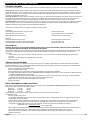
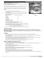
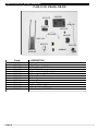
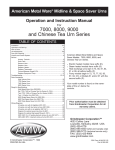
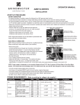
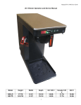
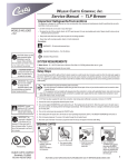
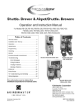
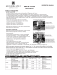
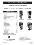
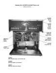
OPERATIONS MANUAL
ICB-400, ICB-300, P-430,
P-330, RAP-430, RAP-330,
RAPS-430, RAPS-330
INSTALLATION
WARNING: ELECTRIC SHOCK HAZARD! Installation of this appliance should be performed by qualified service
personnel only. Improper installation could result in electrocution.
SET-UP AND POSITIONING OF BREWER
• Remove the brewer from packaging material and attach legs.
• Position the brewer on a strong, stable table or counter. Check the level front to back and side to side. Adjust legs as necessary to level
the unit.
WATER AND ELECTRICAL CONNECTIONS
IMPORTANT:THE PERSON INSTALLING THIS APPLIANCE IS RESPONSIBLE FOR ENSURING THAT ELECTRIC AND WATER
CONNECTIONS MEET THE REQUIREMENTS OF THE NATIONAL ELECTRICAL CODE, NATIONAL PLUMBING CODE AND ANY LOCAL
ORDINANCES.
The water and electrical connection locations are behind the front panel on the right side of the brewer. Remove the screws fastening this panel
to the unit to access these connections.
WATER HOOK-UP
• The water line may enter the brewer through holes in the bottom or rear of the brewer.
• Use 3/8” copper tubing or flexible water line to prevent strain. Do not use low temperature plastic tubing. The connection to the fill valve
is 3/8” flare.
• Water line pressure should be between 30 and 70 psi.
• Hot (up to 160°F) or cold water may be supplied to the unit. Hotter water will allow faster recovery between brews.
ELECTRICAL POWER SUPPLY HOOK-UP
• The electric ratings for this brewer are printed on the nameplate attached to the unit. Always see the name plate for rating information for
the particular brewer.
• The brewer should be connected to its own dedicated circuit with a fused disconnect switch or circuit breaker near the brewer.
• Attach the appropriately sized cord to the brewer with a cord grip for the 1-1/8” electric input opening in either the rear or bottom of the
unit. Use an oil resistant cord such as type SO, SOO, SAO, STOO, SEO, SJO, SJOO, SJTO, SJTOO, SJEO, HSO, HSOO, HSJO or
HSJOO. Alternatively, flexible conduit and type THHN wires may be used. Use only copper conductors.
• Standard units are single element units and are wired internally for single phase, 3 wire service. Connect the neutral line to the N terminal
of the terminal block and the 2 conductors to L1 and L2 of the terminal block. 3 element units may be connected to single or 3-phase
service. 3 element, single-phase units should be connected as described above. For 3 element units intended to operate with a 3 phase
power supply, connect the third phase conductor to L3 of the terminal block.
• The body of the brewer must be grounded. Connect the ground conductor to the ground lug located near the terminal block.
WARNING: ELECTRIC SHOCK HAZARD! Never use the ground conductor as a neutral. This could cause
electrocution.
INITIAL START-UP
• Turn on the water supply to the brewer. Check for leaks at the supply line to fill valve connection. Remove the controller cover panel.
• Turn on the electrical power. The brewer will begin to fill. Units that require more than 5 min. to fill will display an error message “ER1” on
the controller after 5 min. of filling. Press the SELECT button on the controller for 10 sec. to reset the unit and continue filling. To reset the
controller, the SELECT button must be pressed while the LED’s indicate ER1. If the SELECT button is momentarily pressed a timer
numerical value will be displayed. If this occurs, wait 10 sec. and the error message will again be displayed; press the SELECT button for
10 sec. to reset controller and resume filling.
• After the tank has filled, replace the controller cover panel.
• Turn on power and the water heating cycle will begin; it will take 15-35 min. to complete the heating cycle. The WATER HOT light on the
front of the unit will turn on when the water has reached temperature.
• The brewer can now be operated to evaluate brew timer settings and then make adjustments as necessary.
The brewer timers settings are preset at the factory to the following values:
Small brew
(0.75 gal.)
120 sec.
Medium brew (1.25 gal.)
165 sec.
Large brew
(1.75 gal.)
230 sec.
• Insert the brew baskets and place the appropriate container under the brew basket.
• Portion size is selected with the touchpad located on the front of the brewer. The upper right hand area of the touchpad has 2 LEDs. If
both are lit the unit is set to brew the large volume. If only the upper LED is lit, the brewer will brew the medium volume; if only the lower
LED is lit, the brewer will brew the small brew volume.
AMERICAN METAL WARE® BREWERS
INITIAL START-UP (cont’d)
Once the appropriate selection is made, press the START switch on the touchpad to begin dispensing water through the sprayhead. Brew at least
1 batch for each timer setting. Check the level in the container to be sure the brew volume is correct. Remember that when using coffee, the level
will be lower than it will be when using water only. This should be done for each side on dual brewer models.
• Using a thermometer, measure the temperature of the water draining from the brew basket during the initial timer checkout.
• If the timer settings or temperature need adjustment, see the Adjustment Section of this manual on pages 4-5.
USER CONTROLS
ROUTINE OPERATION CONTROLS
TOUCHPADS
Single brewer models incorporate 1 touchpad while dual brew models utilize 2 touchpads. On ICB units, the top touchpad controls the left side
brewer and the lower touchpad controls the right side brewer (see Figure A). On the P-430 Series, the left touchpad controls the left brewer and
the touchpad located on the right controls the right side brewer (see Figure B).
These touchpads are used to select PORTION SIZE and to START the brewing cycle. Red LEDs are used to indicate the selected settings. An
illustration of the touchpads is shown below.
Portion size LEDs
Start/Portion size
selector switch
Portion size LEDs
Start/Portion size selector switches
Figure A
Figure B
STOP SWITCH
Red STOP switches are located adjacent to the touchpads. These rocker switches cancel ongoing brew cycles. Operating these switches will
close the brew valve and reset the controller to a waiting to brew status. To stop a brew, momentarily press the switch to its alternate position and
release. TO PREVENT RISK OF BURNS OR INJURY, DO NOT REMOVE THE BREW BASKET UNTIL ALL COFFEE HAS DRAINED FROM
THE BREW BASKET.
INTERRUPT SWITCH
A detent switch is located on the cabinet of each ICB series brewer and must be engaged by proper positioning of the container; this switch
serves to ensure that a brew cycle will not begin unless a container is in place under the brewbasket or that a cycle will be suspended in the
event that a container is removed from it’s proper position.
If a brew has been started and the container is removed, the brew valve will close.
Note: The brew basket will continue to drain when the container is removed. The timer will continue to elapse time. In the event that a container
is again placed in the proper position, brewing will continue for the period of time remaining in the cycle.
Page 2
AMERICAN METAL WARE® BREWERS
TEMPERATURE AND BREW TIMING CONTROLS (Refer to Figure C)
Temperature and brew timing are set by the dial and keypad located on the main controller.
This controller is positioned inside the brewer housing and is accessed by removing the
screws which fasten the access panel to the brewer.
Alphanumeric LEDs to indicate
timer settings and to display
error codes
Red LEDs to indicate
which timer is being
programmed
The controller stores 6 independent brew timer values. On dual brewer models, 3 timers
are used for the left brewer, and 3 are used for the right brewer. On single brewer models,
the timers for the left side brewer are utilized for the unit and the right brewer timers are
not utilized.
BREWER SELECTOR SWITCH
Pushbuttons to adjust timer
values and to select timers
The brewer selector switch is a 2-position slide switch located on the main controller. On
dual brewer models it is used to select the left or right side timers for programming. On
single brewer models, the switch should always be in the left position when programming
the brew timers. To switch from side to side, slide switch to the desired position.
PUSHBUTTON KEYPAD
Water temperature adjustment
Brewer selector switch
Figure C
The pushbuttons serve 4 functions:
1) Selecting the appropriate timer
2) Adjusting the stored timing value
3) Instructing the controller to store a displayed value
4) Resetting the controller after an error has been registered
The pushbutton to the right on the controller is used for 1, 3 and 4. The pushbutton to the left on the controller is used to increase the displayed
value. The middle pushbutton is used to decrease the displayed value.
To select the appropriate timer once the correct brew side has been selected, press the SELECT pushbutton until the correct brew size LED is lit.
To adjust the stored timing value, press the left pushbutton to increase the displayed value or press the middle pushbutton to decrease the displayed
value.
To store a displayed value, press the select button once.
To reset the controller after an error has been registered, press the right pushbutton and hold for 10 sec. After resetting, the alphanumerical LEDs
will return to displaying timer values.
TEMPERATURE ADJUSTMENT KNOB
Temperature adjustment is accomplished by rotating the small knob to the left of the brewer selector switch. Clockwise rotation will increase the
o
temperature setpoint while counterclockwise rotation will decrease the setpoint. The standard factory setting is 195 F.
OPERATION
WARNING: WATER USED FOR BREWING COFFEE IS VERY HOT. USE CAUTION WHEN BREWING, POURING OR TRANSPORTING
COFFEE. NEVER ATTEMPT TO MOVE THE BREWER WITHOUT FIRST DRAINING THE WATER TANK. ACCIDENTAL SPILLS MAY RESULT
IN SEVERE BURNS.
ICB brewers will perform the brew function only when a container is properly located under the brew basket; the pushbutton switch must be
engaged to allow brewing. Removal of the container during a brew cycle will suspend the brewing cycle, however brew timing will continue to
elapse and the brew basket will continue to drip.
• Place an empty shuttle, airpot or insulated container on the shelf, counter, or accessory base (depending on model) under the brew basket.
A cold container will significantly lower the temperature of the brewed coffee. Turn on the warmer if a shuttle is used. If the shuttle is not
warm, allow the warmer to heat the shuttle. A short brew of water will quickly warm the container.
• Remove the filter basket and line with a filter paper. Paper size for each basket is shown below:
Paper Size (inches)
Basket
BB1.5
13 x 5
BB2.0
14 x 6
• Place ground coffee in the brew basket. Your coffee supplier can help you select the right amount of coffee and grind. Coffee brewing
experts recommend 6.5-8 oz. of coffee per gallon of water for most applications. A full shuttle contains 1.4 gal., a full airpot contains 0.8 gal.
and a full insulated container contains 1.75 gal.
• Slide the brew basket into the brewer, making sure that the basket spout is properly aligned with the container opening. Rotate the basket
locks into the locked or downward pointing position so that the basket can not be inadvertently removed.
• Select batch size through the touchpads. Check the WATER HOT light. If it is lit, press the START switch on the touchpad. If the WATER
HOT light is not lit, wait and press START when it has become illuminated.
• Brew time is about 4 min. for full shuttles and insulated containers, less for half batches and airpots. After the brew, allow the coffee to drip for
1-2 min.
CAUTION:HOT LIQUID HAZARD!: COFFEE BASKET CONTAINS VERY HOT LIQUID UNTIL THE DRIP-THROUGH IS COMPLETED. EARLY
REMOVAL OF THE BASKET COULD RESULT IN BURNS.
• Remove the brew basket, dump grounds from the basket and rinse for the next brew. Coffee is ready to serve.
• The shuttle may be moved to a remote warming station and the insulated container can be moved to a remote dispensing site.
Page 3
AMERICAN METAL WARE® BREWERS
STANDARD FEATURES
Three options are available on this equipment; these options are available independently of each other. The features are described below:
Pre-infusion: This option enables the brewer to wet the grounds and then have a dwell period before the brew cycle is completed. This option
causes the brew valve to open for a period of time, close for an equal period of time and then open again for completion of the brew. The preset
periods are, respectively, 15, 30 and 45 seconds for the small, medium and large settings. After this no-dispense period, the valve re-opens to
complete the remaining 82% of the cycle.
Low Temp, No Brew: This option inhibits the initiation of a brew cycle in the event that water temperature in the tank is more than 5°F lower than
the setpoint. In the event that the temperature is outside of the acceptable range, the WATER HOT light will be off. A brew cycle can only be
initiated when the light is on if this option is employed; attempts to initiate a brew when the light is off will be ignored by the controller.
Automatic Bypass: This option allows the brewer to provide for bypassing of the grounds only for the large portion size by signaling a solenoid
valve in the bypass circuit to open only when the large portion size is selected. The bypass amount is set by regulating the flow through the
standard manual bypass valve provided on all units (see Bypass Adjustment).
These features can be removed at no charge by ordering the following options:
ICB-400/300
Option 250 eliminates pre-infusion, lo-temp/no brew,
Option 251 eliminates pre-infusion,
Option 252 eliminates lo-temp/no brew,
leaves auto bypass only
leaves lo-temp/no brew, and auto bypass
leaves pre-infusion and auto bypass
P430/330
Opt 253 eliminates low temp/no brew
Opt 258 eliminates low temp/no brew and auto bypass
Opt 259 eliminates low temp/no brew and pre-infusion
leaves pre-infusion and auto bypass
leaves pre-infusion only
leaves auto bypass only
ADJUSTMENTS
WARNING: ELECTRICAL SHOCK HAZARD! DANGEROUS ELECTRIC VOLTAGES ARE PRESENT NEAR ADJUSTABLE COMPONENTS.
ONLY QUALIFIED SERVICE PERSONNEL SHOULD MAKE ADJUSTMENTS.
Components for adjustment of brew volume/brew timing and of temperature are located behind the small access panel located in the right-side
brewing alcove on ICB units and on the front panel on Columbia units. Adjustment for bypass is under the top panel. To access these
components:
• Turn off electric power to unit at the main breaker assigned to the unit (or disconnect the cord where applicable) when removing the
top panel.
• Remove the screws fastening the appropriate panel to the body.
• Remove the panel.
TEMPERATURE ADJUSTMENT
Brew water temperature can be adjusted by turning the knob on the main controller located behind the controller access panel. Temperature
adjustment range is from 175°F to 202°F. Adjustment for temperature should be made after measuring the temperature of the water dispensed
from the brew head by the following procedure.
1) Remove sprayhead from brewer and set aside.
2) Place a container under the outlet.
3) Press START and, using a thermometer, measure the temperature of the water being dispensed.
4) If a higher temperature is desired, rotate the TEMPERATURE ADJUSTMENT knob clockwise. If a lower temperature is desired, rotate the
temperature adjustment knob counterclockwise.
5) If water temperature setting has been increased, wait until heater has cycled and then follow steps 3 and 4 again. If water temperature
setting has been decreased, brew a large portion of water and repeat steps 3 and 4.
6) Continue this procedure until desired brew temperature is achieved.
7) Replace sprayhead.
BREW TIMING/BREW VOLUME ADJUSTMENT
Brew volume is adjusted by adjusting the timer values of the controller (refer to Temperature and Brew Timing Controls). The brewer timers
settings are preset at the factory to the following values:
Small brew
(0.75 gal.)
120 sec.
Medium brew
(1.25 gal.)
165 sec.
Large brew
(1.75 gal.)
230 sec.
Before adjusting brew timing, brew a batch of water and measure the brew volume. Record this value.
To adjust brew timing:
• Remove controller access panel.
• If making timer adjustments on a twin brewer, slide the brewer selector switch to the appropriate position. On single brewers, the switch
should always be in the left position.
• Press the SELECT button momentarily; a LED will light up to indicate which timing selection is being displayed on the alphanumeric
display. The top LED corresponds to the small portion size, the middle LED corresponds to the medium size, and the lower LED
corresponds to the large setting. Note the timer value displayed. The new timing should be calculated by the following:
Desired Brew Time = Desired Brew Volume
X Current Brew Time
Current Brew Volume
• After selecting the appropriate side and portion timer, adjust the timer value to the desired value by pressing the UP or DOWN buttons on
the controller. Hold the button down until the desired value is displayed; then press the SELECT button on the controller.
• Brew a batch of water and measure volume dispensed. Repeat procedure as necessary until desired volume is dispensed.
• Replace access panel.
Page 4
AMERICAN METAL WARE® BREWERS
BYPASS ADJUSTMENT (Refer to Figure D)
The bypass valve adjusts the amount of water that bypasses coffee grounds and dilutes the
final brew. The factory setting is no bypass.
Bitter coffee results when the amount of ground coffee is too small. Therefore, if coffee is too
strong, it is better to adjust the bypass rate instead of reducing the amount of coffee.
NOTE: Always adjust bypass before adjusting brew time because bypass affects
brew rate.
• Turn off electrical power to brewer and remove top cover.
• Locate the bypass valve to be adjusted. The bypass valve is located to the right and in
front of the brew tee.
• Open the valve by turning the valve handle counterclockwise to the desired setting.
(Refer to information below.)
BYPASS SETTING
BYPASS % OF TOTAL BREW
Closed
0
1 revolution
8
2 revolutions
12
3 revolutions
22
4 revolutions
33
• Measure the bypass setting:
a) Remove the brew basket.
b) Place an empty shuttle (with lid removed) under the sprayhead.
c) Place a measuring cup under the bypass outlet.
d) Press START and brew water for about 30 sec. or until measuring cup is almost full.
e) Record the amount of water in the bypass measuring cup.
f) Add the water from the measuring cup to the shuttle; measure total volume and record.
Bypass % = (Bypass Volume/Total Volume) X 100
• Adjust the bypass valve setting and repeat measuring process until valve is set as desired.
BYPASS VALVE
Figure D
CARE AND CLEANING
WARNING: BURN HAZARD! HOT LIQUIDS AND SURFACES ARE PRESENT IN THIS EQUIPMENT. TO AVOID BURNS, USE CAUTION
WHEN CLEANING. RINSE HOT PARTS WITH COLD WATER BEFORE CLEANING. USE GLOVES OR A HEAVY CLOTH WHEN REMOVING
HOT PARTS FROM BREWER.
EVERYDAY
• Wash the brew baskets with warm, soapy water. The wire basket can be removed to aid cleaning of the brew basket.
• Remove the spray heads that are located above the brew baskets using gloves or a heavy towel. Wash to remove any coffee oils and to
clean any plugged holes.
• Clean shuttles and insulated containers with warm, soapy water and a plastic or non-abrasive brush or towel.
• Clean airpots with warm, soapy water and a bottle brush. Take care not to break the glass interior. Use only a soft cloth and warm, soapy
water or stainless steel polish on the outside to avoid scratching exterior surface.
• Wipe the exterior of the brewer with a damp cloth. Do not use abrasives, which can scratch brewer surfaces.
• If shuttles are to be left on warmer overnight, fill with water to avoid coffee oil burn-in.
WEEKLY OR BIWEEKLY, DEPENDING UPON USE
• Fill the shuttle, airpot or insulated container with hot water to about 2/3 full.
• Pour the recommended amount of urn cleaner into the container. (Excessive amounts of cleaner will attack the stainless steel lining of the
shuttle and insulated container.)
• Scrub the liner interior with a plastic bristle brush.
• Remove the knurled nut at the top of the gauge glass and clean the glass with a small bottle brush.
• Pour out the contents of the shuttle.
• Remove the handle assembly of the shuttle or insulated container faucet by unscrewing the plastic bonnet.
• Gently wash the faucet seat cup with a soft cloth and warm, soapy water.
• Wash the faucet shank with a bottle brush.
• Soak the airpot pick-up tube assembly in hot, soapy water. Urn cleaner may be used for stronger cleaning.
• Clean the warmer and bottom of shuttle surfaces; these surfaces must be clean for proper heat transfer.
• Polish the exterior of the brewer with stainless steel cleaner. Use the appropriate cleaner for brass, copper or vinyl if these optional finishes
are provided.
Page 5
AMERICAN METAL WARE® BREWERS
The following pages are provided to help determine the cause of problems with operation of the brewers
and to indicate the appropriate solution for the problems. For each problem, the possible cause should be
checked in the order shown until the exact nature of the problem is determined.
The following procedures must be performed by a qualified service technician.
TROUBLESHOOTING GUIDE
Problem
Possible Cause
Solution
ERROR MESSAGE
ER1
• Fill valve on for over 5 min. (This occurs during
initial fill on some units. See Initial Start-up)
• Check system for water leaks. Correct any
leaks and reset controller.
ER2
• Thermistor failure or loose connections in
thermistor circuit.
• Ensure that connector CN7 is securely
attached to controller and that the thermistor
disconnect is securely connected. Secure
connections and reset controller. If error
reoccurs, replace thermistor.
FILLING PROBLEMS
Overfilling water tank when power
is OFF
• Fill valve not sealing properly.
• Fill valve installed backwards.
• High electrode coated with lime or faulty.
Overfilling water tank when power
is ON
• Connection from control board to tank body
faulty.
• Control board is faulty.
• No electrical power to equipment.
Tank does not refill
• No water supplied to equipment.
• Water strainer clogged.
• No power to control board.
• No power to control board and transformer not
powered-connections not secure and/or circuit
breaker tripped.
• No power to control board and transformer
powered.
Page 6
• Check to see if water enters tank continuously
(usually at a slow rate). Disassemble valve and
clean out debris. Valve may need a new
plunger if seal is worn.
• Look for flow direction arrow on valve body. If
arrow on valve is pointing toward water inlet,
remove valve and install arrow pointing away
from inlet.
• Disconnect electrode wire at quick connect
(red wire). Connect a wire from the quick
connect to the cabinet body. If filling stops, this
is the error cause. Remove electrode
assembly and clean the probes. If problem is
not corrected, replace electrode assembly.
• Check to ensure connection (yellow wire) is
secure. Make connection to tank secure.
• Secure connection from control board to metal
enclosure does not stop filling. Replace control
board.
• Check for proper voltage at terminal block.
Check circuit breaker on supply circuit.
Establish electric power to unit.
• Disconnect water supply line and ensure that
water is provided to unit. Check to see that
any and all valves in water line are open.
Establish water supply to unit.
• Water pressure before strainer but not after.
Remove and clean or replace strainer.
• Check for 120V across transformer primary
terminals by disconnecting the quick-connect
for the red and white wires to the transformer
and measuring voltage at this point. If there is
not 120V across primary, proceed to step
entitled “No power to control board and
transformer not powered”. If there is 120V
across primary, proceed to step entitled, “No
power to control board and transformer
powered”.
• Ensure there is 120V across terminal L1 and N
posts. Check connections. Secure connections
and reset circuit breaker on equipment.
• Disconnect quick disconnect on secondary
side of transformer at quick disconnect
between yellow, black, and blue wires. Check
12Vac between black wire and other wires.
Check 24Vac between blue and yellow wires.
If there is no 12Vac between black wire and
either blue or yellow wire or if there is not
24Vac between the blue and yellow wires,
replace transformer. If proper voltage
exists, secure connection between 5 pin
connector CN1 and Control board.
AMERICAN METAL WARE® BREWERS
TROUBLESHOOTING GUIDE (cont’d)
Problem
Tank does not refill (cont’d)
Possible Cause
• Fill valve is faulty.
• Control board is faulty.
Solution
• Check to ensure proper connection between
connector CN4 and control board. Check for
proper connections at fill valve terminals.
Check for proper connections between N
terminal of fill valve and terminal block. Drain 1
gal. of water from hot water faucet. Check for
120Vac across fill valve terminals. If connector
CN4 is securely attached to control board and
all connections are secure and there is 120Vac
across fill valve terminals, replace
control board.
• Check to ensure proper connection between
connector CN4 and control board. Check for
proper connections at fill valve terminals.
Check for proper connections between N
terminal of fill valve and terminal block. Drain 1
gal. of water from hot water faucet. Check for
120Vac across fill valve terminals. If connector
CN4 is securely attached to control board and
all connections are secure and there is 120Vac
across fill valve terminals, replace control
board.
HEATING PROBLEMS
• Check for proper voltage at terminal block.
Check circuit breaker on supply circuit.
Establish electrical power to unit.
• Check for 120V across transformer primary
• No power to control board.
terminals by disconnecting the quick-connect
for the red and white wires to the transformer
and measuring voltage at this point. If there is
not 120V across primary, proceed to step
entitled “No power to control board and
transformer not powered”. If there is 120V
across primary, proceed to step entitled, “No
power to control board and transformer
powered”.
• Disconnect electrode wire at quick connect
• High electrode coated with lime or faulty.
(red wire). Connect a wire from the quick
connect to the cabinet body. If heating begins,
this is the error cause. Remove electrode
assembly and clean the probes. If problem is
not corrected, replace electrode assembly.
• Check to ensure connection (yellow wire) is
• Connection from control board to tank body
secure. Make connection to tank secure.
faulty.
• Check to ensure connections (yellow and
• Connections from control board to heater
orange wires) are secure. Make connections to
relay faulty.
relay secure.
• Line voltage connections to heater relay faulty. • Check to ensure connection (red and blue
wires) are secure. Make connection to relay
secure.
• Connection to remainder of heater circuit faulty. • Check to ensure connections from relay to
thermal cut-out and from thermal cut-out to
contactor and from contactor to N terminal of
terminal block are secure. Make connections
secure.
• Heater relay faulty.
• Ensure that coil on heater relay is energized
by ensuring that there is 12Vac between the
yellow and orange wires attached to the relay.
Remove the blue and red wires from the relay
and check for an open circuit across the
connection tabs (COM and NC) to which the
wires were attached. If the relay coil is
energized and there is an open circuit across the
connection tabs, replace relay.
• Thermal cut-out tripped or faulty.
• Check for open circuit on thermal cut-out.
(NOTE: Tripping of thermal cut-out can indicate
presence of another problem with the unit.
Unit should be monitored after resetting
thermal cut-out). Press button on thermal cut-out,
if open circuit condition continues, replace thermal
cut-out.
• No electrical power to equipment.
Tank does not heat
Page 7
AMERICAN METAL WARE® BREWERS
TROUBLESHOOTING GUIDE (cont’d)
Problem
Tank does not heat (cont’d)
Possible Cause
• Contactor faulty.
• Heater faulty.
• Control board is faulty.
Solution
• Ensure that coil on heater relay is energized by
ensuring that there is 12Vac between the blue
and white wires attached to the relay. Check
each side of the contactor (Line and Load) at
each pole for continuity. If the contactor coil is
energized and there is an open circuit across
any of the contactor poles, replace contactor.
• Check resistance across element(s) with power
conductors disconnected. If resistance is much
less than 8 Ohms or much more than 15
Ohms, replace heater(s).
• Check to ensure proper connection between
connector CN2 and control board. Check for
proper connections in all heater control
circuitry. Check for proper connections between
N terminal of contactor coil and terminal block.
If connector CN2 is securely attached to control
board and all connections are secure and
functioning except there is not 120Vac across
contactor coil terminals, replace control board.
BREWING PROBLEMS
Brew recovery time is very long
Brew volume too large or too small
Brew volume erratic
•
Heater faulty.
• Check resistance across element(s) with power
conductors disconnected. If resistance is much
less than 8 Ohms or much more than 15
Ohms, replace heater(s).
•
Portion selected on touchpad not correct.
•
Timer not set properly.
•
Water supply pressure or flow rate not
adequate.
•
Sprayhead clogged.
•
Brew valves clogged with lime deposits.
• Review timer settings versus portion size.
Adjust timer to desired value or select different
portion size.
• Compare time setting to either factory setting or
initial user setting to determine if it has been
changed. Adjust timer to desired value.
• Check to see that fill valve cycles on and off
frequently during brew cycle when all brew
heads are used simultaneously. Check to
ensure that water supply line is 3/8” and
pressure is between 30 and 70 psi. Supply
water at adequate pressure and flow rate.
• Visually check for clogging of holes in brew
head. Clean all hoses.
• Visually inspect brew valves at hose
connections. Clean lime from valve. Seat, cup
or entire valve may need replacement.
•
Water supply pressure fluctuates.
• Check water pressure with and without other
appliances operating. Plumb water supply so
that water pressure is not significantly affected
by other appliances.
• Momentary switch to indicate container in
place (ICB only) not engaged or faulty.
• Check to see that container fully engages
switch. Check for continuity across switch is
engaged. If fully engaged switch does not
complete circuit across terminal off switch,
replace switch.
• Check to see that connector (CN3 or CN4) is
securely connected to control board. Check to
see that all connections from controller through
brew valve and through N terminal of terminal
block are secure. Secure connections.
• Check to see if breaker reset button is out,
indicating a tripped breaker. If breaker is
tripped, determine cause and reset; replace
breaker if faulty.
NOTE: Small variations from batch
to batch are normal.
Brew cycle will not start
• Brew circuit connections not secure.
• Circuit breaker tripped or faulty.
Page 8
AMERICAN METAL WARE® BREWERS
TROUBLESHOOTING GUIDE (cont’d)
Problem
Brew cycle will not start (cont’d)
Possible Cause
• Brew valve faulty.
• Touchpad faulty.
• Controller faulty.
Sprayhead will not stop dripping
water
• Brew valve not closing completely.
• Water in tank boiling.
Solution
• Check to see if there is 120Vac across brew
valve terminal. If there is 120Vac across
terminals and brew valve is not open,replace
valve.
• Check to see that touchpad connections to
control board are secure. If connections are
secure, other functions appear normal and
touchpad will not initiate a brew cycle,
replace touchpad.
• Check to see that the power is supplied to
the controller by following the
Troubleshooting section on Filling
Problems. Once touchpad and momentary
switch integrity is assured (see above),
initiate a brew cycle and check 120Vac
across brew valve. If there is not 120Vac
across brew valve, replace control board.
• Visually inspect brew valve at hose
connections. Clean lime from valve. Seat,
cup or entire valve may need replacement.
• Remove sprayhead and determine if drip is
coming from overflow. Reduce tank
temperature.
If you still need help, call our service department at (800) 568-5715 (Monday through Friday, 8 am - 6 pm EST) or an authorized service center in
your area. Please have the model and serial numbers ready so that accurate information may be given.
Prior authorization must be obtained from Grindmaster Corporation’s Technical Services Department for all warranty claims.
Page 9
AMERICAN METAL WARE® BREWERS
P-430, P-330, ICB-400, ICB-300
A712-170
A530-051
A536-018
A712-174
A531-073
A712-066
A515-027
A537-129
A531-072
A535-071
A535-059
Part #
A515027
A530-051
A531-072
A531-073
A535-071
A535-059
A536-018
A537-129
A537-154
A554-101
A712-066
A712-170
A712-174
Page 10
DESCRIPTION
Relay, 12V d.c. Coil
Controller
Relay, Power, 115V Coil
Switch, Red Stop
Element, Heating 6.6kw 240 Vac
Element, Heating 6.6kw 240 Vac
Probe, Thermistor
Valve, Brew
Valve, Fill
Light, Red
Probe, ICB/P430/P330
Touchpad Assy, ICB
Touchpad Assy, P430/330
A537-154
A554-101
AMERICAN METAL WARE® BREWERS
NOTES
Page 11
WARRANTY
For Models ICB-400, ICB-300, P-430, P-330
RAP-430, RAP-330, RAPS-430, RAPS-330
EFFECTIVE OCTOBER 1, 1998
GENERAL WARRANTY INFORMATION
Grindmaster Corporation maintains the highest standard of quality control in the manufacturing of American
Metal Ware products. We use the finest components and materials, and employ quality engineering standards
and tests. Models ICB-400, ICB-300, P-430, P-330, RAP-430, RAP-330, RAPS-430, RAPS-330 Brewers will be
warranted for a period of one year from date of shipment. This warranty will include parts and labor but will not
cover transportation and shipping charges and will be limited to equipment sold to commercial purchasers and
installed in the continental U.S.A., Hawaii, Alaska and Canada.
EXCEPTIONS
Coverage is not included for labor needed or caused by:
• Adjustments of temperature or flow rates or timers. These adjustments are covered in the
technical manual provided and subject to user preferences.
• This warranty does not cover maintenance consumable parts such as o-rings, seat cups,
washers. These are subject to NORMAL wear or everyday usage and are a responsibility of
the user.
• Accident
• Improper installation
• Neglect or abuse
• Excessive lime/mineral content of water used
• Cleaning of any category. Cleaning is a user’s responsibility.
• All warranties are null and void if muriatic or any other form of hydrochloric acid is used for
cleaning or deliming our equipment.
NOTE: THIS WARRANTY SUPERSEDES ANY OTHER WARRANTY. ALL OTHER WARRANTIES,
EXPRESSED OR IMPLIED, INCLUDING THE WARRANTIES OR MERCHANTABILITY AND FITNESS FOR A
PARTICULAR PURPOSE OR USE, ARE HEREBY EXCLUDED AND DISCLAIMED.
HOW TO OBTAIN WARRANTY SERVICES
Call Grindmaster Corporation’s Service Department toll free at 1-800-568-5715, or write to: Grindmaster
Corporation Factory Service Center, P.O. Box 35020, Louisville, KY 40232 USA. In order to receive a warranty
service, you must provide the serial number of the machine requiring service along with a description of the
problem. Service will be arranged through one of our authorized local service centers or our factory service
center. Transportation is the user’s responsibility. Should it become necessary to transport your machine to a
service center, make sure it is properly packaged to avoid in-transit damage, which is not covered by this
warranty.
No field, outside or service station work is covered by this warranty without prior authorization by
Grindmaster Corporation’s Service Dept.
PostScript Picture
(AMW BLK.EPS)
Grindmaster Corporation, 1998
PRINTED IN USA
Grindmaster Corporation
4003 Collins Lane
Louisville, KY 40245 USA
(502) 425-4776
FAX (502) 425-4664
www.grindmaster.com
1203 Form # AM-332-02
Part # A090-091