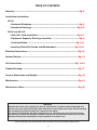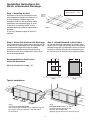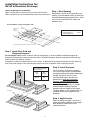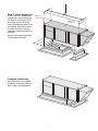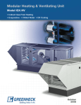
1
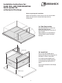
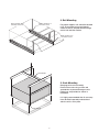
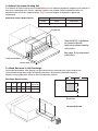
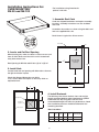
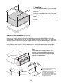
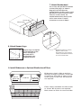
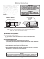
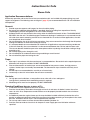
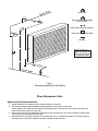
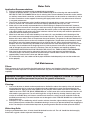
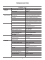
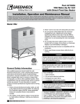
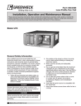
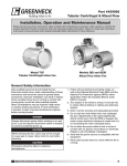
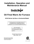
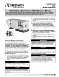
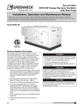
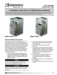
Part # 457502
Installation, Operation and Maintenance Instructions
for
Neutralizer 100% Outdoor Air Ventilators
WARNING:
Improper installation, adjustment, alteration, service or maintenance can cause property damage,
injury or death. Read the installation, operating, and maintenance instructions thoroughly before
installing or servicing this equipment.
This manual is the property of the owner, and is required for future maintenance.
Please leave it with the owner when you complete the job.
GREENHECK
®
P.O. BOX 410 SCHOFIELD, WISCONSIN 54476-0410
PH. 715-359-6171
June 1998
TABLE OF CONTENTS
Warranty ............................................................................................................Pg. 2
Installation Instructions:
NV-45
• Horizontal Discharge ................................................................................Pg. 3
• Downblast Discharge ............................................................................Pg. 4-5
NV-90 and NV-120
• Slab, Rail, Curb Installation...................................................................Pg. 6-7
• Equipment Supports, Discharge Locations ............................................Pg. 8
• Curb Installation .................................................................................Pg. 9-11
• Installing Filter/Coil Section and Weatherhood.................................Pg. 10-11
Electrical Instructions......................................................................................Pg. 12
System Startup.................................................................................................Pg. 13
Coil Instructions..........................................................................................Pg. 14-16
Trouble Shooting..............................................................................................Pg. 17
General Dimensions and Weights.....................................................................Pg. 18
Maintenance.....................................................................................................Pg. 19
Maintenance Notes...........................................................................................Pg. 20
Warranty
Greenheck warrants this equipment to be free from defects in material and workmanship for a
period of one year from the purchase date. Any units or parts which prove to be defective during
the warranty period will be repaired or replaced at our option.
The motor is warranted by the motor manufacturer for a period of one year. Should the motor
prove defective during this period, it should be returned to an authorized motor service station.
Greenheck will not be responsible for any installation or removal costs.
Due to continuing research, Greenheck reserves the right to change specifications without notice.
2
Installation Instructions for:
NV-45 w/Horizontal Discharge
A -Equip. Support CL
Step 1 Mounting the Unit
Arrangement HZ can be mounted on a curb
with an equipment support (see curb inst.) or
on three equipment supports (figs. 1&4).
441/4"
Equipment
Support
Footprint
Arrangement HZ can also be used for indoor
applications mounted hanging (fig. 5), inline
as part of an air handling system, or base
mounted. Mounting hardware to be provided
by others.
CL
A
A
(fig.1)
CL
CL
In any case, adequate support of the unit is
required.
Step 2 Attach Ductwork to Unit Discharge
Step 3 Attach Ductwork to Unit Intake
Chart and drawing (fig.2) below shows opening size (ID)
and location for a discharge collar. Also included is the
recommended straight duct length for optimal
performance. Greenheck recommends attaching
ductwork to collar using a rubber duct section at the
unit to eliminate vibration.
For non-weatherhood installations, fig. 3 below shows
dimensions for supply opening (ID). Attach ductwork to
perimeter flange using a rubber duct section at the unit
to eliminate vibration. Design the remaining ductwork
for minimal losses to allow the unit to operate properly.
16
Recommended Duct Size/Location
and Intake Dimensions
48
23
Minimum Straight Duct Length - 54”
43
16
12
(fig.2)
(fig.3)
Typical Installations
DISC
HARG
E
DISC
HARG
E
INTA
KE
INTA
KE
(fig.4)
Roof mounted arrangement HZ
with weatherhood, mounted on three equipment supports.
Ductwork is attached to discharge collar with rubber
boot transition.
3
(fig.5)
Arrangement HZ shown as an indoor
hanging installation with intake and
discharge ductwork installed.
(Hanging support structure for unit is by others).
Installation Instructions for:
NV-45 w/Downblast Discharge
Before beginning this installation:
Make sure that there is room to access the unit from all sides.
Make sure inlet of unit is located well away from any exhaust fans.
Step 1 Roof Opening
Determine the center of the supply duct roof
opening. The chart below shows the maximum
recommended roof opening dimensions. These
sizes can be smaller based on codes and
ductwork sizes.
For Installations using rectangular curb
Rectangular
Curb
Footprint
Roof
Opening
A
A/2
A - Max Roof Open. Sq.
Supply Duct CL to
B - Equip. Support CL
C*
C*
881/2"
A
A/2
CL
47"
C*
B
CL
*C- Determine equal dimension for these 3 locations
CL
Step 2 Install Roof Curb and
Equipment Support
For rectangular curbs, center curb on 3 sides of roof opening, as shown in above installation diagram, by
determining C dimension (varies per unit /curb size ). For either installation, level the curb and shim if necessary.
Attach curb to roof and flash in place.
If equipment support is needed, refer to chart in step 1 for dimensional location based on NV unit size. Attach to
roof in the same manner as the curb. Remove metal cover, flash to wooden nailer, and reinstall cover.
Recommended Supply
Ductwork Sizes
Straight
Duct
Duct
Size
Length
Supply
Ductwork
by Others
16 x 16
54"
Duct Adaptor
Ductwork
Sealant
Step 3 Install Ductwork
The chart shows at left shows the duct
sizes and straight lengths recommended
for optimal performance (AMCA Publication
201-90). Using duct sizes less then
recommended lengths will affect fan
performance. Good duct installation
practices should be followed for the
remaining ductwork. The use of a duct
adapter with the supply duct is strongly
recommended to properly align the
ductwork with the supply fan discharge.
The duct adaptor is only a guide and is not
intended to be used as support for the
ductwork.
Step 4 Apply Sealant
Before installing unit apply a sealant or a
gasket around the perimeter of the supply
duct adaptor to isolate the fan and
minimize vibration.
4
Step 5 Install Supply Unit
Use a crane and a spreader bar
hooked to the factory lifting lugs
(as shown in the diagram) to lift
and center the NV unit on the
curb and equipment support. Use
self-tapping sheet metal screws
to fasten unit to the curb and
equipment support through holes
provided.
Lifting Lugs
(4 places)
Model TSU
Supply Unit
Electrical and pipes connections
can be made at this time.
Complete Installation
Illustration shows the complete
installation of downblast NV with
filter section and weatherhood.
5
GREENHECK
Installation Instructions for:
®
SLAB, RAIL, AND CURB MOUNTING
NV-90 and NV-120
w/Horizontal Discharge
Before beginning this installation:
Make sure that there is room to access the unit from all sides.
Make sure inlet of unit is located well away from any
exhaust fans.
1a. Slab Construction
Recommended Size: 1ft. wider and
longer than total unit size.
Recommended Material: Concrete at
least 4" thick.
Slab should be set and leveled on a
sufficient bed of gravel for proper
drainage.
Spreader Bar
1b. Install Unit
Use a crane and spreader bar to
prevent damage to unit. Lifting lugs are
provided as shown in illustration.
NV
Un
it
Int
Its is highly recommended that all
accessory items be lifted separately
and attached after the NV unit is in
place.
ake
Unit may be fastened to slab through
lifting lugs.
Lifting Lugs (4)
6
2. Rail Mounting
Rails extends 6" from
discharge end of unit
Rails located 6-12" in
from sides of unit.
For proper support, rails should be located
6-12" in from sides of unit and should
extend at least 6" beyond both discharge
end of unit and filter section.
Rails extend 6" from
end of filter section
Spreader Bar
3. Curb Mounting
(See page 9 for curb assembly)
Install unit on curb using a crane and
spreader bar to prevent damage to unit.
Lifting lugs are provided as shown in
illustration.
It is highly recommended that all accessory
items be lifted separately and attached
after the unit is set in place.
Lifting Lugs (4)
7
4. Optional Up-stream Heating Coil
If an optional up-stream heating coil is provided with the unit an additional equipment support may be required. If
filters only are provided in this section, additional support is not needed. Follow the guidelines below for
determining the coil section support required. Page 18 lists unit weights for equipment support load
requirements.
Slab/Rail Mount
Curb Mount
NV-90
None
Curb Height
NV-120
12”
Curb Height + 12”
Equipment Support Requirements:
Coil Section
Typical NV-120 installation
on cement slab with
optional up-stream heating
coil section .
See page 10 for attachment
instructions.
Equipment Support
Cement Slab
5. Attach Ductwork to Unit Discharge
Chart and drawing below show opening size (ID) and location for discharge collar. Also included is the
recommended straight duct lengths for optimal performance. Greenheck recommends attaching
ductwork using a rubber duct section at the unit to eliminate vibration.
D
C
Discharge Opening Sizes
A
B
NV-90
161/4
24
NV-120
161/4 251/2
C
D
Straight
Duct Length
34 1/2 223/8
81
23 1/4
96
34
B
A
Str
Back View
aig
ht
Du
ct
Len
gth
NV-90 and NV-120
8
Installation Instructions for:
*For installations using Greenheck's
optional roof curb.
CURB MOUNTING*
NV-90 and NV-120
1. Assemble Roof Curb
Curbs are shipped knockdown and require assembly
by others. Assembly instructions are also included
with curb.
Assemble curb sections as shown using hex bolts and
lock nuts supplied with curb.
Detail shown is typical for all four corners.
Roof Curb
41/2
241/4
2. Locate and Cut Roof Opening
When locating unit, make sure there is room to access unit
from all sides. Make sure inlet of this unit is located well
away from exhaust fans.
Recommended
Roof Opening
(36"x36")
40 5/8
Roof Opening for NV-120 and NV-90 = (A) 36" x (B) 36"
103 1/2
3. Install Curb
Located curb over roof opening with dimensions shown to
the right and fasten in place.
43 1/4
Check that diagonal dimensions are within
± 1/8" of each other and adjust as necessary. Shim as
required to level.
813/16
A
B
4. Install Ductwork
D
Roof Opening
Ductwork
by Others
Roof Curb
C
The following chart shows the duct sizes and straight
lengths recommended for optimal performance (AMCA
Publication 201-90). Using duct sizes less than
recommended lengths will affect fan performance. Good
duct installation practices should be followed for the
remaining ductwork.
Duct Locations:
NV-90
NV-120
9
A
B
C
D
Straight
Duct Length
24
93/8
24
301/4
81
26
91/2
26
291/4
96
5. Install Unit.
Use a crane and spreader bar to prevent damage
to unit. Lifting lugs are provided as shown in
illustration.
It is highly recommended that all accessory items
be lifted separately and attached after the unit is
in place.
Electrical and pipe connections can be made at
this time.
6. Attach Filter/Coil Section (if included)
Use a crane and spreader bar hooked to factory
lifting lugs (as shown in diagram) to lift and center the filter section on the NV unit. Note that the top Ushaped flange on the filter section fits over the vertical flange of the NV unit (see detail A). Use sheet metal
screws to fasten the filter section to NV unit. Mounting holes are prepunched, see diagram for approximate
hole locations.
Filters ship separately. To install, remove side panel on filter section and slide into filter channels. Note
arrows on filters for correct orientation.
Note:
If the optional up-stream heating coil
section is included with the unit, special
support for this section is required. See
page 8 for requirements.
Spreader Bar
Lifting Lugs (2)
Detail A
Filter /Coil section fastener locations
typical for entire section.
Top fasteners are accessed from
outside, side fasteners are accessed
from inside, bottom fasteners are
accessed from underneath filter section
(Note: bottom fasteners are not required
for slab mounted units).
Fasten through
both flanges.
KSU Unit
Filter/Coil Section
Butt units together
10
7. Attach Weatherhood
Use a crane and spreader bar hooked
to factory lifting lugs (as shown in
diagram) to lift and center the
weatherhood on the filter section (same
procedure as shown in previous step).
If there is no filter section, the
weatherhood attaches directly to NV
unit in same manner. Fastener
instructions are same as Step 6.
Spreader Bar
Lifting Lugs (2)
8. Attach Support Legs
Support Legs (2)
Support Legs are required
on weatherhood section.
Attach through prepunched holes in
weatherhood using
supplied fasteners.
Weatherhood fastener locations
typical for entire section.
Top fasteners are accessed from
outside, side and bottom fasteners
are accessed from inside.
9. Install Birdscreen or Optional Weatherhood Filters
Install 1stslide to side
Install last
Birdscreens simply slide up and into
opening, resting on channels. Install side
screens first and slide to edges of unit.
Install center screen last. No fasteners
are required.
Install 2ndslide to side
Filters simply side down into filter tracks
as shown. No fasteners are required.
Note arrows on filters for correct airflow.
11
Electrical Instructions
Before connecting power to the unit, read and
understand the following instructions and
wiring diagrams. Complete wiring diagrams
are attached inside the door(s) of the unit.
All wiring should be done in accordance with
the National Electrical Code ANSI/NFPA 70latest edition and any local codes that may
apply. In Canada, wiring should be done in
accordance with the Canadian Electrical
Code. The equipment must be properly
grounded.
CAUTION !
If any of the original wire must be replaced,
the replacement wire must have a temperature
rating of at least 105°C, except for energy cut-off
or sensor lead wire which must be 150°C.
DANGER !
High voltage electrical input is needed for this
equipment. This work should be performed by a
qualified electrician.
Electrical Controls Door
Electrical Location
Electrical Power
Connection
Electrical Power Connection
Electrical Controls Door
NV-45
NV-90-120
NOTE: Any wiring running through the NV unit in the airstream must be protected by
flexible metal conduit, metal clad cable, or raceways.
Sequence for wiring NV unit:
For units without control centers:
The motor nameplate is to be used for determining the voltage and amperage required by
the unit.
For units with control centers:
1. The unit’s nameplate states the voltage and total amperage required.
The main feeder supplying power to the unit should be sized for the label’s voltage and amperage.
2. The main power line should be connected to the disconnect switch.
Make sure that the disconnect lugs are securely tightened.
3. Connect control panel wiring to terminal strip in the control center.
Greenheck’s standard control voltage is 120/60/1.
4. When an optional convenience outlet is provided, a separate power supply must be provided to
the receptacle. This circuit must be on a ground fault breaker.
CAUTION
Any wiring deviations may result in personal injury or property damage. Greenheck is not
responsible for any damage to, or failure of the NV unit caused by incorrect final wiring.
12
SYSTEM STARTUP
For proper unit function and safety, follow everything in this startup procedure in the order presented. This is to
be done after the electrical connections are complete.
Special Tools Required
• Voltage meter
• Incline manometer or equivalent
• Tachometer
• Thermometer
• Amperage meter
1. Check Voltage
Before starting the unit compare the supplied voltage with the unit’s nameplate voltage and the motor
voltage.
2. Check Blower Rotation
Blower
Housing
t
Ro
on
a ti
First hand rotate the blower to ensure that the wheel is not rubbing against
the scroll. If the blower is rotating in the wrong direction, the unit will move
some air but not perform properly. To check the rotation, open the blower
access door and run the blower momentarily to determine the rotation. To
reverse the rotation, turn the power off and use the following procedure:
• For single phase units, rewire the motor per the instructions on
the motor.
• For three phase units, interchange any two power leads.
This can be done at the motor starter.
3. Air Volume Check and Measurement
Along with the building balance, the units air volume (cfm) should be measured and compared with its rated air
volume. This unit is flexible for varying air volume (units above 15 Hp may have fixed drives), but the actual air
volume should be known for making final adjustments.
The most accurate way to measure the air volume is by using the pitot traverse method in the ductwork away
from the blower. Other methods can be used but should be proven and accurate.
To adjust the air volume, change the fan RPM or the system losses. See Trouble Shooting Section in this
guide.
4. Measure Motor Voltage, Amperage and Fan RPM
All access doors must be installed except the control center door. Measure and record the input voltage and
motor amperage(s).
To measure the fan RPM, the blower door will need to be removed. Minimize measurement time because the
motor may over amp with the door removed.
With blower door in place compare measured amps to the motor nameplate full load amps and correct if
overamping. See the trouble shooting section in this guide.
5. Settings for Optional Components
Freeze Protection:
This de-energizes the blower if the output temperature is below the set point. A timer allows the blower to
operate during startup. This will reset when turned off.
Typical settings are:
Discharge temperature = 35°F
Timer = 5 minutes
13
Instructions for Coils
Steam Coils
Application Recommendations:
Satisfactory operation and service life are best ensured when coils are installed with proper piping, trap, and
support arrangement. The following notes and figure 1 (page 15) are recommended for the coil unit installation
and operation.
General:
1.
2.
3.
4.
5.
6.
7.
8.
Provide separate supports and hangers for the unit and the piping.
Be certain that adequate piping flexibility is provided. Stresses resulting form expansion of closely
coupled piping and coil arrangement can cause serious damage.
Standard steam coils are pitched in the casings when installed for horizontal air flow. The CASING MUST
BE LEVEL after the unit is installed for proper condensate drainage. If condensate is not removed the coil
will suffer from water hammering and will have a shortened life. On vertical air flow applications, the coils
must be pitched when installed.
Do not reduce pipe size at the coil return connection. Carry return connection size through the dirt pocket,
making the reduction at the branch leading to the trap.
It is recommended that vacuum breakers be installed on all applications to prevent retaining condensate
in the coil. Generally, the vacuum breaker is to be connected between the coil inlet and the return main.
The vacuum breaker should be open to the atmosphere and the trap design should allow venting of large
quantities of air.
Do not drip supply mains through the coil.
Do not attempt to lift condensate when using modulating or on-off control.
Do not reduce the pipe size leaving the coil.
Traps:
1.
2.
3.
4.
Size traps in accordance with the manufacturer’s recommendations. Be certain that the required pressure
differential will always be available. DO NOT UNDERSIZE.
Float and thermostatic or bucket traps are recommended for low pressure steam. On high pressure
systems, bucket traps are normally recommended. The thermostatic traps should be used only for air
venting.
Bucket traps are recommended for use with on-off control only.
Locate traps at least 12 inches below the coil return connection.
Controls:
1.
2.
On high pressure installations, a two-position steam valve with a face and bypass
arrangement is preferred where modulating control is required.
Modulating valves must be size properly. DO NOT UNDERSIZE.
Freezing Conditions (Entering air below 35o F):
1.
2.
3.
4.
5.
5 PSI steam must be supplied to the coil at all times.
Provision should always be made to thoroughly mix fresh air and return air before it enters the coil on
return air units. Also, temperature control elements must be properly located to obtain true air mixture
temperatures.
As additional protection against freeze-up, the trap should be installed sufficiently far below the coil to
provide an adequate hydrostatic head to ensure removal of condensate during an interruption in the steam
pressure. Estimate 3 feet for each 1 PSI of trap differential required.
On start up, admit steam to coil ten minutes before admitting outdoor air.
Provision must be made to close fresh air dampers if steam supply pressure falls below minimum
specified.
14
m
Stea
n
Mai
Gate Valve
Control Valve, Modulating
Two-Position
Check Valve-Vacuum Breaker
Float and Thermostat Trap
Strainer
Greenheck does not
supply coil controls, all
control elements shown
are supplied by others.
Retur
n Mai
n
Figure 1
Recommended Steam Coil Piping
Direct Expansion Coils
Application Recommendations:
1.
2.
3.
4.
Piping should be in accordance with accepted industry standards.
The condensate drain pipe should be sized adequately to ensure the condensate
drains properly. The bottom of the drain pan should be twice the distance of the internal static pressure
water column above the exit of the trap.
When connecting suction and liquid connections make sure the coil is free from all foreign material. Make
sure all joints are tight and free of leakage.
Greenheck does not supply compressor or condensing units, for further instruction on DX coil installation
and operation contact your compressor and/or condenser manufacturer.
15
Water Coils
Application Recommendations:
1.
2.
3.
4.
5.
6.
7.
Piping should be in accordance with accepted industry standards.
Connect the WATER SUPPLY TO THE BOTTOM CONNECTION on the air leaving side and the WATER
RETURN TO THE TOP CONNECTION on the air entering side. The extra bottom connection can be used for
an auxiliary manual drain connection, and the extra top connection can be used for an automatic air vent or
the extra connections can be capped. Connecting the supply and/or return in any other manner will result
in very poor performance.
The air vent at the uppermost point should be temporarily opened during system start-up to release all
of the air from the coil. To maintain heat transfer capacity, periodically vent any air in coil.
Water coils are not normally recommended for use with entering air temperatures below 40oF; however,
special high pressure water coils have been used successfully on high temperature hot water jobs with low
entering air temperatures when correctly controlled. No control system can be depended on to be 100%
safe against freeze-up with water coils. Glycol solutions or brines are the only safe media for operation of
water coils with low entering air conditions.
When fresh and return air are to be heated by a hot water coil, care should be used in the design of the
duct work to ensure thorough mixing before the air enters the coil. The return air should always enter the
bottom of the duct and the fresh air should enter the top of the duct. The greater the distance between the
mixing point and the entrance to the coil, the better the application. Temperature control elements should
be located to sense the lowest temperature air that will enter the coil. Always install gasketed fresh air
dampers which are automatically controlled to close whenever the water leaving the coil is too cool, or the
fan stops. Care should be used in designing fresh air intake to prevent stack effect (or wind) from forcing
cold air through the coils when the fan is shut down. Two sets of dampers are frequently required.
CONTINUOUS WATER CIRCULATION THROUGH THE COIL AT ALL TIMES IS HIGHLY RECOMMENDED.
Pipe sizes for the system must be selected on the basis of the head (pressure) available from the
circulation pump. The velocity should not exceed 8 feet per second and the friction loss should be
approximately 3 feet of water column per 100 feet of pipe.
For chilled water coils, the condensate drain pipe should be sized adequately to ensure the condensate
drains properly.
Coil Maintenance
Filters:
Filters upstream of the coil should be checked regularly for dirtiness and clogging. If the filters are dirty, they
should be cleaned or replaced. It is important that the coils stay clean to maintain maximum heat transfer
capability.
WARNING: Biological Hazard! All drain pans and coils should be cleaned on a regular
schedule by qualified personnel to prevent the growth of bacteria.
Cleaning:
1.
2.
Coils must be clean to obtain maximum performance. Soiled fins reduce the capacity of the coil, demand
more energy from the fan, and create a medium for order and bacteria to grow and spread through the
conditioned zone. High pressure water (700 Psi or less) may be used to clean coils with fin thickness over
.0095 inches thick. TEST THE SPRAY PRESSURE over a small corner of the coil to determine if the fins will
withstand the spray pressure. For coils with fragile fins or high fin density, foaming chemical sprays and
washes air available. Many coil cleaners contain harsh chemicals, so they must be used with caution by
qualified personnel only. Care must be taken not to damage the coils. FINS ARE SHARP! Use caution when
working with coils.
Drain pans in any air conditioning unit will contain moisture; therefore, algae and other organisms will grow
due to airborne spores and bacteria. Scheduled cleaning is necessary to prevent build-up from clogging the
drain. The drain pans should also be kept clean to prevent growth of bacteria and the spread of disease.
Winterizing Coils:
During any extended down time, all water should be drained from the coil. The coil should then be thoroughly
flushed with a glycol solution to prevent freeze damage.
16
TROUBLE SHOOTING
Blower Unit
Symptom
Blower fails
to operate
Motor overamps
Insufficient airflow
Possible Cause
Corrective Action
Blown fuse or open circuit breaker
Replace fuse or reset circuit breaker and
check amps
Broken fan belt
Replace
Defective motor or capacitor
Replace
Motor starter overloaded
CFMs too high
Static pressures are higher or lower
than design
Blower rotation is incorrect
Motor voltage incorrect
Motor horsepower too low
Reset starter and check amps
Check CFMs and adjust drives if needed
If higher, ductwork should be improved
If lower, fan RPMs should be lower
Check rotation and correct
Check motor nameplate and supplied voltage
See specifications and catalog for fan
curves to determine if horsepower is sufficient.
Replace motor.
Adjust damper linkage or replace
damper motor
Shorted windings in motor
Unit damper not fully open
System static pressure too high
Improve ductwork to eliminate losses
using good duct practices
Blower speed too low
Check for correct drives and RPMs
with catalog data
Open and adjust
Clean or replace
Repair
Dampers or registers closed.
Dirty or clogged filters
Leaks in ductwork.
Too much airflow
Excessive noise
or vibration
Elbows, or other obstructions
may restrict fan outlet.
Belt slippage
Correct or improve ductwork
Blower fan speed too high
Check for correct fan RPM
Filter(s) not in place.
Install filters
Insufficient static pressure (SP)
(airflow resistance)
Induce SP into system ductwork.
Wheel rubbing on housing
Center wheel
Loose wheel on shaft
Tighten wheel setscrew
Loose motor or blower sheave
Tighten sheave setscrew
Belts too loose
Adjust belt tension after 24 hours
of operation
Loosen to maintain 3/8” deflection
per ft. of span between sheaves
Adjust belt tension
Belts too tight
Worn belt
Replace
Motor base or blower loose
Tighten mountings bolts
Worn bearings
Replace
Bearing and drive alignment
Realign
Motor out of balance
Replace
Wheel out of balance
Replace or rebalance
Sheaves eccentric or out of balance
Replace or rebalance
Accumulation of material on wheel
Clean wheel and housing
17
General Dimensions and Weights
Optional Filters
128
NV-45
1680 lbs
NV-45 w/Heating Coil
1780 lbs
NV-90
2650 lbs
NV-120
3150 lbs
NV-90 w/Heating Coil
2870 lbs
NV-120 w/Heating Coil
3370 lbs
NV-90/120
Weatherhood
250 lbs
NV-90/120
Filter Section
200 lbs
NV-90/120
Filter Section w/Coil
420 lbs
30
46
Optional Weatherhood
Optional Motorized
Damper
ELEVATION VIEW
52
Motor Control
Center
Optional
Heating Coil
Optional Heating Coil
Heat Pipe
Cooling Coil
PLAN VIEW
Optional Inlet
Damper
88
501/2 (NV-90)
62 (NV-120)
461/4
17
501/2
Optional
Weatherhood
Blower/Motor
Access Door
ELEVATION VIEW
Optional Curb
or Support
Optional
Filter/Heating
Section
Cooling Coil
Optional Heating Coil
Motor
Control
Center
1101/2
Heat Pipe
PLAN VIEW
18
Maintenance
Greenheck recommends these procedures to insure trouble free operation of this unit. Most unit failures can be
attributed to poor setup or poor maintenance.
A record of maintenance performed on this unit should be kept. This information will provide essential information
if problems are encountered. A section at the back of this manual is provided for recording the unit's maintenance
history.
2 weeks after startup
Check belt tension - Belts tend to stretch after a period of
time. They should be periodically checked for wear and
tightness. Approximately 3/8" of deflection per ft. of span
between sheaves is standard for belt tightness. When
replacing belts, use the same type as supplied with the unit.
Matched belts should always be used on units with
multigroove pulleys.
Motor
Blower
Housing
Rotation
CAUTION: When performing any maintenance on this
unit be sure that the power is disconnected and cannot
be accidently turned on. The control center disconnect
can be locked in the off position .
Too Tight
Belt Tension
Adjustment
Screw
Too Loose
NOTE: For motors of 1 HP or less a smaller sliding base
bracket is used to attach to blower.
Replacement of belts - should be accomplished by loosening the tensioning device to the point where the belts
can be removed by hand. Do not force belts on or off as this may cause breakage of cords leading to premature
belt failure. Belts should be adjusted as shown above.
Every 3 Months
The filter in the unit should be inspected at least every 3 months. Depending on the environment filters could
require changing or cleaning more or less often. The filters can be slid out of either side of the unit.
If washable filters are installed, they can be washed in warm soapy water. An adhesive spray can be applied to
increase filter efficiency.
If disposable filters are installed, check by holding up to a light source. If light cannot pass through the filter, it
should be replaced. Replacement filters should be of the same manufacturer and size.
When reinstalling filters, be sure to install with the airflow in the correct direction indicated on the filter and with
any factory spacers that came with the unit.
Yearly
All bearings on units 108 to 118 are permanently lubricated and require no further lubrication under normal use.
Normal use being considered -20°F to 120°F and in a relatively clean environment. Units from sizes 120 to 220
should be checked monthly for lubrication.
Motor maintenance is generally limited to cleaning and lubrication (where applicable). Cleaning should be limited
to the exterior surfaces only. Removing dust and grease buildup on motor housing assures proper motor cooling.
Greasing of motors is intended only when grease fittings are provided. Many fractional motors are permanently
lubricated and require no further lubrication. Motors supplied with grease fittings should be greased in
accordance with manufacturer's recommendations. When motor temperature does not exceed 104°F (40°C), the
grease should be replaced after 2000 hours of running time as a general rule.
Wheels require very little attention when moving clean air. Occasionally oil and dust may accumulate on the wheel
causing imbalance. When this occurs the wheel and housing should be cleaned to assure smooth and safe
operation.
Routinely check all fasteners for tightness.
19
Maintenance Documentation
Job Information
Job Name:________________________________________
Address: _________________________________________
City: ________________ State: ________ Zip: __________
Phone: __________________ Fax: ____________________
Contact Person: ___________________________________
Service Organization: ______________________________
Address: _________________________________________
City: ________________ State: ________ Zip: __________
Phone: __________________ Fax: ____________________
Work Done By: ____________________________________
Name Plate Information
Model: ___________________________________________
Volts: ___________ Hertz: __________ Phase:__________
Amps: __________________ Mark: ___________________
Supply Hp: _______________________________________
Serial Number: ____________________________________
Field Start-Up Documentation
Actual Voltage:
Hertz:
Phase:
Motor Voltage:
Actual Amperage:
Motor Amperage:
Fan RPM:
Blower Rotation
❏ Correct
Air Volume
Design
Actual
CFM
CFM
Maintenance
Date
Time
Notes:
20
NV-IOM-R