1
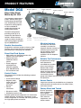
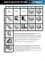
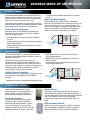
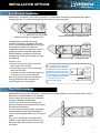
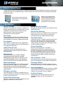
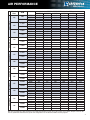
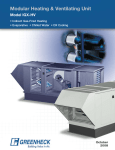
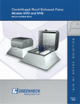
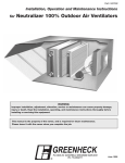
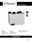
Modular Make-Up Air Unit
Model DGX
• Direct Gas-Fired Heating
• Evaporative • Chilled Water • DX Cooling
March
2007
PRODUCT FEATURES
Model DGX
Module 1, Option 2
Module 2, Option 2
Module 4, Option 1
Direct Gas-Fired
Make-Up Air Unit
Module 5, Option 2
The Greenheck model DGX is
a 100% efficient direct gasfired heating and ventilating
unit. Chilled water, DX, and
evaporative cooling options
are also available for
combination heating and
cooling requirements.
The DGX is designed for
providing make-up air to
commercial and industrial
facilities. Airflow volumes
range from 800 to 48,000 cfm
with heating output capacities
up to 4,800,000 Btu/hr.
Direct GasFired Heat
DGX shown with optional birdscreen
weatherhood, V-bank filter section
and horizontal fan discharge.
Durable Construction
Designed for maximum weather resistance, DGX
housings are constructed of heavy gauge G90
galvanized steel. Lifting lugs are standard.
Direct Gas-Fired System
• High quality cast aluminum burners with
stainless steel mixing plates
• Maxitrol electronic
modulation burner
control
• Flame safeguard
with digital fault
indicator capability
(over 400,000 Btu/hr)
• 25:1 turn down ratio
Control Center
The control center includes the following standard
components:
• 24 volt control voltage
• Magnetic motor
starter with solid
state overload
protection
• Control
transformer
• Disconnect switch
• Distribution terminal strip
Premium grade control components are selected for
reliable operation. All electrical components are UL
Listed, recognized, or classified, and factory prewired
for single point power connection.
2
Vibration Isolators
The entire fan and motor
assembly is mounted on
neoprene vibration isolators to
minimize noise transmission
into the building. Spring
vibration isolators are
available in lieu of neoprene
isolators.
Reliable Fan Performance
Air performance ratings
from Greenheck’s
accredited test chamber
ensure accurate data.
Double width, double
inlet forward curved
wheels for high efficiency
and low sound levels are
constructed of heavy
gauge steel. Wheels are balanced to ensure vibration
free operation.
Access Panels
Large access panels are provided for easy inspection
and maintenance of motors, drives, fan wheels, filters,
and heater controls.
Factory Wired and Tested
All units are tested
prior to shipment to
ensure proper
operation of the gas
train, electrical
components, and
airflow controls.
MODULE SELECTION OPTIONS
None
requires
Module 2, Option 2
Module 2
FILTER
Module 3
COOLING
None
None
Module 4
HEATING
Module 5
DISCHARGE
Direct Gas Furnace
100% Outdoor Air
Downblast
Discharge
Option 2
Option 1
Module 1
INTAKE
V-Bank Filters
Pleated or
Aluminum Mesh
*Cooling Coil – CW, DX
(standard capacity)
Direct Gas Furnace
Recirculation - requires
Module 2, Option 3
Horizontal
Discharge
Filtered
Weatherhood
80/20 Filtered
Recirculation
*Cooling Coil – CW, DX
(high capacity)
Direct Gas Furnace
Variable Air Volume
Upblast
Discharge
Option 4
Option 3
Birdscreen Weatherhood
requires
Module 2, Option 2
Louvered
Weatherhood
*Chilled water or direct expansion (DX) cooling is available with the model DGX. The cooling section
includes the cooling coil, sloped stainless steel drain pan and insulated double wall construction.
Drain and coil connections are stubbed through the wall for convenience.
For proper coil sizing, use Greenheck CAPS selection software or contact your local representative.
Four row and six row chilled water or DX coils are available with airflow capacity up to 11,000 cfm.
Cooling coil sections are installed upstream of the fan section for a draw through arrangement and
provide a streamlined transition to adjacent DGX sections. DX coils require remote condensing units.
Option 5
• Module 2 is not available with the Evaporative Cooler section (Module 1, Option 6)
• Cooling Coil modules (Module 3, Option 2 & 3) are not available with Recirculation (Module 2,
Option 3)
• Optional intake dampers available on Cooling Coil section (Module 3, Option 2 & 3)
• Module 1, Option 3, 4 & 5 are not available on Housing 35 and larger
Option 6
Thru-Wall
Evaporative
Cooling
The evaporative cooling section includes a galvanized steel housing with a louvered intake, 2 inch
aluminum mesh filters and a stainless steel evaporative cooling module. The evaporative cooling
media has a depth of 12 inches for 90% cooling effectiveness.
The entire section mounts directly to the front of the DGX unit, eliminating transition or ductwork
by others. Drain and overflow are conveniently tapped through the side of the cooling section. The
supply line connection is field located where convenient. Freeze protection, automatic drain & fill, and
water economizer (Water Wizard) options are also available.
Airflow capacity for evaporative cooling is up to 46,000 cfm. The evaporative cooling section for the
housing 32 and larger ship separately.
3
VARIABLE MAKE-UP AIR OPTIONS
Variable Volume
The variable volume option is recommended when a
building’s exhaust volume will vary. The make-up air
volume will track with the exhaust volume, providing
only the necessary amount of make-up air.
The variable volume option saves energy by reducing
both fan power and gas consumption whenever makeup air requirements are less than the maximum.
Airflow Control Strategies
Greenheck offers four methods of controlling the
make-up air volume. All four vary the fan speed for
maximum energy savings.
• Variable Frequency Drive controlled by building
pressure.
• Variable Frequency Drive controlled manually with a
remote potentiometer.
• Variable frequency drive controlled by a 2-10 VDC
or 4-20 mA signal.
• 2 speed motor controlled manually with a remote
switch.
Burner By-Pass Damper
The Variable Volume option includes a patented
burner by-pass damper, which maintains the pressure
drop across the burner as air volumes change. This
assures that complete and proper combustion occurs.
The by-pass damper is self-adjusting, designed for
minimal maintenance, and requires no controls.
Outside Air
Supply Air
Recirculation
The recirculation option is recommended when the
ventilation equipment provides the primary source of
heating for the space.
Up to 80% of the air from the space can be
recirculated and filtered and then combined with a
minimum of 20% outdoor air for a continuous source
of fresh air. Only outdoor air is used for combustion to
eliminate the possibility of contaminants from the
recirculated air crossing over the burner.
• Modulating actuator controlled manually with a
remote potentiometer.
• Modulating actuator controlled by a 2-10 VDC or
4-20 mA signal.
• Two position actuator controlled manually with a
remote switch/time clock.
20%
Airflow Control Strategies
Greenheck offers four methods of controlling the ratio
of recirculated air to outdoor air via motorized
dampers.
• Modulating actuator controlled by building pressure.
80-0%
Outside Air
(100-20%)
Recirculated Air
(0-80%)
Supply Air
Temperature Control
There are three temperature control
options for heat: 1) Discharge Control, 2)
Space Control, and 3) DDC Interface
Control. Cooling controls are by others.
Discharge Control
A factory installed modulating system
controls the gas valve to provide the
desired temperature based on a sensor
at the fan discharge. A room override
option is available to boost the discharge
temperature when the space is too cool.
4
Room Control
Specify this option when the DGX has the primary
responsibility for controlling the room temperature. A
manually adjusted room thermostat provides feedback
to the unit controls, which vary the discharge
temperature in order to maintain desired room set
point.
DDC Interface Control
Allows for an external signal (0-10 VDC or 4-20 mA)
from the building management system to modulate
the burner output to satisfy monitored conditions.
INSTALLATION OPTIONS
Roof Mounted Installation
Model DGX is available for stand alone installations as shown below. Downblast (Arrangement DB), upblast
(Arrangement UB), or horizontal (Arrangement HZ) discharge may be specified.
Upblast Discharge - Arrangement UB
Horizontal Discharge - Arrangement HZ
The Greenheck combination package
simplifies installation and reduces field labor
costs. The pre-engineered design ensures that
the supply fan, exhaust fan, curb, and
combination extension components interface
properly for kitchen ventilation applications.
Equally important, Greenheck combination
packages are specifically designed to comply
with NFPA 96.
NFPA 96 states:
• Exhaust duct must terminate at least 24
inches above the roof deck
• Fan discharge must be at least 40 inches
above the roof deck
• Air intake shall have a horizontal separation
of 10 feet from the exhaust discharge
Note: Consult local codes and the authority
having jurisdiction if there are questions
concerning the use of this product.
Combination Package - Arrangement DBC
The combination curb extension
is the component that pulls the
Combination Package together,
providing a factory engineered
interface between the roof curb
and the fans. It is also designed
to satisfy NFPA 96 requirements
- above the roof line - for
kitchen hood exhaust.
Thru-Wall Installation
Model DGX (Housing 12, 22, & 32 only) is available with a pre-engineered thru-wall installation option, which is
ideal when a roof penetration is not desirable.
Factory options that facilitate easy installation
and ensure problem-free operation:
Weatherhood: A full down turn design with
generous intake area to minimize intake velocity
and moisture entrainment.
Thru-Wall Sleeve: Sleeve provides attachment
interface between weatherhood and burner
section. Accommodates walls up to 15 inches in
depth.
Filter Section: Aluminum mesh media filters
outdoor air and strips fine mist from the air. A
drain pan weeps moisture out the front of the
wall sleeve.
5
ACCESSORIES
Remote Control Panels
A wide variety of remote control panels are available. Specify the desired combination of switches, thermostats,
temperature selectors and indicator lights. A terminal strip at the unit control center and remote panel simplify
field control wiring.
Basic remote control panel with
thermostat for room temperature
control option.
Kitchen style remote panels
feature toggle switches and a
stainless steel face plate for
flush mounting to a wall. The
junction box is also included.
Accessories
Special Coatings
Spring Vibration Isolation
Greenheck’s Permatector™ coating is available for a
durable, long lasting finish. Decorative paints are also
available in a variety of colors to match existing
building fixtures. Consult your Greenheck
representative for paint selections.
Spring blower vibration isolators are available in lieu of
neoprene isolators.
Roof Curbs
Factory provided roof curbs are available to ensure
compatibility between the make-up air unit and roof
curb. Standard construction is G90 galvanized steel.
Duct Adapter
Duct adapter is available with factory supplied roof
curbs. The duct adapter allows for easy alignment of
the supply duct connection.
V-Bank Filter Section
V-bank filter sections are available with 2-inch
washable aluminum mesh or 2-inch 30% efficient
disposable filters.
Weatherhood
Three weatherhoods are available: standard
weatherhood includes birdscreen, filtered
weatherhood includes aluminum mesh filters, and
louvered intake hood includes a drainable blade
louver at intake with 2-inch aluminum mesh filters.
Exhaust Fan Starter(s)
Exhaust fan starters are available factory mounted and
wired. Exhaust fan starters allow for an electrical
interlock between the supply and exhaust fan(s).
Dirty Filter Switch
A dirty filter switch is available to monitor the pressure
drop across the filter section. If the pressure drop
across the filters is higher than the field adjustable
setting, the dirty filter switch trips indicating the need
to clean or replace the filters.
Freeze Protection
Electronic freeze protection is available to
automatically shut down the supply fan when the
discharge temperature is below the adjustable set
point for an extended amount of time. This prevents
the unit from discharging non-tempered air into the
building and freezing pipes and other temperature
sensitive items.
Inlet Air Sensor – Heat
The heating inlet air sensor will automatically turn the
heat on and off based on the outdoor air temperature.
Motorized Dampers
Discharge Diffuser
Intake or discharge dampers are available to prevent
backdrafts when the supply fan is not in operation.
Intake dampers are factory mounted and wired.
Discharge dampers ship loose for field mounting in the
supply air duct.
Discharge diffusers are available as either 3-way for
horizontal discharge or 4-way for downblast discharge.
Fiberglass Insulation
One inch fiberglass insulation is available to line the
housing to prevent the formation of condensation and
to form an acoustical barrier.
Double Wall Construction
An interior metal liner is available to isolate the 1-inch
fiberglass insulation from the airstream.
6
Service Receptacle
A 115 volt GFCI outlet is mounted externally in a NEMA
3R box for the convenience of service personnel. A
separate 115 volt power source is required.
Auxiliary Contacts
Normally open and normally closed contacts are
available for supply fan status and supply fan
interlocks.
AIR PERFORMANCE
Blower
Size
CFM
800
108
Housing 12
1,200
1,500
109
2,400
2,000
110
3,000
Housing 22
2,600
112
4,400
4,000
115
6,500
Housing 32
6,500
118
9,500
10,000
120
15,000
Housing 35
15,000
122
19,000
19,000
125
23,000
Housing 38
24,000
127
30,000
26,000
130
34,000
Housing 42
32,000
133
40,000
42,000
136
48,000
RPM
BHP
RPM
BHP
RPM
BHP
RPM
BHP
RPM
BHP
RPM
BHP
RPM
BHP
RPM
BHP
RPM
BHP
RPM
BHP
RPM
BHP
RPM
BHP
RPM
BHP
RPM
BHP
RPM
BHP
RPM
BHP
RPM
BHP
RPM
BHP
RPM
BHP
RPM
BHP
RPM
BHP
RPM
BHP
RPM
BHP
RPM
BHP
RPM
BHP
RPM
BHP
0.75
1109
0.26
1347
0.59
1014
0.45
1216
1.1
912
0.59
1097
1.4
761
0.7
939
2.1
681
1.3
850
3.5
609
2.1
736
4.9
590
4.0
763
10.9
605
8.3
720
15.2
563
9.8
643
15.9
451
11.6
525
19.6
454
21.5
371
15.7
426
27.1
405
27.7
447
39.0
TOTAL
1.00
1216
0.31
1445
0.68
1140
0.54
1306
1.3
1013
0.71
1172
1.6
853
0.9
1006
2.4
756
1.5
906
3.9
668
2.5
783
5.4
634
4.5
795
11.6
637
8.9
746
16.1
594
10.7
671
16.9
478
13.0
548
21.4
412
12.5
477
23.1
397
17.5
448
29.1
426
29.8
465
41.5
PRESSURE
1.25
1311
0.35
1530
0.75
1255
0.63
1397
1.4
1110
0.08
1244
1.7
934
1.0
1073
2.6
822
1.8
960
4.3
724
2.8
827
5.9
678
5.0
829
12.3
667
9.6
771
17.0
625
11.7
967
18.0
504
14.3
571
23.2
440
13.9
499
24.8
422
19.2
470
31.5
445
32.0
483
44.0
in inches WG
1.50
1.75
1399
0.40
1361
1460
0.73
0.84
1484
1569
1.6
1.7
1199
0.10
1315
1386
1.9
2.1
1009
1.2
1137
1197
2.9
3.1
892
2.1
1013
1062
4.7
5.1
777
3.2
872
914
6.4
6.9
723
765
5.6
6.1
861
892
13.1
13.8
698
727
10.4
11.1
796
821
17.8
18.6
655
683
12.8
13.8
723
748
19.2
20.4
530
554
15.8
17.2
593
613
24.9
26.6
467
494
15.2
16.8
519
542
26.4
28.3
446
467
21.0
22.6
491
512
33.7
35.8
464
482
34.1
36.3
500
46.4
-
2.00
1648
1.9
1455
2.2
1254
3.3
1110
5.5
954
7.4
803
6.6
921
14.5
755
11.9
845
19.4
711
14.8
578
18.6
520
18.3
488
24.3
531
37.9
499
38.5
-
Note: The air performance data shown does not include internal static pressure losses due to items such as filters, dampers, and coils. For
exact air performance data based on specific unit configuration, use the Greenheck CAPS selection program.
7
Typical Specifications
General: Make-up air unit shall be as manufactured by
Greenheck or approved equal provided all specifications are
met. Greenheck Model DGX equipment is used as the basis of
design. Performance to be as scheduled on plans. Make-up air
unit shall be ETL listed to ANSI Z83.4 -1999, CSA 3.7 - M99 (for
100% outdoor air) or ANSI Z83.18-2000 (for recirculation).
Gas Train and Controls: Direct gas-fired system shall have
a draw through design and field adjustable burner baffles.
Gas trains up to 400,000 Btu/hr shall include a direct spark
ignition system. Gas trains greater than 400,000 Btu/hr shall
include a pilot ignition system and shall have digital coded
fault indicator capability. Fault indicator shall provide service
history by storing codes for the last five faults. Dual safety
shutoff valves shall be industrial duty and use 120 VAC control
signals. Temperature control shall incorporate a Maxitrol
electronic modulation control system.
Unit Casing and Frames: Unit shall be of internal frame type
construction of galvanized steel. All frames and panels shall
be G90 galvanized steel. Where top panels are joined there
shall be a standing seam to insure positive weather protection.
All metal-to-metal surfaces exposed to the weather shall be
sealed, requiring no caulking at job site. All components shall
be easily accessible through removable doors.
Insulation: Unit casing to be lined with 1 inch fiberglass
insulation where specified. Insulation shall be in accordance
with NFPA 90A and tested to meet UL 181 erosion requirements.
Double wall shall be provided where specified.
Fan Section: Centrifugal fans shall be double width, double
inlet. Fan and motor shall be mounted on a common base and
shall be internally isolated. All blower wheels shall be balanced.
Ground and polished steel fan shafts shall be mounted in
permanently lubricated ball bearings or ball bearing pillow
blocks. Bearings shall be selected for a minimum (L10) life in
excess of 100,000 hours at maximum cataloged speeds.
Motors and Drives: Motors shall be energy efficient,
complying with EPACT standards, for single speed ODP
and TE enclosures. Motors shall be permanently lubricated,
heavy duty type, matched to the fan load and furnished at the
specified voltage, phase and enclosure. Drives shall be sized
for a minimum of 150% of driven horsepower. Pulleys shall
be cast and have machined surfaces, 15 horse power and less
shall be supplied with an adjustable drive pulley.
Electrical: All internal electrical components shall be prewired
for single point power connection with exception of the larger
evaporative cooling sections. All electrical components shall
be UL listed, recognized or classified where applicable and
wired in compliance with the National Electrical Code. Control
center shall include motor starter, control circuit fusing,
control transformer for 24 VAC circuit,
integral disconnect switch and terminal
strip. Contactors, Class 20 adjustable
overload protection and single phase
protection shall be standard.
Filter Section: Filter section shall be
designed such that velocities across
the filters do not exceed 550 feet per
minute. Filters shall be 2-inch washable
aluminum mesh or 2-inch disposable.
Weatherhood: Weatherhood shall be
constructed of G90 galvanized steel
with birdscreen mounted at the intake.
Recirculation (optional): Recirculation
airflow shall be controlled by adjustment
of return damper position. Input signal
for return damper shall be from building
pressure sensors, potentiometer,
external signal, or manual switch.
Recirculated air shall not be permitted
to pass across the burner. Return air
shall be filtered.
Variable Volume (optional): Volume shall be varied by either
a 2-speed motor or variable frequency drive. Input signal for fan
speed shall be from building pressure sensors, potentiometer,
external signal, or manual switch. A self-adjusting burner
bypass damper shall maintain a constant air volume across
the burner to ensure proper gas combustion. Bypass damper
shall operate automatically without an electronic signal.
Cooling Coil (optional): Direct expansion (DX) or chilled
water coil shall be factory tested and rated in accordance
with ARI 410. Coils shall have copper tubes with permanently
expanded aluminum fins, 12 fpi or less. DX coils shall be
equipped with distributors to receive expansion valves at the
liquid connections. Drain pans shall extend at least 12 inches
downstream of coil and be sloped to drain connection. Cooling
coil shall meet UL 1995 specifications for non-protected coil.
Evaporative Cooling Section (optional):
Evaporative
cooling section shall include a galvanized steel housing with
louvered intake, 2 inch aluminum mesh filters and a stainless
steel evaporative cooling module all provided by the make-up
air unit manufacturer. The louver shall be stationary type with
drainable blades, and be designed to withstand wind loads of
25 PSF. Evaporative cooling media shall be 12 inches deep,
with a UL 900 class II fire rating for a cooling effectiveness of
90%. Drain and overflow connections shall be piped through
the side of the evaporative cooling section.
Our Warranty
Greenheck warrants this equipment to be free from defects in material and workmanship for a period of one year from the
purchase date. Any units or parts which prove defective during the warranty period will be replaced at our option when returned
to our factory, transportation prepaid. Motors are warranted by the motor manufacturer for a period of one year. Should motors
furnished by Greenheck prove defective during this period, they should be returned to the nearest authorized motor service
station. Greenheck will not be responsible for any removal or installation costs.
As a result of our commitment to continuous improvement, Greenheck reserves the right to change specifications without
notice.
Greenheck P.O. Box 410 • Schofield, WI 54476-0410 • Phone (715) 359-6171 • greenheck.com
Copyright © 2007 Greenheck Fan Corp. • Catalog DGX Rev. 4 March 2007 SP