1
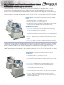
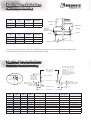
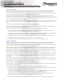
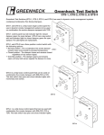
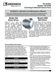
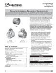
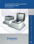
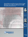
High Wind and Hurricane Zone Fans
Models H-G, H-GB, H-CUE and H-CUBE
Belt and Direct Drive Exhaust Fans
The Hurricane season has brought a new level of attention to wind resistance in the
HVAC Industry. As you know, 2005 ended the worst hurricane season in history. With
this increased level of awareness, comes a greater need for high wind resistant roof
mounted equipment. To prevent water infiltration and building damage, it is critical that
roof top equipment stay affixed to the roof. But how do you know which product can
withstand high winds? Turn to Greenheck Models H-G, H-GB, H-CUE and H-CUBE to
ensure your exhaust fans stay affixed to the roof.
Hurricane winds start at 75 mph. At speeds of 150 mph, wind can exert a 61 pound per
square foot pressure or over 750 pounds of force on a fan and curb. Forceful winds
were the cause of most hurricane damage, exceeding $124 billion dollars in damage in
2005.
•
Greenheck is leading the Hurricane Standards development
•
Models H-G, H-GB, H-CUE and H-CUBE are third-party tested
•
Finite Element Analysis (FEA) done by licensed Professional Engineer
(including P.E. in Florida, Texas, Louisiana…)
•
Full scale wind tunnel tested to 150 MPH
•
Tested as an assembly
•
No tie downs to roof are required
Severe weather calls for serious protection. We have the solution. Greenheck Models
H-G, H-GB, H-CUE and H-CUBE. Remember that these are the only tested and proven
high wind resistant fans. Don’t sacrifice quality and durability–specify the only fans that will
survive hurricane force winds.
November
2006
High Wind and Hurricane Zone Fans
®
Withstands winds up to 150 MPH
The Greenheck Models H-G and H-GB are downblast roof exhaust fans. Applications include general clean air and light
moisture exhaust. The downblast design is ideal for all applications where air is discharged directly onto the roof surface.
Models H-G and H-GB have been specifically designed for high wind and extreme weather applications. Structural bracing on
the interior of the fan, tabbed and riveted curb cap corners, and high strength materials provide the added strength required to
withstand winds of up to 150 MPH. Standard with a 12 inch (305 mm) tall H-GPF curb, no tie downs to the roof are required.
(Other curb options are available.)
Performance: For full performance listings refer to the H-G and H-GB
Catalog.
•
Air performance up to 14,000 CFM (24,000 m3/hr).
•
Pressure range from 0-2.75 inches wg (0-700 Pa).
•
All fan sizes are tested in our AMCA Accredited Laboratory, and all models
are licensed to bear the AMCA sound and air performance seal.
Standard Construction
•
Internal Bracing - High strength internal support structure and bracing.
•
Shroud - Heavy gauge reinforced drawn shroud with integral rolled bead
for consistent material thickness and strength.
•
Drive Assembly - Motor and drive frame are isolated from the airstream and
mounted on true vibration isolators, and sized for 150% of maximum driven
horsepower. (No steel to steel contact)
•
Bearings - Pillow block design selected for a minimum average L10 life in
excess of 100,000 hours (L50 life of 500,000 hours) at maximum cataloged
speed.
•
Disconnect - NEMA-1 disconnect is mounted and wired from the factory.
The Greenheck Models H-CUE and H-CUBE are upblast roof exhaust fans. Applications include restaurant exhaust and mild
contaminants. The upblast design is ideal for all applications where it is important to discharge air away from the roof surface.
Models H-CUE and H-CUBE have been specifically designed for high wind and extreme weather applications. Structural
bracing on the interior and exterior of the fan, tabbed and riveted curb cap corners, and high strength materials provide the
added strength required to withstand winds of up to 150 MPH. Standard with a 12 inch (305 mm) tall H-GPF curb, no tie downs
to the roof are required. (Other curb options are available.)
Performance: For full performance listings refer to the H-CUE and
H-CUBE Catalog.
•
Air performance up to 14,700 CFM (25,000 m3/hr).
•
Pressure range from 0-5 inches wg (0-1,250 Pa).
•
All fan sizes are tested in our AMCA Accredited Laboratory, and all models
are licensed to bear the AMCA sound and air performance seal.
Standard Construction
2
•
Internal Bracing - Additional high strength internal bracing structure.
•
External Bracing - Integral high strength mounted external bracing.
•
Windband - Heavy gauge one piece windband with integral rolled bead,
100% welded to an aluminum curb cap.
•
Drive Assembly - Motor and drive frame are isolated from the airstream
and mounted on true vibration isolators, and sized for 150% of maximum
driven horsepower.
•
Bearings - Bearings are pillow block design selected for a minimum
average L10 life in excess of 100,000 hours (L50 life of 500,000 hours) at
maximum cataloged speed.
•
Disconnect - NEMA-1 disconnect is mounted and wired from the factory.
•
Curb Cap - Heavy gauge with pre-punched mounting holes.
High Wind and Hurricane Zone Fans
®
Third Party Testing and Certifications
The Greenheck high wind models have been thoroughly tested in accordance with recognized standards. With the H-G,
H-GB, H-CUE and the H-CUBE you are not only getting a superior product built by a quality company, you are getting
the assurance through a number of third party certifications that the fan is capable of withstanding high winds.
•
State P.E. Calculations: Models have been
reviewed by state licensed professional
engineers to ensure that they conform to the
requirements of ASCE 7-02 Minimum Design
Loads for Buildings and Other Structures,
International Building Code and the Florida
Building Code.
•
Test Protocols: Models have been subjected
to an extensive testing regime. The models
have been tested in accordance with ASTM
E330 standards at design pressures that
correspond to over 150 MPH wind loads.
•
Computational Fluid Dynamics (CFD):
Greenheck leads the industry with cutting edge
technology. Computational Fluid Dynamics
simulates the airflow of high speed (150 MPH)
winds over the surface of fans. The software
records the force profile that the wind exerts
on the fan, which can be used to complete
Finite Element Analysis of the stresses in each
unit. Models have been completely analyzed
utilizing CFD to prove superior strength and
resistance to high winds.
•
Finite Element Analysis (FEA): Utilizing the
results from CFD analysis Greenheck can
accurately predict the stress, strain, and
deflection that result from high wind loads. A
complete FEA utilizing CFD results is used to
verify the fans capabilities and prove the results
of professional engineer calculations.
When high wind forces are a concern, turn to Greenheck’s high wind models. Models H-G and H-GB downblast
roof exhaust fans and H-CUE and H-CUBE upblast restaurant exhaust fans are the only fans tested and certified to
withstand high winds. Don’t sacrifice quality and durability—specify the only fans that will survive hurricane force winds,
Greenheck models H-G, H-GB, H-CUE and H-CUBE.
3
Typical Installation
®
Fan to Curb Mounting
H-G
Size
H-GB
Size
Fasteners
Per Side
Total
Fasteners
060 - 141
098 - 161
3
12
150 - 180
180 - 300
5
20
Fan to curb tie down is not required to meet 150 MPH wind loads for size 240
and smaller.
H-CUE
Size
H-CUBE
Size
Fasteners
Per Side
Model H-G
or
H-GB
Tie Down is
optional on
sizes 060 - 240
060 - 161
098 - 161
3
12
180 - 240
5
20
-
300
9
36
Fastener
Fastener
Total
Fasteners
180 - 200
Model H-CUE
or
H-CUBE
H-GPF or SD Curb
Fasteners on each side of the fan are to be installed with one fastener 4 inches (102 mm) from each edge and one
fastener centered. The remaining fasteners are to be equally spaced.
Typical Installation
Concrete Deck Anchoring
Use 3/8 inch (10 mm) expansion
anchor or equal into concrete.
Outside of Roof Curb
(1 inch (25 mm) less than
Fan Curb Cap)
1¼ inch (32 mm)
H-GPF Curb Height
8 to 18 inches
(203 to 457 mm)
(Optional 24 inch
(610 mm) SD Curb)
1¼ inch
(32 mm)
Fasteners one on each corner
as detailed.
Each side at center of unit.
Maximum fastener spacing of 8
inches (203 mm), add additional
fasteners to satisfy.
1 inch (25 mm) Insulation
Roof Opening
2½ inch (64 mm)
Embedment Recommended.
Minimum 15/8 inch (41 mm).
Minimum Concrete
Strength of 2000 PSI
Minimum 1¾ inch
(44 mm) edge distance
Corner Detail
5 inch (127 mm) Mounting Flange
Center fasteners
on flange
Outside Flange
4
H-G
Size
H-GB
Size
H-CUE
Size
H-CUBE
Size
Fan Curb Cap
Roof Opening
Fasteners
Per Side
Outside Flange
060 - 075
-
060 - 075
-
17 x 17 (432 x 432)
10½ x 10½ (267 x 267)
5
26 x 26 (660 x 660)
080 - 095
-
-
-
17 x 17 (432 x 432)
12½ x 12½ (318 x 318)
5
26 x 26 (660 x 660)
-
-
080 - 095
-
19 x 19 (483 x 483)
12½ x 12½ (318 x 318)
5
28 x 28 (711 x 711)
101 - 121
071 - 131
098 - 131
098 - 131
19 x 19 (483 x 483)
14½ x 14½ (368 x 368)
5
28 x 28 (711 x 711)
131 - 141
141 - 161
141 - 161
141 - 161
22 x 22 (559 x 559)
18½ x 18½ (470 x 470)
5
31 x 31 (787 x 787)
150
-
-
-
26 x 26 (660 x 660)
18½ x 18½ (470 x 470)
5
35 x 35 (889 x 889)
160 - 180
180 - 200
180 - 200
180 - 200
30 x 30 (762 x 762)
20½ x 20½ (521 x 521)
7
39 x 39 (991 x 991)
-
220 - 240
-
220 - 240
34 x 34 (864 x 864)
26½ x 26½ (673 x 673)
7
43 x 43 (1092 x 1092)
-
260 - 300
-
300
40 x 40 (1016 x 1016)
32½ x 32½ (826 x 826)
7
49 x 49 (1245 x 1245)
All dimensions in inches (millimeters).
Typical Installation
®
Metal Building/Steel Deck Anchoring
Outside of Roof Curb
(1 inch (25 mm) less than
Fan Curb Cap)
H-GPF Curb Height
8 to 18 inches
(203 to 457 mm)
(Optional 24 inch
(610 mm) SD Curb)
1¼ inch (32 mm)
1¼ inch
(32 mm)
1 inch (25 mm) Insulation
Use #12-14 self-drilling
screws or equal.
Fasteners one on each corner
as detailed.
Each side at center of unit.
Maximum fastener spacing
of 8 inches (203 mm), add
additional fasteners to satisfy.
Roof Opening
Corrugated
Roof Deck
Minimum 12 Ga. Steel
Corner Detail
Roof Truss
5 inch (127 mm) Mounting Flange
Outside Flange
H-G
Size
H-GB
Size
H-CUE
Size
H-CUBE
Size
060 - 075
-
060 - 075
-
080 - 095
-
-
-
-
080 - 095
101 - 121
071 - 131
098 - 131
131 - 141
141 - 161
141 - 161
Center fasteners
on flange
Roof Opening
Fasteners
Per Side
17 x 17 (432 x 432)
10½ x 10½ (267 x 267)
5
26 x 26 (660 x 660)
-
17 x 17 (432 x 432)
12½ x 12½ (318 x 318)
5
26 x 26 (660 x 660)
-
19 x 19 (483 x 483)
12½ x 12½ (318 x 318)
5
28 x 28 (711 x 711)
098 - 131
19 x 19 (483 x 483)
14½ x 14½ (368 x 368)
5
28 x 28 (711 x 711)
141 - 161
22 x 22 (559 x 559)
18½ x 18½ (470 x 470)
5
31 x 31 (787 x 787)
Fan Curb Cap
Outside Flange
150
-
-
-
26 x 26 (660 x 660)
18½ x 18½ (470 x 470)
5
35 x 35 (889 x 889)
160 - 180
180 - 200
180 - 200
180 - 200
30 x 30 (762 x 762)
20½ x 20½ (521 x 521)
7
39 x 39 (991 x 991)
-
220 - 240
-
220 - 240
34 x 34 (864 x 864)
26½ x 26½ (673 x 673)
7
43 x 43 (1092 x 1092)
-
260 - 300
-
300
40 x 40 (1016 x 1016)
32½ x 32½ (826 x 826)
7
49 x 49 (1245 x 1245)
All dimensions in inches (millimeters).
Typical Installation
Wood Deck Anchoring
Use #12 Wood Screws or equal into
minimum No. 1/No. 2 Southern Pine
wood support.
Outside of Roof Curb
(1 inch (25 mm) less than
Fan Curb Cap)
1¼ inch (32 mm)
Each side at center of unit. Maximum
fastener spacing of 6 inches (152 mm),
add additional fasteners to satisfy.
1 inch (25 mm) Insulation
H-GPF Curb Height
8 to 18 inches
(203 to 457 mm)
(Optional 24 inch
(610 mm) SD Curb)
1¼ inch
(32 mm)
Fasteners one on each corner
as detailed.
Roof Opening
2 inch (51 mm)
Minimum Embedment
Wood Decking
Corner Detail
5 inch (127 mm) Mounting Flange
Center fasteners
on flange
Wood Support Member
Nominal 2 x 4, 6, 8
Outside Flange
H-G
Size
H-GB
Size
H-CUE
Size
H-CUBE
Size
Fan Curb Cap
Roof Opening
Fasteners
Per Side
Outside Flange
060 - 075
-
060 - 075
-
17 x 17 (432 x 432)
10½ x 10½ (267 x 267)
5
26 x 26 (660 x 660)
080 - 095
-
-
-
17 x 17 (432 x 432)
12½ x 12½ (318 x 318)
5
26 x 26 (660 x 660)
-
-
080 - 095
-
19 x 19 (483 x 483)
12½ x 12½ (318 x 318)
5
28 x 28 (711 x 711)
101 - 121
071 - 131
098 - 131
098 - 131
19 x 19 (483 x 483)
14½ x 14½ (368 x 368)
5
28 x 28 (711 x 711)
131 - 141
141 - 161
141 - 161
141 - 161
22 x 22 (559 x 559)
18½ x 18½ (470 x 470)
5
31 x 31 (787 x 787)
150
-
-
-
26 x 26 (660 x 660)
18½ x 18½ (470 x 470)
7
35 x 35 (889 x 889)
160 - 180
180 - 200
180 - 200
180 - 200
30 x 30 (762 x 762)
20½ x 20½ (521 x 521)
7
39 x 39 (991 x 991)
-
220 - 240
-
220 - 240
34 x 34 (864 x 864)
26½ x 26½ (673 x 673)
7
43 x 43 (1092 x 1092)
-
260 - 300
-
300
40 x 40 (1016 x 1016)
32½ x 32½ (826 x 826)
9
49 x 49 (1245 x 1245)
All dimensions in inches (millimeters).
5
Specifications
®
Centrifugal Downblast Roof Exhaust Fans
H-G — Direct Drive
Model H-G spun aluminum exhaust fans shall be centrifugal direct driven type. The fan wheel shall be centrifugal backward
inclined, constructed of aluminum and shall include a wheel cone carefully matched to the inlet cone for precise running
tolerances. Wheels shall be statically and dynamically balanced. The fan housing shall be drawn from high strength aluminum and
connected to a heavy gauge steel internal frame with integral bracing and a birdscreen.
Motors shall be heavy duty ball bearing type, carefully matched to the fan load, and furnished mounted to the steel drive
assembly at the specified voltage, phase, and enclosure. Motors or drive assembly shall be mounted on vibration isolators. Fresh
air for motor cooling shall be drawn into the motor compartment through a large space between the fan shroud and motor cover.
Motors shall be readily accessible for maintenance.
A disconnect shall be NEMA rated and factory installed with wiring included from the fan motor to a junction box installed within
the motor compartment. A conduit chase shall be provided through the base to the motor compartment for ease of electrical
wiring.
All fans shall bear the AMCA Certified Ratings Seal for sound and air performance.
Each fan shall bear a permanently affixed manufacturer’s engraved nameplate constructed of aluminum and containing the model
number and individual serial number for future identification.
Fans shall meet all Greenheck wind load standards and shall contain the following third party certifications.
•
Licensed P.E. calculations shall be available for fan per ASCE 7-02 Minimum Design Loads for Buildings and Other
Structures for exposure class C, 60 foot building height, and a type II building.
•
Fan shall be tested in accordance with ASTM E330-02. Structural Performance of Exterior Windows, Doors, Skylights, and
Curtain Walls by Uniform Static Air Pressure Difference at the ASCE 7-02 calculated design load.
•
Licensed P.E. calculations for attachment of fan to curb shall be available for ASCE 7-02 determined design pressure.
•
All calculations and testing shall be done by a state licensed P.E., and a certified test lab.
Fans shall be Greenheck model H-G manufactured by Greenheck Fan Corporation in Schofield Wisconsin.
H-GB — Belt Drive
Model H-GB spun aluminum exhaust fans shall be centrifugal belt driven type. The fan wheel shall be centrifugal backward
inclined, constructed of aluminum and shall include a wheel cone carefully matched to the inlet cone for precise running
tolerances. Wheels shall be statically and dynamically balanced. The fan housing shall be drawn from high strength aluminum and
connected to a heavy gauge steel internal frame with integral bracing and a birdscreen.
Motors shall be heavy-duty ball bearing type, carefully matched to the fan load, and furnished mounted to the steel drive frame
at the specified voltage, phase, and enclosure. Drive frame assembly shall be constructed of heavy gauge steel with engineered
forms for added strength. Motors and drives shall be mounted on vibration isolators with no metal to metal contact, out of the
airstream. Fresh air for motor cooling shall be drawn into the motor compartment through a large space between the fan shroud
and the motor cover. Motors and drives shall be readily accessible for maintenance.
Precision ground and polished fan shafts shall be mounted in pillow block ball bearings. Bearings shall be selected for a minimum
(L10) life in excess of 100,000 hours (L50 average of 500,000 hrs) at maximum cataloged operating speed. Drives shall be sized
for a minimum of 150% of driven horsepower. Pulleys shall be of the cast type, keyed and securely attached to the wheel and
motor shafts.
Motor pulleys shall be adjustable for final system balancing. A disconnect switch shall be NEMA rated and factory installed with
wiring included from the fan motor to a junction box installed within the motor compartment. A conduit chase shall be provided
through the base to the motor compartment for ease of electrical wiring.
All fans shall bear the AMCA Certified Ratings Seal for sound and air performance.
Each fan shall bear a permanently affixed manufacturer’s engraved metal nameplate containing the model number and individual
serial number for future identification.
Fans shall meet all Greenheck wind load standards and shall contain the following third party certifications.
•
Licensed P.E. calculations shall be available for fan per ASCE 7-02 Minimum Design Loads for Buildings and Other Structures
for exposure class C, 60 foot building height, and a type II building.
•
Fan shall be tested in accordance with ASTM E330-02. Structural Performance of Exterior Windows, Doors, Skylights and
Curtain Walls by Uniform Static Air Pressure Difference at the ASCE 7-02 calculated design pressure.
•
Licensed P.E. calculations for attachment of fan to curb shall be available for ASCE 7-02 determined design pressure.
•
All calculations and testing shall be done by a state licensed P.E., and a certified test lab.
Fans shall be Greenheck models H-GB and H-GB-HP, manufactured by Greenheck Fan Corporation in Schofield, Wisconsin.
6
Specifications
®
Centrifugal Upblast Roof Exhaust Fans
H-CUE — Direct Drive
Model H-CUE spun aluminum exhaust fans shall be centrifugal direct driven type. The fan wheel shall be backward inclined,
constructed of aluminum and shall include a wheel cone carefully matched to the inlet venturi for precise running tolerances.
Wheels shall be statically and dynamically balanced. The fan housing shall be uniquely spun from a cylinder of heavy gauge
aluminum and mounted to a high strength steel frame. The windband shall be one piece and 100% continuously robotically
welded to the one piece aluminum curb cap. High wind load braces shall connect the curb cap to the windband.
Motors shall be heavy duty ball bearing type, carefully matched to the fan load, and furnished mounted to the steel drive
assembly at the specified voltage, phase, and enclosure. Motors or drive assembly shall be mounted on vibration isolators. Fresh
air for motor cooling shall be drawn into the motor compartment through a breather tube free of discharge contaminants. Motors
shall be readily accessible for maintenance.
A disconnect shall be NEMA rated and factory installed with wiring included from the fan motor to a junction box installed within
the motor compartment. A conduit chase shall be provided through the base to the motor compartment for ease of electrical
wiring.
All fans shall bear the AMCA Certified Ratings Seal for sound and air performance.
Each fan shall bear a permanently affixed manufacturer’s engraved nameplate constructed of aluminum and containing the model
number and individual serial number for future identification.
Fans shall meet all Greenheck wind load standards and shall contain the following third party certifications:
•
Licensed P.E. calculations shall be available for fan per ASCE 7-02 Minimum Design Loads for Buildings and Other
Structures for exposure class C, 60 foot building height, and a type II building.
•
Fan shall be tested in accordance with ASTM E330-02. Structural Performance of Exterior Windows, Doors, Skylights, and
Curtain Walls by Uniform Static Air Pressure Difference at the ASCE 7-02 calculated design load.
•
Licensed P.E. calculations for attachment of fan to curb shall be available for ASCE 7-02 determined design pressure.
•
All calculations and testing shall be done by a state licensed P.E., and a certified test lab.
Fans shall be Greenheck models H-CUE or H-CUE-HP manufactured by Greenheck Fan Corporation in Schofield, Wisconsin.
H-CUBE — Belt Drive
Model H-CUBE spun aluminum exhaust fans shall be centrifugal belt driven type. The fan wheel shall be centrifugal backward
inclined, constructed of aluminum and shall include a wheel cone carefully matched to the inlet cone for precise running
tolerances. Wheels shall be statically and dynamically balanced. The fan housing shall be uniquely spun from a cylinder of heavy
gauge aluminum and mounted to a high strength steel frame. The windband shall be 100% continuously robotically welded to the
one-piece aluminum curb cap. High wind load braces shall connect the curb cap to the windband.
Motors shall be heavy-duty ball bearing type, carefully matched to the fan load, and furnished mounted to the steel drive frame
at the specified voltage, phase, and enclosure. Drive frame assembly shall be constructed of heavy gauge steel with engineered
forms for added strength. Motors and drives shall be mounted on vibration isolators with no metal to metal contact, out of the
airstream. Fresh air for motor cooling shall be drawn into the motor compartment through a ten square inch breather tube free of
discharge contaminants. Motors and drives shall be readily accessible for maintenance.
Precision ground and polished fan shafts shall be mounted in pillow block ball bearings. Bearings shall be selected for a minimum
(L10) life in excess of 100,000 hours (L50 average of 500,000 hrs) at maximum cataloged operating speed. Drives shall be sized
for a minimum of 150% of driven horsepower. Pulleys shall be of the cast type, keyed and securely attached to the wheel and
motor shafts.
Motor pulleys shall be adjustable for final system balancing. A disconnect switch shall be NEMA rated and factory installed with
wiring included from the fan motor to a junction box installed within the motor compartment. A conduit chase shall be provided
through the base to the motor compartment for ease of electrical wiring.
All fans shall bear the AMCA Certified Ratings Seal for sound and air performance.
Each fan shall bear a permanently affixed manufacturer’s engraved metal nameplate containing the model number and individual
serial number for future identification.
Fans shall meet all Greenheck wind load standards and shall contain the following third party certifications.
•
Licensed P.E. calculations shall be available for fan per ASCE 7-02 Minimum Design Loads for Buildings and Other Structures
for exposure class C, 60 foot building height, and a type II building.
•
Fan shall be tested in accordance with ASTM E330-02. Structural Performance of Exterior Windows, Doors, Skylights and
Curtain Walls by Uniform Static Pressure Difference, at the ASCE 7-02 calculated design pressure.
•
Licensed P.E. calculations for attachment of fan to curb shall be available for ASCE 7-02 determined design pressure.
•
All calculations and testing shall be done by a state licensed P.E., and a certified test lab.
Fans shall be Greenheck models H-CUBE, H-CUBE-HP and H-CUBE-XP manufactured by Greenheck Fan Corporation in
Schofield, Wisconsin.
7
Severe Duty Products
Model USGF is a leader in severe wind and severe grease
applications. The USGF has been subjected to Miami-Dade
test protocols TAS-201/202/203 for wind pressure and missile
impact. After extensive testing exceeding all standards the
USGF was still in operating condition. The USGF is UL/cUL
listed for restaurant exhaust with continuous operation at
400ºF. The unit is constructed entirely of steel and includes a
non-stick coated steel wheel, NEMA-3R disconnect, hinged
base assembly, and clean out port. Making the USGF ideal in
high wind applications. Performance is AMCA certified to
7,000 cfm and up to 3 inches wg.
Models LDP/LBP are the only rooftop exhaust fan that can withstand
design pressures in excess of 140 PSF. The LDP/LBP with SDLE
enclosure passes all Miami-Dade and Florida Building Code requirements
(TAS-201/202/203). The severe duty LDP/LBP is constructed of MiamiDade approved louvers (model ESD-603D) with a high strength structural
steel support frame, and ships mounted to a 12 gauge steel curb. For
applications requiring missile impact resistance turn to the Greenheck
severe duty LDP/LBP for all your exhausting needs. Performance on
these units is AMCA certified and ranges from 100 up to 14,200 cfm and
up to 1.25 inches wg.
Model RSFP is the only rooftop centrifugal supply fan that can
withstand design pressures in excess of 140 PSF. The RSFP
with SDLE enclosure passes all Miami-Dade and Florida Building
Code requirements (TAS-201/202/203). The severe duty RSFP is
constructed of Miami-Dade approved louvers (model ESD-603D) with
a high strength structural steel support frame, and ships mounted
to a 12 gauge steel curb. For untempered supply applications with
missile impact resistance turn to the Greenheck severe duty RSFP.
Performance on these units is AMCA certified and ranges from 650
up to 14,300 cfm and up to 2 inches wg.
The Severe Duty Louver line is the most diverse in the industry. We were
first to offer a Miami-Dade qualified Severe Duty Louvered Enclosure (model
SDLE) and offer three Miami-Dade qualified louver models as well. With the
ability to complete Large Missile Impact and Wind-Driven Rain Testing inhouse, we continue to accelerate our product development and remain an
industry leader.
The Vektor product line is used in applications requiring dilution of exhaust air
or high plume rise above the roof line. Common applications include laboratory
exhaust, odor control and kitchen exhaust. Vektor models are AMCA certified and
UL/cUL listed. Fan systems are rated to withstand 125 MPH wind loading without
the use of guy wires. Vektor product line meets NFPA, ANSI Z9.7, and ASHRAE
code requirements and guidelines for laboratory exhaust systems.
Whether your application calls for meeting
a high wind load, impact resistance, or
resistance to the penetration of wind-driven
rain, Greenheck has the solution.
P.O. Box 410 • Schofield, WI 54476-0410 • Phone (715) 359-6171 • greenheck.com
Promo High Wind & Hurricane Fans RG
Rev. 2 November 2006
Copyright © 2006 Greenheck