1
service Manual for
Basic American’s Matrix 709 series
InstructIons For use
etL/uL/csA Approved
uL 60601-1
Iec 60601-2-38
csA 22.2 601.1
Basic American Medical products is a division of GF Health products, Inc.
999-0807-190 • rev d • 2011
Basic American Medical Products
336 Trowbridge Drive
Fond du Lac, WI 54937
www.basicamerican.com
For Matrix II Bed Service Parts please contact our
Customer Service Department at
1-800-365-2338
GF Health Products, Inc.
2935A Northwest Parkway
Atlanta, GA 30360
www.grahamfield.com
To order a Matrix II Bed please contact a
Graham Field Sales Representative at
1-800-554-9215
This service manual covers the following Matrix II Models:
Full-electric with standard caster carriage: 76” Grid = Mp7074; 80” Grid = Mp7174; 76” pan = Mp7014; 80” pan = Mp7114
Full-electric with M-Lok caster carriage: 76” Grid = MM7074; 80” Grid = MM7174; 76” pan = MM7014; 80” pan = MM7114
Full-electric with total Lock caster carriage: 76” Grid = Mp707404; 80” Grid = Mp717404; 76” pan = Mp701404; 80” pan = Mp711404
Important notIce
The information contained in this document is subject to change without notice.
Please check all parts for shipping damage and test before using.
In case of damage, DO NOT USE.
Copyright 2011 Basic American Medical Products
T ABLE OF CONTENTS
safety information and specifications
safety & warning information . . . . . . . . . . . . . . . . . . . . . . . 1
entrapment compliance information . . . . . . . . . . . . . . . . 2
bed features & specifications . . . . . . . . . . . . . . . . . . . . . . . . . 3
• Features & Mechanical Dimensions
• Electrical Specifications
• Available Options/Accessories
bed positioning specifications . . . . . . . . . . . . . . . . . . . . . . . . 4
• Maximum High and Low Bed Positions
• Maximum Head/Back Elevation/Angle
• Maximum Knee/Foot Elevation/Angle
operating your bed
operation - std. pendant/hand controller . . . . . . . . . . 5
• Pendant Diagram and Operational Instructions
operation - opt. staff/nurse control . . . . . . . . . . . . . . . . . 6
• Staff Diagram and Operational Instructions
board assembly & Misc. features
standard head- & footboards . . . . . . . . . . . . . . . . . . . . 7 - 10
• Std. Head- & Footboard Boring Patterns
• Assembly Instructions
• Head- & Footboard Assembly Parts
• Head- & Footboard Assembly Diagram
optional embedded staff control . . . . . . . . . . . . . . . . . . . . 11
• Assembly Instructions
• Footboard Embedded Control Parts & Diagram—single control box
standard & optional wallsavers . . . . . . . . . . . . . . . . . . . . . 13
• Assembly Instructions
• Standard Wallsaver & Side Wallsaver Assembly Parts
• Wallsaver Assembly Diagrams
Foot rail bracket assembly . . . . . . . . . . . . . . . . . . . . . . . . . . 19
• Diagram, Parts, and Assembly Instructions
Head & foot assist bars/rails . . . . . . . . . . . . . . . . . . . . 20 & 21
• Diagram, Parts, and Assembly Instructions
standard 4” extension pan . . . . . . . . . . . . . . . . . . . . . . . . . . 22
• Diagram, Parts, and Assembly Instructions
optional 42” wide deck & Wide deck ext. pan . . . 23 & 24
• Diagram, Parts, and Assembly Instructions
trapeze support . . . . . . . . . . . . . . . . . . . . . . . . . . . . . . . . . . . . . . 25
• Diagram, Parts, and Assembly Instructions
bed parts and hardware
Head, Knee & foot decks to main frame . . . . . . . . . . . . . 27
• Diagram, Parts, and Assembly Instructions
main frame to u-levers AND DRAG LINK . . . . . . . . . . . . . . 28
• Diagram, Parts, and Assembly Instructions
LOWER u-levers to standard caster carriage . . . . . . . 29
• Diagram, Parts, and Assembly Instructions
LOWER u-levers to lock caster carriage w/m-lok . . . 30
• Diagram, Parts, and Assembly Instructions
electronics & cabling
head motor to head deck and main frame . . . . . . . . . 32
• Diagram, Parts, and Assembly Instructions
foot motor to knee deck and main frame . . . . . . . . . . 33
• Diagram, Parts, and Assembly Instructions
hi/lo motorS to drag linkS and u-leverS . . . . . . . . . . . . 34
• Diagram, Parts, and Assembly Instructions
control box connections & cabling . . . . . . . . . . . . . . . . 36
• Diagram, Parts, and Connection Instructions
Head, Foot, and Hi/Lo cable routing . . . . . . . . . . . . . 37 - 39
• Diagram and Routing Instructions
standard mattress retainers . . . . . . . . . . . . . . . . . . . . . . . . 14
• Assembly Instructions
• Mattress Retainer Assembly Parts & Diagram
pendant cable & power cord routing . . . . . . . . . . 40 & 41
• Diagram and Routing Instructions
OPTIONAL edema foot ratchet . . . . . . . . . . . . . . . . . . . . . . . . 15
• Edema Diagram and Operational Instructions
miscellaneous
accessories assembly
recommended service and maintenance . . . . . . . . . . . . . 43
Head & foot half-rails . . . . . . . . . . . . . . . . . . . . . . . . . . . 17 & 18
• Diagram, Parts, and Assembly Instructions
notes . . . . . . . . . . . . . . . . . . . . . . . . . . . . . . . . . . . . . . . . . . . . . . . . . 44
electronic troubleshooting . . . . . . . . . . . . . . . . . . . . . . . . 42
Basic American Medical products, a division of GF Health products, Inc.
S
AFETY & WARNING INFORMATION - please read before operation
This product is a variable height, adjustable mattress platform, which will provide comfort and convenience for residents/patients and caregivers in long term care settings.
All Warning/Caution labels attached to the bed apply to any hazards or unsafe practices that could result in personal injury and/or property damage. DO NOT remove
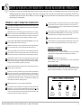
any Warning/Caution labels attached to the bed. Whenever you see this symbol ! please pay special attention to the warning instructions and comments for your safety
and the safety of the resident/patient.
IMPORTANT Safety Operating Information
!
!
The MAXIMUM SAFE WORKING LOAD for the Matrix II Bed, including the mattress, panels,
side rails, and accessories, taking into consideration proper positioning, patient size, realignment,
transfer, and overall care, is 450 lbs.
MAKE SURE all electrical cords DO NOT get tangled around the bed, side rails, or legs during
transport or normal operation of the bed. NEVER operate the bed if a Power Cord or Plug is
damaged or not working properly. Contact qualified Service Personnel for examination and
repair. ALWAYS unplug the Power Cord when performing any maintenance on the bed.
!
The bed’s Pendant Cord MUST BE ROUTED AND SECURED PROPERLY to ensure it does
not become entangled and eventually severed during use.
!
MAKE SURE all locking casters and/or locking mechanisms are properly engaged when the
bed is not in transport in order to avoid any rolling movement when the bed is at rest.
!
When operating the High/Low, Knee, or Back Functions of the bed, ALWAYS ensure that the
confined individual is positioned properly within the confines of the bed. DO NOT let any
extremities protrude over the side or between the bed rails when performing these functions.
!
The head/back deck is designed to remain in its full upright angled position when accessing
the frame for cleaning. This is also a safety feature for when the bed is powered down. ALWAYS
make sure the deck is fully engaged in the upright position when lifting or lowering it manually.
Not doing so could result in damage to property or personal injury.
!
DO NOT lower the bed when objects are beneath it. Failure to inspect under the bed can result
in damage to property or personal injury.
!
DO NOT use the side rails as push handles for moving the bed. Side rails can be deformed or
broken if excessive side pressure is exerted. The purpose of the rails is to define the edge of
the sleeping surface. They are not meant for patients considered as high risks for entrapment
(i.e. patients with pre-existing conditions such as confusion, restlessness, lack of muscle control,
altered mental status, either organic or medicinal, or a combination thereof). Additional safety
measures should be considered for such high-risk patients.
!
!
!
DO NOT open assemblies such as the Actuators, Hand Control, or Control Box. If unauthorized
personnel perform work on these components, the manufacturer’s warranty becomes void.
DO NOT use unauthorized parts, accessories, or adapters other than those specified/authorized
by Graham-Field Health Products.
!
When using nasal- or masked-type administering equipment, all oxygen or air tubing MUST
BE ROUTED AND SECURED PROPERLY to ensure that the tubing does not become
entangled and eventually severed during the normal operation of the bed.
!
!
Keep all moving parts free of obstructions (i.e. blankets/ sheets, heating blankets/pads, wiring, etc.)
The bed is intended for use, storage, and transport within a temperature range of -40˚C to +60˚C.
It has a water-resistance rating of IPX4 and IS NOT to be power-washed or submersed.
Operating Conditions
Operation of the bed is based on the following conditions:
Ambient Temperature of +10˚C to +40˚C; Relative Humidity of 30% to 75% (Non-condensing);
Atmospheric Pressure of 700hPa to 1060hPa; and a Splash Protection of IEC 60529.
Storage
Storage of the bed is based on the following conditions:
Ambient Temperature of -10˚C to 70˚C; Relative Humidity of 10% to 100%; and an Atmospheric
Pressure of 500hPa to 1060hPa.
Radio Frequency Interference (RFI)
RFI influences most electronic equipment. Caution should be exercised with regard to the use
of portable communications equipment in the area around such equipment. If RFI causes erratic
behavior, shut the bed off immediately. Leave it off while the transmission is in progress.
label symbol definitions
NEVER permit more than one (1) person on/in the bed AT ANY TIME.
Body weight should be evenly distributed over the sleeping surface of the bed. DO NOT allow
the patient to lay, sit, or lean in such a way that their entire body weight is placed only on the
raised head or foot sections of the bed. This especially applies when repositioning or transferring
a patient in or out of the bed. Increased risk may occur when the patient’s size and/or weight
are inappropriate for the bed’s dimensions or weight capacity.
Basic American Medical products, a division of GF Health products, Inc. • Matrix II • rev d Manual
!
!
consult
Accompanying
documents
safe
Working
Load
protected
Grounded
device
type B
equipment &
Applied parts
p1
E
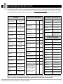
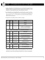
ntrapment compliance information
On March 10, 2006, the FDA (U.S. Food and Drug Administration) released long-awaited guidelines for reducing the risk of bed entrapment: “Hospital Bed System
Dimensional and Assessment Guidance to Reduce Entrapment”. The new Guidance identifies potential entrapment areas and those body parts most at risk for entrapment; provides design criteria for manufacturers of new hospital/convalescent beds; recommends particular test methods to assess the conformance of existing
hospital/convalescent bed systems; and answers frequently-asked questions about entrapment issues.
The new Guidance was a result of a long-standing collaboration between the FDA and the Hospital Bed Safety Workgroup (HBSW), formed in 1999. Graham-Field’s
Long-Term Care Bed division: Basic American Medical Products, is an HBSW charter member. As a result of Graham-Field’s commitment to product safety, all of
Graham-Field current long-term care beds have been strictly tested and conform to the new FDA Guidance.
The guidelines set forth by the FDA Guidance layout specific dimensional limitations on potentially injury-threatening gaps and spaces that can occur between bed system
components, such as rails, when not properly installed. Graham-Field and Basic American Medical Products have conformed to these guidelines from a manufacturing
aspect. However, entrapment issues can often arise when a healthcare provider/facility has not correctly assembled the components on a bed. It is essential that the provider/
facility fully understand their responsibility in complying to the guidelines set forth by the FDA in order to avoid injury. To that end, we have provided the links below
as a resource for understanding and following these guidelines for the safety of the patient/resident.
Graham-Field encourages all hospital bed owners to read the FDA guidance.
◗ Please visit the FDA’s Hospital Bed Safety page at "http://www.fda.gov/cdrh/beds/"
◗ To find many resources, including a link to the new Guidance page go to "http://www.fda.gov/cdrh/beds/guidance/1537.pdf"
◗ Ordering instructions for a Testing Kit which you can use to determine whether your beds are in conformance with the guidance can be found at
"http://www.fda.gov/cdrh/beds/entrapmentkit.html"("http://www.fda.gov/cdrh/beds/entrapmentkit.html" http://www.fda.gov/cdrh/beds/entrapmentkit.html) ;
◗ A discussion of Clinical Guidance protocol which you can use to assess an individual patient’s needs when using a side rail can be found at
"http://www.ute.kendal.org/learning/documents/clinicalguidance_SideRails.pdf"
These resources will supply you with the knowledge to evaluate the safety of the hospital beds you currently own.
It is also essential to have the correct bed components/accessories that correspond with the needs of your patient/resident and the particular bed you have purchased.
Matching the correct bed component that correlates with the regulatory guidelines can be a daunting task. Our Graham-Field Sales team and the friendly Customer Service
Representatives at Basic American Medical Products can help you sift through the wide array of compliance and bed options. We will help you determine which bed/bed
part is best for your patient’s/resident’s particular needs and help you with your compliance issues.
Basic American Medical products, a division of GF Health products, Inc. • Matrix II • rev d Manual
p2
B
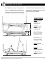
ED features & SPECIFICATIONS
The Matrix II Full-Electric Bed Series offers some outstanding standard and optional features all geared for safety and comfort. We have included both mechanical and
electrical specifications below for your records. *We are excited to introduce a new Anti-Microbial Powder Coat Painting process which has been proven to inhibit the
growth of damaging and disease causing microbes (bacteria, mold, fungus, algae, etc.) on the surface of coated items. Recorded result-reduction of bacteria has been 99.9%.
Features
Sleep Surface Availability
Sleep Surface Options
Sleep Surface Material
Mechanical Dimensions
Welded Tubular
Main Frame Material
Steel (Rectangular
& Square Tubing)
Lock and/or Roll
at any height
Baseboard Wallsaver
Wire - Standard
Mattress Retainers
Two std. on foot deck
Hand Pendant
6-function with long
coil cord
Motors & Control Box
Heavy Duty Casters
*Anti-Microbial Powder Coat
Paint Finish
Entrapment
80”
Overall Bed Length
(with standard wallsaver)
82.00”
86.00”
Overall Bed Width
(with standard rails)
39.75”
39.75”
Overall Bed Width
(with standard boards-no rails)
36.00”
36.00”
Sleep Deck Surface Length
75.00”
79.00”
Sleep Deck Surface Width
35.00”
35.00”
Standard
Quiet DC Electronics
Four Standard
Soft Pantone Grey
FDA Compliant
120 Volt/60 Hz
Current Actuator Rating
LA27
Overall Movement Draw
4 Amps
Classification
8.90” to 25.00”
Standard Locking System
Pendant Holster
76”
11 GA. Hot Rolled Steel
Base Frame Material
Travel Range
Power/Frequency
76” & 80”
Steel Welded Wire Grid (std)
or Pan
electrical specifications
Mode of Operations
10% Max. Duty Cycle
2 minutes on/18 minutes off
Electrical Cord
Type SJT 3/18AWG
Grounded w Hospital Plug
options/accessories
One Step Locking
Mechanism
Std. 4” Pan Extension Kit
Sleep Deck Surface Height
(high position)
25.00”
25.00”
Sleep Deck Surface Height
(low position)
8.90”
8.90”
Under Bed Minimum Clearance
(high position)
5.25”
5.25”
Maximum Head Deck Angle
70º
70º
Maximum Knee Deck Angle
30º
30º
Maximum Knee to Leg Angle
45º
45º
450 lbs.
450 lbs.
Class I, Type B
Foot end/360º roll
Foot end - adds 4” to length
Staff/Nurse Control
Embedded in Footboard
Lockout
Economy or Single
Tubular Wallsaver
Steel
Side Rails
LH and RH/Head or Foot
Assist Bar
LH or RH/Head or Foot
Edema Foot Ratchet
Maximum Safe Working Load
(including mattress, panels, side
rails and accessories, and taking
into consideration patient size,
proper positioning, realignment,
transfer, and overall care.
Foot end
Trapeze
Support & Bar
Traction
Adapter & IV Socket
Battery Backup
Charger, Cable & Battery
Standard Pan Deck
Pan Head, Knee & Foot
42” Wide Deck Kit
Two RH & two LH Sections
Wide 4” Pan Extension Kit
Foot end - adds 4” to length
NOTE: When ordering parts or contacting our customer service department, please have the bed’s model and serial number available.
These can be found on the identification labels which are usually located on the bed frame under the sleep deck.
Basic American Medical products, a division of GF Health products, Inc. • Matrix II • rev d Manual
p3
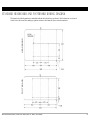
P
ositioning Specifications
The Matrix II Bed Series has infinite positions that serve to help the patient
be more comfortable and gives the practitioner easy access during procedures,
transfers, etc. The correct placement of the bed is essential for the patient’s safety.
The recommended maximum distance for the head function is 70˚. In the event
of a power outage, it is preferred that the knee and back sections be lowered using
an emergency battery pack. If unavailable, the sections can be set into the flat
position by easily removing the actuator mounting pins.
The bed should always be set to its lowest position when the patient is left unattended.
The head and knee functions allow the resident/patient to raise their head or legs.
QUICK REFERENCE:
MAXIMUM (High Position)
Bed height from floor to
sleep deck top = 25.00”
25.00”
8.90”
MINIMUM (Low Position)
Bed height from floor to
sleep deck top = 8.90”
DISTANCE TO WALL (High)
Headboard mounting tube to
end of std. wallsaver = 1.75”
Floor
DISTANCE TO WALL (Low)
Headboard mounting tube to
end of std. wallsaver = 1.50”
MAXIMUM (Head Angle)
Head deck to sleep surface = 70º
MINIMUM (Knee Angle)
Knee deck to sleep surface = 30º
MAXIMUM (Knee/Foot Angle)
Knee deck to foot deck = 45º
Basic American Medical products, a division of GF Health products, Inc. • Matrix II • rev d Manual
p4
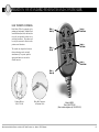
O PERATION OF STANDARD PENDANT/HAND CONTROLLER
Easy Patient Controls
Raise =
Head Up
Each Matrix II Bed is equipped with a
pendant-type hand control—standard. Each
control function (head, bed, and knee) has
two easily recognizable switches for up
and down movement. The pendant can
be easily disconnected to deactivate the
patient control functions.
Raise =
Bed Up
The controls are designed so that more
than one function can be activated
simultaneously. To operate, push the
appropriate buttons to activate the
desired function.
Lower =
Head Down
Lower =
Bed Down
Lower =
Knees Down
Raise =
Knees Up
Pendant Holster
999-0791-000
Male End Connector
of Pendant Cable
Basic American Medical products, a division of GF Health products, Inc. • Matrix II • rev d Manual
Model # HB00
part # 999-0775-305
(Also includes alligator clip 100-0510-001)
p5
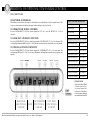
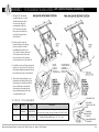
O PERATION OF OPTIONAL STAFF/NURSE CONTROL
part # 999-0775-901
Staff/nurse Controller
The staff/nurse control allows the caregiver to individually lock out all functions of only the pendant control. The
caregiver can also operate the bed from this panel without walking to the side of the bed.
STAFF CONTROL REFERENCE
Head LED Light
Item 10
To Operate the Travel Controls
Foot LED Light
Item 11
Press the “HOLD SELECT” (#13) first, then the appropriate “UP” (#4, 6, or 8) OR “DOWN” (#5, 7, or 9) on
the panel.
Hi/Lo LED Light
Item 12
Hold & Select Button
Item 13
To Lock Out a Pendant Function
Press the “HOLD SELECT” (#13) first, then the appropriate “NO PENDANT” (#1, 2, or 3) on the panel. The
corresponding illuminated LED light (#10, 11 &12) indicates that the function is now locked out on the pendant.
TO OPERATE BED FROM STAFF CONTROL
Raise Head/Back Deck
Push 13 then 4
To Unlock a Pendant Function
Lower Head/Back Deck
Push 13 then 5
Press the “HOLD SELECT” (#13) first, then the appropriate "NO PENDANT" (#1, 2, or 3) on the panel. The
corresponding LED light (#10, 11 & 12) is no longer illuminated, indicating that the pendant can now operate that
function.
Raise Knee/Foot Decks
Push 13 then 6
Lower Knee/Foot Decks
Push 13 then 7
Raise Entire Bed (Hi/Lo)
Push 13 then 8
Lower Entire Bed (Hi/Lo)
Push 13 then 9
Lockout
Led LIGHt
Lockout
Led LIGHt
Lockout
Led LIGHt
TO LOCK OUT HAND CONTROL FUNCTION
Lock Out Head Function
Push 13 then 1
Lock Out Foot Function
Push 13 then 2
Lock Out Hi/Lo Function
Push 13 then 3
PLEASE NOTE:
When the Pendant Hand
Controller is locked out,
you can still operate the
bed from the Staff/Nurse
Control without unlocking
the pendant hand controller.
Head deck
functions &
lockout
hold
HI/LO (raise bed)
functions &
lockout
Basic American Medical products, a division of GF Health products, Inc. • Matrix II • rev d Manual
foot deck
functions &
lockout
p6
HEAD- & FOOTBOARDS
Basic American Medical products, a division of GF Health products, Inc. • Matrix II • rev d Manual
p7
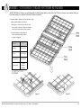
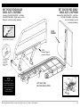
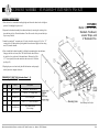
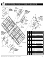
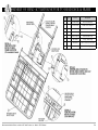
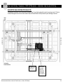
Standard Headboard and Footboard BORING DIAGRAM
FootBoArd
HeAdBoArd
The diagrams below outline the manufacturer’s standardized headboard and footboard boring specifications. All of the dimensions are referenced
from the center and bottom. Before making any significant variations to these dimensions, please contact the manufacturer.
Basic American Medical products, a division of GF Health products, Inc. • Matrix II • rev d Manual
p8
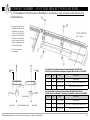
A ssembly - standard head and foot boards
1. Assemble two Mounting Tubes (#4) to the Headboard (#1) and two to the Footboard (#2) using eight 1/4-20 x 4mm
JCB-B Hex Drive Bolts (#6), going through the pre-drilled holes on the boards and into the eight 1/4-20 x .60” Long
Threaded Inserts (#3) (already attached to the boards) as shown. Hand tighten only at this time.
2. Insert the Mounting Tubes into the Main Bed Frame Tubes so that the holes match up as shown. Secure with four
5/16 x 1-1/2” Clevis Pins (#7) and 1-9/16 Hair Pin Clips (#8) (1 each per bed frame tube). The mounting tubes will
slide underneath the two 5/16-18 x 1.50” Carriage bolts that were pre-inserted into the Main Frame Rails at the
head-end of the bed by the manufacturer.
3. Now tighten all screws with a phillips screwdriver. Be careful not to overtighten.
Item #
Quantity
Part #
Description
1
1
-
Headboard*
2
1
-
Footboard*
3
8
100-7025-004
1/4-20 UNC x .60” Long Threaded Insert
(pre-inserted into footboard and headboard)
Headboard & Footboard Mounting Kit (999-0775-000) includes the following parts:
4
4
999-0746-035G
Mounting Tubes
5
4
100-4700-015
1” x 1” Square Tube End Cap (pre-inserted in tubes)
6
8
100-5425-094
1/4-20 x 4mm JCB-B Hex Drive Bolt
7
4
100-7931-007
Clevis Pin - 5/16 x 1-1/2” w/cross hole
8
4
100-2001-006
1-9/16 Hair Pin Clip
not shown
1
100-9900-060
M4 4mm Hex Allen Wrench
Hardware Pre-inserted into Main Frame Rails to Hold Mounting Tubes
9
2
100-5231-003
5/16-18 x 1.50” Carriage Bolt
10
2
100-6731-006
5/16-18 Thin Nylon Lock Nut
* There are a number of stylish options for Matrix II Headboards and Footboards including Oak, Walnut, and
Mahogany finishes. Please consult your catalog, our website (www.graham-field.com), or contact one of our Sales
Representatives for options. Please note that headboards and footboards come as a kit and are not interchangeable.
Basic American Medical products, a division of GF Health products, Inc. • Matrix II • rev d Manual
p9
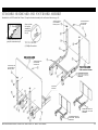
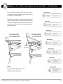
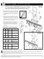
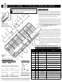
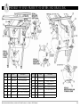
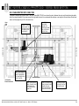
Standard Headboard and Footboard Assembly
Standard beds do NOT include Staff Control. (Complete footboard assembly with staff control shown on page 11)
tube end caps are
pre-assembled on
Mounting tubes
close-up of Hair
pin clip (#8)
inserted into
hole in clevis
pin (#7)
to safely remove Hair pin clip
grasp on circular end and pull.
threaded Inserts are
pre-assembled
on Footboard
Tools Needed:
(1) Phillips Screwdriver
HEADBOARD
tube end caps are
pre-assembled on
Mounting tubes
threaded Inserts are
pre-assembled
on Headboard
FOOTBOARD
Staff control not shown.
Main Frame
Weldment
FootBoArd posItIon
For 84” Bed - 1st HoLe
FroM end
FootBoArd posItIon
For 76” Bed - 3rd HoLe
FroM end
Basic American Medical products, a division of GF Health products, Inc. • Matrix II • rev d Manual
p10
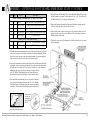
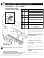
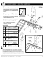
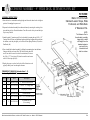
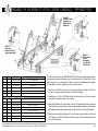
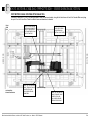
A ssembly - OPTIONAL foot board EMBEDDED STAFF CONTROL
Item #
Qty
Part #
Description
STAFF CONTrOL ASSEMBLy KIT (ZL788053) INCLuDES:
1
1
Z53650
2
1
999-0775-901
Staff Control Assembly with Cables
3
1
999-0775-006G
Wide Staff Control Shroud
4
6
100-5506-002
#6 x .50” Phillips Truss Head Screws (Blk)
5
3
100-1100-024
4” Nylon Cable Tie
4. Insert the Footboard Mounting Tubes into the Main Bed Frame Tubes so that
the holes match up as shown. Secure with two 5/16 x 1-1/2” Clevis Pins (#6)
and Hair Pin Clips (#7) (1 each per bed frame tube).
Std. Oak Head- & Footboard (with cut out)
Mounting Tube to Main Frame Hardware
6
2
100-7931-007
5/16 x 1.50” Clevis Pin w/hole (existing)
7
2
100-2001-006
1-9/16 x .072 Hair Pin Clip (existing)
5. Unplug the Pendant cable from the Extension Cable that’s already attached
to the left side frame rail at the foot end of the bed.
6. Plug the male staff control cable into the cable extension that has been
plugged into the control box in the HB Port. Plug the Pendant cable into
the female staff control cable.
7. Tighten all screws on the Footboard with a phillips screwdriver. Be careful
not to overtighten.
1. Assemble the footboard mounting tubes to the “staff control footboard” as shown
on the previous pages if not already assembled. Note that the standard footboard
does not have the cut outs for the staff control assembly. A separate footboard
with cut outs must be ordered for the staff controller option.
2. Facing the footboard from the foot-end of the bed, carefully thread the male
and female staff control cables through the hole in the footboard and position
the staff control assembly (#2) into the pre-formed slot on the footboard,
making sure all screw holes line up correctly. Using two black
#6 X .50” Phillips Truss Head Screws (#4), from the back of
the footboard secure the Staff Control via the outermost holes.
3. Place the Staff Control Shroud (#3) over the cables on the back
of the footboard and attach with four black #6 X .50” Phillips
Truss Head Screws (#4). Lightly tighten all screws with a phillips
screwdriver. Tie the cables to the mounting tubes with ties (#5).
close-up of Hair
pin clip (#6)
inserted into
hole in clevis
pin (#7)
to safely remove Hair pin clip
grasp on circular end and pull.
Tools Needed:
(1) Phillips Screwdriver
Basic American Medical products, a division of GF Health products, Inc. • Matrix II • rev d Manual
p11
WALLSAVERS, MATTRESS RETAINERS
& EDEMA RATCHETS
Basic American Medical products, a division of GF Health products, Inc. • Matrix II • rev d Manual
p12
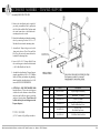
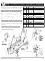
A ssembly - standard wallsaver
(with optional trapeze positioning)
1. The Matrix II 709 standard
wireform wallsaver is easily
attached to the head-end of
caster carriage. Begin by
positioning the wallsaver
(#2) on the head end with
the exposed ends (with flat
insert tabs) facing the footend of the bed.
2. From the inside, locate the
bottom last hole in the carriage
bracket on both sides of the
bed. Holding the wallsaver in a
45° position as shown, squeeze its
sides inward toward center and
insert the ends of the wallsaver
into the bracket holes. (See Detail A)
FLAt tAB
Inserted
so tHAt It
Is pArALLeL
WItH sLot In
cArrIAGe BrAcket
3. Carefully lower the wallsaver downward
until it rests on the floor. The flat insert
tab will turn within the bracket hole, locking
the wallsaver into place. (See Detail B).
FLAt tAB Locks Into
cArrIAGe BrAcket
BY turnInG It
perpendIcuLAr
once It Is
InsIde HoLe
4. The position of the wallsaver is very
important on the Matrix II bed. It has
been designed so that the bed will be
kept a safe distance from the wall
when raising or lowering the bed,
thus preventing damage to the bed
or resident/facility walls.
FLAt Insert tAB
NO SPECIAL Tools REQUIRED
Item #
Quantity
Part #
Description
1
Reference
999-0807-955G
Standard Caster Carriage Assembly
(Also works on Locking Carriage Assembly 999-0807-958G)
2
1
999-0779-180
Standard Wireform Wallsaver - 76”, 80”, or 84”
WALLsAver
posItIon For trApeZe
stAndArd
WALLsAver
posItIon
cArrIAGe BrAcket
For 80” Bed
Basic American Medical products, a division of GF Health products, Inc. • Matrix II • rev d Manual
p13
A ssembly - standard corner mattress retainers
NOTE: The Mattress retainers are interchangeable for both the head and foot ends of the bed. The foot retainers come standard with your
bed. Head retainers are optional and must be ordered separately.
1. Install the Mattress Retainers (#1) into the holes on the
corners of the Head Deck or Foot Deck.
a. Starting in a vertical position, place the ends
into the holes as shown in Figure A so that the
curved part of the retainer is facing outward.
b. Lower the mattress retainer and pivot
it into a horizontal resting position
as shown in Figure B.
Item #
1
Kit Qty.
(In sets of 2)
Kit #
999-0814-000
Single Part #
999-0814-001
Description
Corner
Mattress
Retainer
NO SPECIAL Tools
REQUIRED
Figure A
Basic American Medical products, a division of GF Health products, Inc. • Matrix II • rev d Manual
Figure B
p14
O PERATION OF OPTIONAL EDEMA FOOT RATCHET
999-0748-001
The foot ratchet allows the attendant to manually adjust the foot position for
the resident/patient. It offers five different positions for comfort versatility. It
was designed to be easily adjusted by hand.
Simply lift the foot end of the bed via the main frame and position the foot end
in one of the five slots available for the preferred foot height. To release the
ratchet so that it returns to the down position, lift the foot end to the outer most
extension of the ratchet. This will release the pin from the slots and return the
bed to the prone position.
Foot-end rAtcHet
FuLL-doWn posItIon
Foot-end rAtcHet
FuLL-up posItIon
ratchet with
5 position slots
NOTE:
The foot-end ratchet adjustment can be used
with the knee deck in any position.
Basic American Medical products, a division of GF Health products, Inc. • Matrix II • rev d Manual
p15
Accessory Assembly
Basic American Medical products, a division of GF Health products, Inc. • Matrix II • rev d Manual
p16
A ccessory Assembly - Head & Foot Half Rails
Head-End Half Rail KIT: ZA78400
(Includes part 999-0784-908G —Left side and
part 999-0784-907G - right side, plus hardware bag)
HeAd
Item # Qty.
1
1
Part #
Description
999-0784-908G
Head-End Half Rail: Left-Hand Side - 76”
Head-End Half Rail: Left-Hand Side - 80”
right
Foot-End Half Rail: Right-Hand Side - 80” Only (Not shown)
1
1
999-0794-908G
Left
Foot-End Half Rail: Left-Hand Side - 80” Only (Pg. 18)
1
Foot
Foot-End Half Rail: Right-Hand Side - 76” Only (Not shown)
1
999-0784-907G
Head-End Half Rail: Right-Hand Side - 76” (Not shown)
Head-End Half Rail: Right-Hand Side - 80” (Not shown)
HEAD
BOARD
1
1
999-0794-907G
Foot-End Half Rail: Left Hand Side - 76” Only (Pg. 18)
2
2
999-0784-100
Clevis Pin - 16mm. Dia. x 105mm. w/cross-hole,
circle cotter, lanyard cable (LBK-3-06)
and Hair Pin Clip
note:
release trigger is
located at this end.
1. All Half Rails (#1) mount to the bed in a similar fashion. Left or right
designations are based on the patient’s orientation as he/she lies in
the bed.
2. Insert the two Clevis Pins, with Circle Cotter and Lanyard Cable (#2),
into the two Half Rail arms as shown.
3. Attach the Half Rail to the bed frame brace by aligning the arms
and Clevis Pins to the holes on the brace. Slide the Clevis Pins so
that they extend past the brace on the underside of the bed.
LeFt HALF rAIL
999-0784-908G sHoWn
!
WARNING: The mattress support platform should always be placed in the flat position when not attended.
When assessing the Risk for Entrapment, you need to consider your bed, mattress, head- and footboards, half rails, assist bars,
and other accessories as an entire system. All bed systems are evaluated for compliance to the FDA/CDRH “Hospital Bed
System Dimensional and Assessment Guidance to Reduce Entrapment” guidelines.
A resident/patient’s condition could lead to resident/patient entrapment. It is extremely important to review the resident/patient’s
physical and mental condition, and initiate an appropriate individual care plan to address any entrapment risks.
Basic American Medical products, a division of GF Health products, Inc. • Matrix II • rev d Manual
4. Insert the two Hair Pin Clips (#3) into the holes in the Clevis Pins
to secure the rail to the bed.
5. IMPORTANT: Lubricate all pivot joints as needed. Aerosol White
Lithium Grease is recommended.
6. TO OPERATE: Depress the Release Trigger to lower or raise the
half rail assembly.
NO SPECIAL Tools REQUIRED
p17
80” FOOT-End Half
Rail KIT: ZA78500
76” FOOT-End Half
Rail KIT: ZA79400
Includes (part 999-0784-907G —Left side,
part 999-0784-908G —right side, two Foot
Brackets, and all mounting hardware)
Includes (part 999-0794-907G —Left side,
part 999-0794-908G —right side,
two Foot Brackets, and all
mounting hardware)
FOOT
BOARD
to safely remove Hair pin clip
grasp on circular end and pull.
note:
release trigger is
located at this end.
close-up of Hair
pin clip (#8)
inserted into
hole in clevis
pin (#7)
HeAd
note:
Pre-assembly of the
Rail Bracket to the foot
section is required before
the foot-end Half Rail
can be attached.
Please see page 19.
right
LeFt HALF rAIL
999-0784-908G sHoWn
Basic American Medical products, a division of GF Health products, Inc. • Matrix II • rev d Manual
Left
Foot
p18
A ccessory Assembly - Foot RAIL BRACKET FOR HALF RAILS
NOTE: Installation of Foot Bracket for Half Rails or Assist Bars is only necessary on the Foot Section
of the bed frame.
1. Using the outer most holes
of the Rail Bracket, install
the Bracket (#1) with two
5/16-18 x 1-3/4” Bolts (#2)
and two 5/16-18 Nylon Lock
Nuts (#3) as shown. Make
sure the longer end of the
bracket is toward the footend of the Bed Frame.
Tools Needed:
(1) 3/4” wrench
2. Use a 5/16 wrench and
secure tightly.
edGe oF
Bed
edGe oF
Bed
LeFt HoLe
ApproX.
1.571
ApproX.
1.571
rIGHt HoLe
LeFt sIde
HoLe orIentAtIon vIeW
rIGHt sIde
Basic American Medical products, a division of GF Health products, Inc. • Matrix II • rev d Manual
For 2 Half Rail Foot Brackets Order Hardware Bag/Kit: 999-0785-905
(NOTE: Two Foot Brackets & Hardware included with Half Rails in ZA78500)
Item #
Qty.
Part #
Description
1
2
999-0775-025G
Rail Bracket
2
4
100-5431-036
5/16-18 x 1-3/4 Button Head Machine Screw
3
4
100-6731-006
Thin Nylon Lock Nut 5/16-18
For 1 Assist Bar Foot Bracket Order Hardware Bag/Kit: 999-0786-995
(NOTE: Single Foot Bracket & Hardware included with Assist Bar in ZA80350)
Item #
Qty.
Part #
Description
1
1
999-0775-025G
Rail Bracket
2
2
100-5431-036
5/16-18 x 1-3/4 Button Head Machine Screw
3
2
100-6731-006
Thin Nylon Lock Nut 5/16-18
p19
A ccessory Assembly - Foot-END ASSIST BAR
NOTE: Pre-assembly of the Rail Bracket to the foot section is required
before the Foot-End Assist Bar can be attached. Please see page 19.
optIon 1
1. With the Assist Bar (#1) bracket facing inward toward the bed as
shown, align the two holes on the bracket with the first and third
holes (from the head-end of the bed) of the pre-welded head deck
bracket (#2)
2. For the quick release option, insert the Clevis Pin end of the two
Lanyard assemblies (3a) from the outside into the assist bar bracket
holes. Insert the hair pins on the opposite end of the lanyard
assemblies (3b) into the holes of the clevis pins.
to safely remove Hair pin clip
grasp on circular end and pull.
3. For a fixed attachment option, insert two cap screws (#4) from
the outside into the assist bar bracket holes. Secure the screws
by attaching two Thin Nylon Lock Nuts (#5).Tighten with two
13/16 wrenches.
Order Kit #ZA80350 - Includes Bracket and Hardware
Item #
Qty.
Part #
Description
1
1
999-0803-902G
Assist Bar - Foot End
2
1
999-0786-995
(included)
Attach Foot Rail Bracket
(see page 19)
not
shown
2
100-4710-003
1.00” Dia. End Cap
close-up of Hair
pin clip (#8)
inserted into
hole in clevis
pin (#7)
optIon 2
1
4
Option 1: Quick Release (in Hdw Bag 999-0803-905)
3
2
999-0784-100
Quick Release
Lanyard Assembly
Option 2: Fixed Attachment (in Hdw Bag 999-0803-905)
!
4
2
100-5463-004
5
2
100-6763-001
5/8-11 x 4.50”
Hex Head Cap Screw
5/8-11 Thin Nylon
Lock Nut
5
2
WARNING: The mattress support platform should always be placed in the flat position when not attended.
When assessing the Risk for Entrapment, you need to consider your bed, mattress, head- and footboards, half rails, assist bars, and other accessories as an entire system. All bed systems are evaluated for compliance to the
FDA/CDRH “Hospital Bed System Dimensional and Assessment Guidance to Reduce Entrapment” guidelines.
A resident/patient’s condition could lead to resident/patient entrapment. It is extremely important to review the resident/patient’s physical and mental condition, and initiate an appropriate individual care plan to address any
entrapment risks.
Basic American Medical products, a division of GF Health products, Inc. • Matrix II • rev d Manual
p20
A ccessory Assembly - HEAD-END ASSIST BAR
optIon 1
1. With the Assist Bar (#1) bracket facing inward toward the bed as
shown, align the two holes on the bracket with the first and third
holes (from the head-end of the bed) of the pre-welded head deck
bracket (#2)
2. For the quick release option, insert the Clevis Pin end of the two
Lanyard assemblies (3a) from the outside into the assist bar bracket
holes. Insert the hair pins on the opposite end of the lanyard
assemblies (3b) into the holes of the clevis pins.
to safely remove Hair pin clip
grasp on circular end and pull.
3. For a fixed attachment option, insert two cap screws (#4) from
the outside into the assist bar bracket holes. Secure the
screws by attaching two Thin Nylon Lock Nuts (#5).
Tighten with two 13/16 wrenches.
Order Kit #ZA80300
Item #
Qty.
Part #
Description
1
1
999-0803-902G
Assist Bar - Head End
2
1
-
Head Deck Rail Bracket
(pre-welded on deck)
not
shown
2
100-4710-003
1.00” Dia. End Caps
optIon 2
Quick Release Option 1 (in Hdw Bag 999-0803-905)
3
2
999-0784-100
Fixed Attachment Option 2 (in Hdw Bag 999-0803-905)
!
4
2
100-5463-004
5
2
100-6763-001
1
Quick Release
Lanyard Assembly
5/8-11 x 4.50”
Hex Head Cap Screw
5/8-11 Thin Nylon
Lock Nut
4
close-up of Hair
pin clip (#8)
inserted into
hole in clevis
pin (#7)
WARNING: The mattress support platform should always be placed in the flat position when not attended.
When assessing the Risk for Entrapment, you need to consider your bed, mattress, head- and footboards,
half rails, assist bars, and other accessories as an entire system. All bed systems are evaluated for compliance
to the FDA/CDRH “Hospital Bed System Dimensional and Assessment Guidance to Reduce Entrapment” guidelines.
5
5
A resident/patient’s condition could lead to resident/patient entrapment. It is extremely important to review the resident/
patient’s physical and mental condition, and initiate an appropriate individual care plan to address any entrapment risks.
Basic American Medical products, a division of GF Health products, Inc. • Matrix II • rev d Manual
p21
A ccessory Assembly - standard 4” extension pan Kit
ASSEMBLY INSTRucTIONS
1. Raise the bed to a comfortable working height and elevate the knee deck to its highest
position. Now unplug the power cord.
2. Separate the footboard assembly from the main frame by removing the existing clevis
pins and hair pin clips. Put aside hardware. You will reuse the clevis pins and hair pin
clips in step 4 below.
3. Attach the standard 4” extension pan (#1) to the foot deck using two 5/16-18 x .75”
carriage bolts (#2) through the top designated holes and secure tightly with two wing
nuts (#3) from the bottom.
PIcTuRED:
Matrix II Foot end with
standard- Footboard,
Leveler straps, and
4” extension pan.
4. Now reinstall the footboard assembly by sliding the mounting tubes into the frame,
lining up the holes as shown (Note: The last hole in the tube will now
be one hole closer to the end of the main frame). Re-insert the 5/16 x
1.75” clevis pins (#4) from the outside in and secure with 1-9/16 hair
pin clips (#5).
5. Replug the power cord and verify that all bed functions work properly
and all parts have adequate clearance.
STANDARD KIT: #ZA71900 (Includes Items 1 - 4)
Hardware Bag 999-0719-995)
Item #
Qty.
Part #
Description
1
1
999-0719-001G
Standard 4” Extension Pan
2
2
100-5231-001
5/16-18 x .75” Carriage Bolt
3
2
100-6931-001
5/16-18 Wing Nut
4
2
100-7931-006
5/16 x 1.75” Clevis Pin w/Hole
5
2
100-2001-006
1-9/16 Hair Pin Clip
(Use existing)
Basic American Medical products, a division of GF Health products, Inc. • Matrix II • rev d Manual
Reuse existing Hair Pin Clips
p22
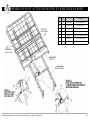
A ccessory Assembly - 42” wide deck (order Kit# ZA811000)
!
Foot-end
Half rail
ASSEMBLY INSTRucTIONS
WArnInG:to reduce the risk of entrapment it is highly recommended to include both
wide head- & footboards and assist devices when purchasing any 42” expansion kit.
A variety of complete kits are available.
1. Align the right-hand foot assembly above the foot and knee decks with the angle hooks
facing downward and toward the foot end. The right knee extension (#4) hook should
be positioned just above the knee deck (toward the head end). Place the assembly flat
on the two decks making sure they are flush with the decks’ sides. Slide the foot extension’s
hooks onto the foot-end decks. Follow the same procedure for the left side.
2. The right-hand head assembly should be aligned above the head-deck as shown, with
the angle hook positioned downward and just above the head deck. Place the assembly
flat on the head deck and seat pan making sure they are flush with the deck’s side. Slide
the extension assembly toward the foot end to lock the extension’s hooks onto the head
deck and pan seat. Make sure that the right-hand seat pan extension (#3) is on the
outside of the right-hand knee extension (#4). Follow the same
procedure for the left side.
Wide
Footboard
example of right-side
expansion pans with Foot-end
Assist device & Wide Footboard
3. Locate the two 5/16-18 x .375” Hex Washer Head Machine Screws (#9)
and the two Self-Wrenching Nuts (#8) in your hardware bag. From the outside, insert a self-wrenching nut so that the square part of the nut fits into the
square hole of the head assembly mounting arm and the end extends through
the hole in the foot mounting arm. From the inside, screw in a machine screw and
tighten using a 1/2” wrench. Follow the same procedure for the opposite side.
4. Locate the eight 5/16 x 3.50” Clevis Pins (#10) and eight 1-9/16 Hair Pin Clips
(#11) in your hardware bag. From the outside, insert the clevis pins through the
pre-drilled holes in the sides of the right- and left-hand head and foot expansion
pans. From the inside, insert the hair pin clips into the exposed holes on the clevis
pins to secure the pins to all decks.
80” WIDE KIT WITHOuT BOARDS: #ZA811000 (Includes Items 1 - 11)
76” WIDE KIT WITHOuT BOARDS: #ZA846000 (Includes Items 1 - 11)
Packaged in four assemblies for easy
assembly (kit includes all mounting hardware)
5/16-18 Machine screws
Wide Kit Mattress Retainers
self-Wrenching nuts
Right Side Foot Assembly Right Head Foot Assembly
Item #
Qty.
Part #
Description
1
1
999-0811-921G
Left-Hand Head Extension Weldment
2
1
999-0811-922G
Right-Hand Head Extension Weldment
3
2
999-0811-004G & 005G
Left- & Right-Hand Seat Pan Extension
4
1
999-0810-012G
Right-Hand Knee Extension
5
1
999-0810-002G
Left-Hand Knee Extension
6
1
999-0811-932G
80” Right-Hand Foot Extension Weldment
7
1
999-0811-931G
80” Left-Hand Foot Extension Weldment
Not Shown
1
999-0846-932G
Opt. 76” Right-Hand Foot Extension Weldment
Not Shown
1
999-0846-931G
Opt. 76” Left-Hand Foot Extension Weldment
Both kits Include Hardware Box: 999-0811-950 which has the following . . .
Left Side Foot Assembly
Left Side Head Assembly
the Matrix II expansion kit uses
special bolt-on mattress retainers
(999-0810-008) order kIt#
999-0810-000 for two retainers.
Basic American Medical products, a division of GF Health products, Inc. • Matrix II • rev d Manual
8
6
999-0032-010
Self-Wrenching Nut (4 pre-assembled on decks)
9
6
100-5431-002
5/16-18 x .375” HWHMS (4 pre-assembled on decks)
10
8
100-7931-008
5/16 x 3.50” Clevis Pin w/Hole
11
8
100-2001-006
1-9/16 Hair Pin Clip
p23
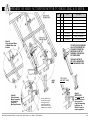
A ccessory Assembly - 4” wide deck extension pan KIT
ASSEMBLY INSTRucTIONS
1. Raise the bed to a comfortable working height and elevate the knee deck to its highest
position. Now unplug the power cord.
2. Separate the footboard assembly from the main frame by removing the existing clevis
pins and hair pin clips. Put aside hardware. You will reuse the clevis pins and hair pin
clips in step 4 below.
3. Attach the wide 4” extension pan (#1) to the foot deck by inserting the two 1/4-20 x .75”
Carriage Bolts (#2) from your hardware bag through the top designated holes and, from
the bottom, secure the pan tightly to the deck with two Spring Washers (#3) and two
Pan Knobs (#4).
4. Now reinstall the footboard assembly by sliding the mounting tubes into the frame,
lining up the holes as shown (Note: The last hole in the tube will
now be one hole closer to the end of the main frame). Re-insert
the 5/16 x 1.75” clevis pins (#5) from the outside in and secure
with 1-9/16 hair pin clips (#6).
PIcTuRED:
Matrix II Foot end with
standard Leveler straps, Wide
Footboard, and Wide deck
4” extension pan.
note:
the extension pan for
the wide deck is actually
bigger (both in width
and length) than the
standard extension
pan but still only
extends the bed
deck four inches.
5. Replug the power cord and verify that all bed functions work
properly and all parts have adequate clearance.
STANDARD KIT: #ZA82100 (Includes Items 1 - 5)
Hardware Bag 999-0821-995)
Item #
Qty.
Part #
Description
1
1
999-0821-001G
4” Wide Kit Extension Pan
2
2
100-5225-009
1/4-20 x .75” Carriage Bolt
3
2
100-8525-001
1/4 Spring Lock Washer
4
2
999-0810-009
Black Pan Knob
5
2
100-7931-006
5/16 x 1.75” Clevis Pin w/Hole
6
2
100-2001-006
1-9/16 Hair Pin Clip
(Use existing)
Basic American Medical products, a division of GF Health products, Inc. • Matrix II • rev d Manual
Reuse existing Hair Pin Clips
p24
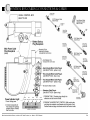
A ccessory Assembly - Trapeze support
Assembly Kit# 999-0790-901
1. Remove the headboard panel assembly if
previously assembled to bed by pulling out
the Clevis Pins and Hair Pin Clips that attach
the main frame tubes to the headboard’s
mounting tubes and set aside.
2. Detach the headboard panel from the mounting
tubes by removing the four 1/4-20 x 1.5”
Machine Screws from the mounting tubes.
3. Assemble the Trapeze Support to the bed
frame using the two Clevis Pins and Hair
Pin Clips you previously removed from the
headboard’s mounting tubes.
4. Insert a 1/4-20 x 2.5” Carriage Bolt (#5) into
the vertical support as shown and fasten with
a 1/4-20 Hex Head Lock Nut (#6).
5. Assemble the headboard to Trapeze Support
using the supplied four 1/4-20 x 1.75” Machine
Screws (#3) from your hardware bag, threading
them through the headboard into the 1/4-20
inserts. DO NOT OVERTIGHTEN.
6. OPTIONAL—FOr TMI TrAPEZE BAr
Insert the Sleeve (#7) into the vertical support
with the slot on the bottom as shown. Rotate
the sleeve until it falls into place over the bolt
and into a locked position. (Top of Sleeve will
be flush with top of vertical support on the
Trapeze Adaptor.)
Tools Needed:
(1) 7/16” wrench & (1) phillips screwdriver
Item #
Qty.
Part #
Description
1
1
999-0790-901G
Trapeze Support Assembly
2
1
Headboard
Headboard - 8” Boring
3
4
100-7025-004
1/4-20 x .60 Insert
4
4
100-5425-014
5
1
100-5425-059
1/4-20 x 1.75” Phillips
Pan Head Machine Screw
1/4-20 x 2.50”
Hex Head Cap Screw
6
1
100-6725-005
Basic American Medical products, a division of GF Health products, Inc. • Matrix II • rev d Manual
1/4-20 Hex Head Lock Nut
p25
PARTS & HARDWARE
Basic American Medical products, a division of GF Health products, Inc. • Matrix II • rev d Manual
p26
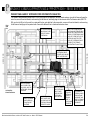
A
SSEMBLY OF HEAD, KNEE, & FOOT DECKS TO MAIN FRAME
OPTIONAL
PAN DEcKING
(See chart below
for parts listings)
Basic American Medical products, a division of GF Health products, Inc. • Matrix II • rev d Manual
Item #
Qty.
Part #
Description
1
1
999-0807-900G
Main Frame Weldment
2
1
999-0779-920G
80” Grid Head/Back Deck Weldment
UPPER
LEFT
1
999-0796-982G
80” Pan Head/Back Deck Weldment
3
1
999-0779-930G
80” Grid Foot Deck Weldment
Not shown
1
999-0775-936G
Opt. 76” Grid Foot Deck Weldment
UPPER
LEFT
1
999-0796-983G
80” Pan Foot Deck Weldment
Not shown
1
999-0796-986G
76” Pan Foot Deck Weldment
4
1
999-0779-940G
80” Grid Knee Deck Weldment
UPPER
LEFT
1
999-0796-984G
80” Pan Knee Deck Weldment
5
8
100-5431-002
6
6
999-0032-010
5/16-18 x .375”
Hex Washer Head Machine Screw
Short Self-Wrenching Nut
7
2
100-7950-004
1/2 x 2.00” Clevis Pin w/hole
8
2
100-7518-001
7/16-1/2” Circle Cotter
9
2
999-0807-036G
Leveler Strap Bracket
10
2
100-5231-005
5/16-18 x 1.75” Carriage Bolt
11
2
100-6731-006
5/16-18 Thin Nylon Lock Nut
12
2
806-0277-008
Long Self-Wrenching Nut
p27
A
SSEMBLY OF MAIN FRAME TO U-LEVERS AND DRAG LINK
Item #
Qty.
Part #
Description
Item #
Qty.
Part #
Description
1
1
999-0807-900G
Main Frame Weldment
8
2
100-7950-005
.50” x 1.75” Clevis Pin w/Hole
2
1
999-0807-903G
Foot U-Lever Weldment
9
2
100-7500-015
.50” Reg. .62 Rue Ring
3
1
999-0807-913G
Head U-Lever Weldment
10
4
999-0775-001
Half Moon Cap
4
1
999-0807-906G
Drag Link Weldment
11
6
100-4700-017
1.00” x 2.00” Rect. Tube End Cap
5
4
999-0779-100
1/2-13” x 2.50” Shoulder Bolt
12
4
100-4700-015
1.00” Square Tube End Cap
6
8
100-8601-001
.516ID x 1.25OD x .062Thk Washer
13
2
100-8600-015
1.00” x .25” Thk Duopreen Disk
7
4
100-6750-006
1/2-13 Low Nylon Lock Nut
14
4
100-4550-010
Button Stop
Basic American Medical products, a division of GF Health products, Inc. • Matrix II • rev d Manual
p28
A
SSEMBLY OF U-LEVERS TO STD. CASTER CARRIAGE - 999-0807-955G
Detail B
Locking caster
assembly on
right side of
Head end
Detail a
U-Lever to
caster Brackets
(typical assembly)
Detail c
non-Locking
caster
assembly
on Left side
of Foot end
Item #
Qty.
Part #
Description
1
1
999-0807-903G
Foot U-Lever Weldment
2
1
999-0807-913G
Head U-Lever Weldment
3
4
999-0775-001
Half Moon Cap
4
4
999-0779-100
1/2-13NC x 2.50” Long Button Head Cap Screw (T55)
5
8
100-8601-001
.516ID x 1.25”OD x .062”Thk. Nylon Washer
6
4
100-6750-006
1/2-13 Low Nylon Lock Nut
Standard Caster Carriage Assembly 999-0807-955G Includes the following parts
7
1
999-0807-905G
Caster Carriage Weldment
8
8
999-0775-001
Half Moon Cap (on Locking Carriage)
9
2
100-6330-061
3” Twin Non-Locking Caster
10
2
100-6330-062
3” Twin Locking Caster
11
4
100-6744-001
7/16-14 Nylon Lock Nut
12
4
100-4700-017
1.00” x 2.00” Rectangular End Cap
13
4
100-4200-004
1.25” Square Plastic Plug
14
4
100-4717-002
1.75” x 10-12GA Round End Cap
Basic American Medical products, a division of GF Health products, Inc. • Matrix II • rev d Manual
the standard caster carriage (999-0807-955G) should come pre-assembled. callouts
for replacing the casters and caps on both the head and foot end (details B & c) have
been included for your convenience. to attach or detach the standard caster carriage
from the Matrix II u-levers, please follow the instructions below.
1. place the four Half Moon caps (#3) into the bottoms of both u-levers (#1 & #2) and
into the four upright mounting brackets on the caster carriage.
2. Locate the four 1/2-13 x 2.50” Button Head cap screws (#4) and, from the outside,
insert them in the bottom holes of the u-levers.
3. place a nylon Washer (#5) onto the ends of each of the exposed ends of the cap screws.
carefully position the u-lever legs onto the upright brackets so that the nylon washers
rest between them. push the cap screws through the holes in the upright brackets.
4. slide the remaining nylon Washers (#5) onto the cap screws and secure using four
1/2-13 nylon Lock nuts (#6). tighten all hardware using a 5/16 crescent/socket wrench
and a t55 torx wrench.
p29
A
SSEMBLY OF U-LEVERS TO LOCKING CASTER CARRIAGE - 999-0807-958G
the caster carriage with Locking Mechanism (999-0807-958G) should come preassembled. callouts for replacing the casters and caps on both the head and foot end
(details B & c) have been included for your convenience. to attach or detach the locking
caster carriage from the Matrix II u-levers, please follow the instructions below.
1. place the four Half Moon caps (#3) into the bottoms of both u-levers (#1 & #2)
and into the four upright mounting brackets on the caster carriage.
Item #
Qty.
Part #
Description
1
1
999-0807-903G
Foot U-Lever Weldment
2
1
999-0807-913G
Head U-Lever Weldment
3
4
999-0775-001
Half Moon Cap
4
4
999-0779-100
1/2-13NC x 2.50” Large Button Head Cap Screw (T55)
5
8
100-8601-001
.516ID x 1.25”OD x .062”Thk. Nylon Washer
6
4
100-6750-006
1/2-13 Low Nylon Lock Nut
Optional Locking Caster Carriage Assembly (999-0807-958G) includes the following parts:
2. Locate the four 1/2-13 x 2.50” Button Head cap screws (#4) and, from the outside,
insert them in the bottom holes of the u-levers.
3. place a nylon Washer (#5) onto the ends of each of the exposed ends of the cap
screws. carefully position the u-lever legs onto the upright brackets so that the
nylon washers rest between them. push the cap screws through the holes in the
upright brackets.
4. slide the remaining nylon Washers (#5) onto the cap screws and secure
using four 1/2-13 nylon Lock nuts (#6). tighten all hardware using a 5/16
crescent/socket wrench and a t55 torx wrench.
7
1
999-0807-905G
Locking Carriage Weldment
8
8
999-0775-001
Half Moon Cap (On Locking Carriage)
7/16-14 Thin Nylon Lock Nut
9
4
100-6744-002
10
4
100-6300-061
3” Twin Non-Locking Caster
11
4
100-4700-017
1.00” x 2.00” Rectangular End Cap
12
4
100-4200-004
1.25” Square Plastic Plug
13
4
100-4717-002
1.75” x 10-12GA Round End Cap
14
2
999-0809-014
Caster Cap (Only on Locking Mechanism)
Detail c
non-Locking
caster on
Foot end with
Keeper at
Head end
Detail a
U-Lever to
caster Brackets
(typical assembly)
Detail B
non-Locking
caster on
Locking
mechanism
at Foot end
Basic American Medical products, a division of GF Health products, Inc. • Matrix II • rev d Manual
p30
ELECTRONICS
Basic American Medical products, a division of GF Health products, Inc. • Matrix II • rev d Manual
p31
A
SSEMBLY OF HEAD ACTUATOR/MOTOR TO HEAD DECK & FRAME
Basic American Medical products, a division of GF Health products, Inc. • Matrix II • rev d Manual
Item #
Qty.
Part #
Description
1
1
999-0807-900G
Main Frame Weldment
2
1
999-0779-920G
Head/Back Deck Weldment
3
1
999-0775-052
Head Actuator/Motor (LA27)
4
1
999-0779-300
J-Box/Control Box CB6 (LA27)
5
1
999-0779-300_clip
J-Box/Control Box Clip
6
2
100-7500-015
.50” Reg. .062 Rue Ring
7
1
999-0808-455
12mm x 55mm Clevis Pin w/Hole
8
1
100-5712-002
#12 x .50” PH Self-Tapping Screw
p32
A
SSEMBLY OF FOOT ACTUATOR/MOTOR TO KNEE DECK & FRAME
KNEE DECK
999-0779-940G
Item #
Qty.
Part #
Description
1
1
999-0807-900G
Main Frame Weldment
2
1
999-0779-930G
Foot Deck Weldment
3
1
999-0779-940G
Knee Deck Weldment
4
1
999-0775-053
Foot Actuator/Motor (LA27)
5
1
999-0808-455
12mm Dia. x 55mm Clevis Pin w/Hole
6
2
999-7500-015
.50” Reg. .062 Rue Ring
7
1
999-0775-445
12mm Dia. x 45mm Clevis Pin w/Hole
FOOT DECK
999-0779-930G
MAIN FRAME
999-0807-900G
Basic American Medical products, a division of GF Health products, Inc. • Matrix II • rev d Manual
p33
A
SSEMBLY OF HI/LO ACTUATOR/MOTOR TO DRAG LINK & U-LEVER
Item #
Qty.
Part #
Description
1
1
999-0807-900G
Main Frame Weldment
2
1
999-0807-906G
Drag Link Weldment
3
1
999-0807-913G
Head-End U-Lever Weldment
4
1
999-0775-445
12mm Dia. x 45mm Clevis Pin w/Hole
5
1
100-2001-006
1-9/16 Hair Pin Clip
6
2
100-7950-004
.50” x 2.00” Clevis Pin w/Hole
7
1
999-7500-015
.50” Reg. .062 Rue Ring
8
1
999-0808-950
Hi/Lo Actuator/Motor Assembly
Detail a
Hi/Lo actuator motor
to middle Drag Link
Bracket
to repLace tHe matrIX II
HI/Lo actUator/motor
YoU mUSt orDer tHe
entIre HI/Lo motor
aSSemBLY 999-0808-950 pIctUreD Here
tHe HI/Lo motor IS
not SoLD SeparateLY
For tHe matrIX II BeD.
top HoLes
Are not used
Detail B
Hi/Lo actuator
motor assembly
to Head end
Drag Link
mounting Bracket
use the middle hole on
the head-end drag link
mounting bracket to
attach the control arm
plates of the hi/lo motor
assembly to the drag link
Basic American Medical products, a division of GF Health products, Inc. • Matrix II • rev d Manual
Detail c
Important:
You must use the
second hole from
the top on the
drag link mounting
bracket on all
matrix II beds for
proper operation.
p34
CABLING
Basic American Medical products, a division of GF Health products, Inc. • Matrix II • rev d Manual
p35
C
ONTROL BOX CABLING CONNECTIONS & cables
sInGLe controL BoX
999-0779-300
Green
Blue
controller Hi/Lo Motor
Yellow
Blue
Yellow
Foot Motor Hi/Lo Motor Head Motor
LABEL LEGEND
Basic American Medical products, a division of GF Health products, Inc. • Matrix II • rev d Manual
p36
H ead motor CABLING (999-0778-204) - VIEWED FROM BOTTOM
HEAD MOTOR cABLE ROuTING WITH cABLE TIES
the Head Motor cable (999-0778-204) is very short on the Matrix II bed. It runs directly underneath the control box and plugs in port #1. cable tie
the Head cable together with the power cable, pendant cable, and pendant extension cable just above the power cable plug-in as shown.
Foot end
HeAd end
Right
Head
End
Left Head End Viewed From Bottom
HeAd cABLe pLuGs
Into port #1 on
controL BoX.
Basic American Medical products, a division of GF Health products, Inc. • Matrix II • rev d Manual
cABLe tIe HeAd
Motor cABLe,
poWer cord,
pendAnt cABLe
And eXtensIon
cABLe toGetHer
p37
H
ILO motor CABLING (999-0775-202) - viewed FROM BOTTOM
HI/LO cABLE ROuTING WITH cABLE TIES
the Matrix II features only one Hi/lo Motor. the Hi/Lo cable (999-0775-202) runs above the motor (between the motor and the deck) and gets cable
tied to the drag link bracket. It then runs across to the right main frame rail, runs underneath the seat pan, runs along the left main frame rail and head
motor, and then plugs into port #2 on the control box.
cABLe tIe tHe HI/Lo
Motor cABLe to
tHe FIrst HoLe In
tHe MIddLe drAG
LInk BrAcket
cABLe tIe tHe
HI/Lo cABLe
Around tHe
rIGHt MAIn FrAMe
rAIL Just BeLoW
tHe seAt pAn
Foot end
HeAd end
Right
Head
End
cABLe tIe HI/Lo Motor
cABLe & Foot cABLe to
BrAcket underneAtH
seAt pAn BetWeen pAn
And Foot Motor
Left Head End Viewed From Bottom
cABLe tIe HI/Lo Motor
cABLe, pendAnt cABLe,
poWer cord, And
Foot cABLe Around
FrAMe rAIL
Basic American Medical products, a division of GF Health products, Inc. • Matrix II • rev d Manual
cABLe tIe HI/Lo Motor
cABLe, pendAnt cABLe
poWer cord, And
Foot cABLe Around
HeAd Motor cAsInG
HI/Lo Motor cABLe
pLuGs Into port#2
on controL BoX
p38
F
oot motor CABLING (999-0775-201) - VIEWED FROM BOTTOM
FOOT MOTOR cABLE ROuTING WITH cABLE TIES
Foot Motor cable (999-0775-201) runs along the motor, under the seat pan bracket, along the left side frame rail from Foot Actuator/Motor and plugs
into port #3 on the control Box. cable tie cable to frame and brackets as indicated.
cABLe tIe Foot Motor
cABLe & HI/Lo cABLe to
BrAcket underneAtH
seAt pAn BetWeen pAn
And Foot Motor
Foot Motor cABLe
pLuGs Into port#3
on controL BoX
(port #4 Is not used)
Foot end
HeAd end
Right
Head
End
Left Head End Viewed From Bottom
cABLe tIe Foot Motor
cABLe, pendAnt cABLe,
poWer cord, And
HI/Lo cABLe Around
FrAMe rAIL
Basic American Medical products, a division of GF Health products, Inc. • Matrix II • rev d Manual
cABLe tIe Foot Motor
cABLe, pendAnt cABLe
poWer cord, And
HI/Lo cABLe Around
HeAd Motor cAsInG
p39
P
Right
Head
End
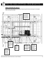
endant CABLING (999-0775-305 & 999-0779-200) - FROM BOTTOM
PENDANT cABLE AND 30” ExTENSION cORD ROuTING WITH cABLE TIES
the pendant cable (attached to pendant 999-0775-305) runs along the left underside of the main frame’s seat pan, along the left frame rail toward the
control box, around the vertical bracket, continues along the left frame rail, and finally plugs into the extension cable. the extension cable (999-0779200) runs from the HB port in the control box, underneath the box, gets cable tied to the power cable, runs around the vertical bracket, continues along
the left frame rail and plugs into the pendant cable. secure both cables with ties to frame and brackets as shown.
cABLe tIe 30” eXtensIon cABLe
(999-0779-200) And pendAnt cABLe
Around end oF MAIn FrAMe rAIL one end oF tHe eXtensIon cABLe
pLuGs Into tHe HB port on tHe
controL BoX And tHe otHer
pLuGs Into tHe pendAnt cABLe
AttAcHed to tHe pendAnt/
HAnd controLLer (999-0775-305).
30” eXtensIon cABLe
(999-0779-200) pLuGs
Into port #HB on
controL BoX
Left Head End Viewed From Bottom
cABLe tIe pendAnt
cABLe, poWer cord,
HI/Lo cABLe, And Foot
Motor cABLe, Around
FrAMe rAIL
cABLe tIe pendAnt
cABLe (neAr coIL)
to HoLe In seAt
pAn FrAMe
cABLe tIe pendAnt
cABLe, poWer cord,
HI/Lo cABLe, And Foot
Motor cABLe, Around
HeAd Motor cAsInG
Basic American Medical products, a division of GF Health products, Inc. • Matrix II • rev d Manual
cABLe tIe pendAnt
cABLe, eXtensIon
cABLe, poWer
cord, And HeAd
Motor cABLe
toGetHer Here
cABLe tIe
pendAnt &
eXtensIon
cABLes &
Ground
WIre to
HoLe In MAIn
FrAMe rAIL
Foot end
HeAd end
cABLe tIe pendAnt
& eXtensIon cABLes
& poWer cord Ground
WIre toGetHer Here
run pendAnt &
eXtensIon cABLes
tHrouGH FrAMe
rAIL BrAcket And
cABLe to tHe MAIn
FrAMe rAIL ABove
tHe BrAcket
p40
P
OWER CORD CABLING (999-0775-208) - VIEWED FROM BOTTOM
POWER cORD ROuTING WITH cABLE TIES
power cord (999-0775-208) runs from the control Box toward the head-end along the left side frame rail and plugs into the wall receptacle.
cable tie to main frame rail as indicated.
Left
Head
End
6th Hole
5th Hole
4th Hole
3rd Hole
cABLe tIe poWer cord,
Foot Motor cABLe,
pendAnt cABLe And
HI/Lo cABLe Around
HeAd Motor cAsInG
2nd Hole
1st Hole
to WALL socket
Right
Head
End
cABLe tIe poWer
cord tHrouGH
3 sQuAre HoLes In
FrAMe rAIL neAr
HeAd end
cABLe tIe poWer
cord Around end
oF MAIn FrAMe
rAIL, Just pAst
vertIcAL BrAcket
cABLe tIe
poWer cord
Around
FrAMe rAIL
Basic American Medical products, a division of GF Health products, Inc. • Matrix II • rev d Manual
cABLe tIe poWer
cord, HeAd Motor
cABLe, pendAnt cABLe
And eXtensIon cABLe
toGetHer Here
pLuG poWer
cord Into sIde
oF controL BoX.
MAke sure It
Locks Into pLAce
WItH red tABs.
p41
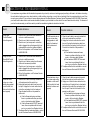
E
lectronic Troubleshooting
If you experience any problems with the electrical components of your bed (i.e. motors not working properly resulting in the head or foot decks not working,
the entire bed not raising up or down, hand controller or staff controller not working, or control box not working) follow the procedures below to see if they
can solve your problem. If you continue to have problems please call the Basic American customer service department at 800-365-2338. please have
your bed’s serial number and/or model number available (located on your bed label on either side of the main frame below the decks). to determine if
your bed is under warranty you will also need to provide the manufacturing date also located on the label.
event
possible solutions
event
possible solutions
using Hand
control/pendant
but nothing works
1. check to see if lockout has been selected on
lock outs or staff/nurse control.
2. check to see if cable is securely inserted.
3. check to see if you have power - control box
cable is plugged into wall and green light is on
underneath the control box (where available).
4. did not fix the problem - call customer service
at 800-365-2338.
Foot/knee decks do not
go up or down when
using pendant or staff
control but head and
hi/lo functions work
properly
using Foot end
nurse/staff control
but nothing works
1. check to see if lockout has been selected on
lock outs or staff/nurse control.
2. check to see if cables running from the nurse/
staff control are securely inserted.
3. check to see if you have power - control box
cable is plugged into wall and green light is on
underneath the control box.
4. did not fix the problem - call customer service
at 800-365-2338.
1. check to see if cable is securely inserted both
at the motor end and the control box.
2. unplug the foot motor cable from the control
box port. unplug the head motor cable from
the control box and replug it into the foot port.
press the foot function on the pendant or
staff control.
a) If the head deck raises and lowers,
there is a problem with either your foot
motor or foot motor cable. replace.
b) If the head deck does not raise and
lower, there is a problem with the foot
port on your control box. replace the box.
3. to replace either the foot motor/cable or control
box call customer service at 800-365-2338.
entire bed does not go
up or down when using
pendant or staff control
(hi/lo function) but head
and foot functions work
properly
1. check to see if cables are securely inserted
both at the motor end and the control box.
2. unplug one of the hi/lo motor cables from the
control box port. unplug the foot or head motor
cables from the control box and replug it into
the hi/lo port. press the hi/lo function on the
pendant or staff control.
a) If the head/foot deck raises and lowers,
there is a problem with either your hi/lo
motor or hi/lo motor cable. replace.
b) If the head/foot deck does not raise and
lower, there is a problem with the hi/lo
port on your control box. replace the box.
3. to replace either the hi/lo motor/cable or control
box call customer service at 800-365-2338.
Head deck does
not go up or down
when using pendant
or staff control, but
foot and hi/lo functions
work properly
1. check to see if cable is securely inserted both
at the motor end and the control box.
2. unplug the head motor cable from the control
box port. unplug the foot motor cable from the
control box and replug it into the head port.
press the head function on the pendant or
staff control.
a) If the foot/knee decks raise and lower,
there is a problem with either your head
motor or head motor cable. replace.
b) If the foot/knee decks do not raise and
lower, there is a problem with the head
port on your control box. replace the box.
3. to replace either the head motor/cable or control
box call customer service at 800-365-2338.
R
ECOMMENDED MAINTENANCE & INSPECTION SCHEDULES
◗ maintenance Inspection of all
◗ electrical Inspection of control Box
• Make sure all parts/components are included (see pages
C1 through C8 for parts lists and diagrams)
• Check the power cord connected to the control box for
any chafing cuts or wear
• Check all bed components for obvious damage
• Make sure all attaching hardware is securely tightened
• Inspect the Power Supply Cord for any cuts and/or damage
• Check all electrical connections for any wear or fractures
• Check to see all actuator cords are routed and connected
properly to the control box
◗ electrical Inspection of pendant
components (receipt of shipment)
(6 months)
and staff control (6 months)
◗ mechanical Inspection of assemblies
(6 months)
• Check the pendant cord for any chafing cuts or wear
• Check all pendant functions . . .
• Inspect all welds on the sleeping surface, frame, and base
assemblies for stress fractures
• Inspect all fasteners for wear and looseness
• IMPORTANT: Lubricate all pivot points as needed.
Aerosol White Lithium Grease is recommended.
✓ Head raises and lowers properly
✓ Foot raises and lowers properly
✓ Entire bed raises and lowers properly
• Check to make sure each button and associated function
work properly (i.e. the head section raises when the Head
Up button is activated)
◗ mechanical Inspection of casters
(1 year)
• Check all locks on locking casters to ensure they are
operational
• Check all casters to ensure that they roll properly and
are unobstructed
!
◗ electrical Inspection of actuators
(6 months)
• Check the actuator cords for any chafing cuts or wear
• Check the range of movement on all motors to ensure they
do not bind in the Full Up and Full Down positions
WARNING: Possible Shock Hazard. Please unplug the Power Cord from the electrical outlet before
performing any maintenance/service to the Power Box.
Basic American Medical products, a division of GF Health products, Inc. • Matrix II • rev d Manual
p43
n otes
_______________________________________________________
_______________________________________________________
_______________________________________________________
_______________________________________________________
_______________________________________________________
_______________________________________________________
_______________________________________________________
_______________________________________________________
_______________________________________________________
_______________________________________________________
_______________________________________________________
_______________________________________________________
_______________________________________________________
_______________________________________________________
_______________________________________________________
_______________________________________________________
_______________________________________________________
_______________________________________________________
_______________________________________________________
_______________________________________________________
_______________________________________________________
_______________________________________________________
_______________________________________________________
_______________________________________________________
_______________________________________________________
_______________________________________________________
_______________________________________________________
Basic American Medical products, a division of GF Health products, Inc. • Matrix II • rev d Manual
_______________________________________________________
_______________________________________________________
_______________________________________________________
_______________________________________________________
_______________________________________________________
_______________________________________________________
_______________________________________________________
_______________________________________________________
_______________________________________________________
_______________________________________________________
_______________________________________________________
_______________________________________________________
_______________________________________________________
_______________________________________________________
_______________________________________________________
_______________________________________________________
_______________________________________________________
_______________________________________________________
_______________________________________________________
_______________________________________________________
_______________________________________________________
_______________________________________________________
_______________________________________________________
_______________________________________________________
_______________________________________________________
_______________________________________________________
_______________________________________________________
336 Trowbridge Dr. • Fond du Lac, WI 54937
Customer Service: 1.800.365.2338 • Fax: 920.929.8213
www.grahamfield.com