1
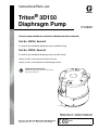
Instructions/Parts List
Triton® 3D150
Diaphragm Pump
311688D
Used to pump waterborne and solvent-based paints and catalysts.
Part No. 253704, Series B
3:1 Ratio Air-operated Double Diaphragm Pump, with BSPP Fittings
Part No. 253705, Series B
3:1 Ratio Air-operated Double Diaphragm Pump, with NPT Fittings
100 psi (0.7 MPa, 7 bar) Maximum Air Input Pressure
300 psi (2.1 MPa, 21 bar) Maximum Fluid Working Pressure
Important Safety Instructions
Read all warnings and instructions in this manual.
Save these instructions.
TI2125A
Graco Inc. P.O. Box 1441 Minneapolis, MN 55440-1441
Copyright 2006, Graco Inc. is registered to I.S. EN ISO 9001
II 2 G
Contents
Warning . . . . . . . . . . . . . . . . . . . . . . . . . . . . . . . . . . . 3
Installation . . . . . . . . . . . . . . . . . . . . . . . . . . . . . . . . 5
General Information . . . . . . . . . . . . . . . . . . . . . . 5
Tightening Threaded Fasteners Before First Use 5
Mounting the Pump . . . . . . . . . . . . . . . . . . . . . . . 6
Air Line . . . . . . . . . . . . . . . . . . . . . . . . . . . . . . . . 7
Fluid Suction Line . . . . . . . . . . . . . . . . . . . . . . . . 7
Fluid Outlet Line . . . . . . . . . . . . . . . . . . . . . . . . . 7
Grounding . . . . . . . . . . . . . . . . . . . . . . . . . . . . . . 9
Operation . . . . . . . . . . . . . . . . . . . . . . . . . . . . . . . . 10
Pressure Relief Procedure . . . . . . . . . . . . . . . . 10
Flushing the Pump Before First Use . . . . . . . . . 10
Starting and Adjusting the Pump . . . . . . . . . . . 10
Pump Shutdown . . . . . . . . . . . . . . . . . . . . . . . . 10
Maintenance . . . . . . . . . . . . . . . . . . . . . . . . . . . . . . 11
Lubrication . . . . . . . . . . . . . . . . . . . . . . . . . . . . 11
Flushing and Storage . . . . . . . . . . . . . . . . . . . . 11
Tightening Threaded Connections . . . . . . . . . . 11
Preventive Maintenance Schedule . . . . . . . . . . 11
2
Troubleshooting . . . . . . . . . . . . . . . . . . . . . . . . . . . 12
Repair . . . . . . . . . . . . . . . . . . . . . . . . . . . . . . . . . . . 13
Prepare the Pump for Repair . . . . . . . . . . . . . . . 13
General Repair Notes . . . . . . . . . . . . . . . . . . . . 13
Fault Indications . . . . . . . . . . . . . . . . . . . . . . . . 13
Tools Required . . . . . . . . . . . . . . . . . . . . . . . . . . 13
Replace the Diaphragms . . . . . . . . . . . . . . . . . . 14
Repair the Air Valve . . . . . . . . . . . . . . . . . . . . . . 16
Repair the Shaft and Bearings . . . . . . . . . . . . . 18
Replace the Ball Check Valves . . . . . . . . . . . . . 20
Parts . . . . . . . . . . . . . . . . . . . . . . . . . . . . . . . . . . . . 22
Technical Data . . . . . . . . . . . . . . . . . . . . . . . . . . . . 24
Performance Chart . . . . . . . . . . . . . . . . . . . . . . . . . 25
Dimensions . . . . . . . . . . . . . . . . . . . . . . . . . . . . . . . 26
Graco Standard Warranty . . . . . . . . . . . . . . . . . . . 28
Graco Information . . . . . . . . . . . . . . . . . . . . . . . . . 28
311688D
Warnings
Warnings
The following warnings are for the setup, use, grounding, maintenance, and repair of this equipment. The exclamation point symbol alerts you to a general warning and the hazard symbol refers to procedure-specific risk. Refer back
to these warnings. Additional, product-specific warnings may be found throughout the body of this manual where
applicable.
Warning
EQUIPMENT MISUSE HAZARD
Equipment misuse can cause the equipment to rupture or malfunction and result in serious injury.
•
•
•
•
•
•
•
•
•
•
•
This equipment is for professional use only.
Read all instruction manuals, tags, and labels before operating the equipment.
Use the equipment only for its intended purpose. If you are not sure, call your Graco distributor.
Do not alter or modify this equipment. Use only genuine Graco parts and accessories.
Check equipment daily. Repair or replace worn or damaged parts immediately.
Do not exceed the maximum working pressure of the lowest rated system component. Refer to the
Technical Data on page 24 for the maximum working pressure of this equipment.
Use fluids and solvents which are compatible with the equipment wetted parts. Refer to the Technical Data section of all equipment manuals. Read the fluid and solvent manufacturer's warnings.
Do not use hoses to pull equipment.
Route hoses away from traffic areas, sharp edges, moving parts, and hot surfaces. Do not expose
Graco hoses to temperatures above 82°C (180°F) or below -40°C (-40°F).
Wear hearing protection when operating this equipment.
Comply with all applicable local, state, and national fire, electrical, and safety regulations.
PRESSURIZED EQUIPMENT HAZARD
Spray from the gun, hose leaks, or ruptured components can splash fluid in the eyes or on the skin and
cause serious injury.
•
•
•
•
•
Do not point the gun at anyone or at any parts of the body.
Do not stop or deflect leaks with your hand, body, glove, or rag.
Follow the Pressure Relief Procedure on page 10 whenever you are instructed to relieve pressure;
stop spraying; clean, check, or repair the equipment; and install or clean the spray nozzle.
Tighten all fluid connections before operating the equipment.
Check the hoses, tubes, and couplings daily. Replace worn, damaged, or loose parts immediately.
Permanently coupled hoses cannot be repaired; replace the entire hose.
FIRE AND EXPLOSION HAZARD
Improper grounding, poor ventilation, open flames or sparks can cause a hazardous condition and result
in a fire or explosion and serious injury.
•
•
•
•
•
311688D
Ground the equipment and the object being sprayed. Refer to Grounding on page 9.
If there is any static sparking or you feel an electric shock while using this equipment, stop the
equipment immediately. Do not use the equipment until you identify and correct the problem.
Provide fresh air ventilation to avoid the buildup of flammable fumes from solvents or the fluid being
sprayed.
Keep the work area free of debris, including solvent, rags, and gasoline.
Eliminate all ignition sources such as pilot lights, cigarettes, and static arcs from plastic drop cloths.
Do not plug in or unplug power cords or turn lights on or off in the spray area.
3
Warnings
Warning
TOXIC FLUID HAZARD
Hazardous fluid or toxic fumes can cause serious injury or death if splashed in the eyes or on the skin,
inhaled, or swallowed.
•
•
•
•
Know the specific hazards of the fluid you are using.
Store hazardous fluid in an approved container. Dispose of hazardous fluid according to all local,
state and national guidelines.
Always wear protective eyewear, gloves, clothing and respirator as recommended by the fluid and
solvent manufacturer.
If a diaphragm fails, fluid is exhausted along with the air. When pumping hazardous fluids, place the
pump in an appropriate container to catch the fluid if a diaphragm ruptures.
MOVING PARTS HAZARD
Moving parts, such as the diaphragm shaft, can pinch or amputate your fingers.
•
Before servicing the equipment, follow the Pressure Relief Procedure on page 10 to prevent the
equipment from starting unexpectedly.
PERSONAL PROTECTIVE EQUIPMENT
You must wear appropriate protective equipment when operating, servicing, or when in the operating
area of the equipment to help protect you from serious injury, including eye injury, inhalation of toxic
fumes, burns, and hearing loss. This equipment includes but is not limited to:
• Protective eyewear
• Clothing and respirator as recommended by the fluid and solvent manufacturer
• Gloves
• Hearing protection
4
311688D
Installation
Installation
General Information
•
•
•
FIG. 2 is only a guide for installing system components and accessories. It is not an actual system
design. Contact your Graco distributor for assistance in designing a system to suit your particular
needs.
Always use Genuine Graco Parts and Accessories,
available from your Graco distributor. If you supply
your own accessories, be sure they are adequately
sized and pressure-rated for your system.
Tightening Threaded Fasteners
Before First Use
See the Repair section for torque specifications.
•
•
•
After unpacking the pump and before using it for the
first time, check and retorque all diaphragm cover
bolts (38, 39).
After the first day of operation, retorque the fasteners again.
As a general guidline, retorque fasteners every two
months.
Reference numbers and letters in parentheses refer
to the reference numbers in the figures and the
parts list on page 22.
311688D
5
Installation
Mounting the Pump
•
For ease of operation and service, mount the pump
so the air inlet, fluid inlet, and fluid outlet ports are
easily accessible.
•
Mount the pump in a well-ventilated area with sufficient clearance on all sides for operator access and
servicing.
•
The pump must be mounted horizontally as shown
in FIG. 1. Be sure that the pump is level in all directions and that the cylinder housing (54) is positioned
on the bottom. See FIG. 1.
•
The pump can be floor mounted or mounted on a
wall using mounting kit 246495.
•
Be sure the mounting can support the weight of the
pump, hoses, and accessories as well as the stress
caused during operation. The pump has two mounting holes for 0.31 in. (8 mm) screws. See the
Dimension drawing on page 26.
5. Mount the bracket with the pump attached to the
wall and tighten.
Hexagonal screw (2 required)
Compressed air
connection
Fluid
Inlet
Fluid
Outlet
Cylinder
Housing (54)
TI2133A 2
Floor Mount
Hexagonal
screw
(2 required)
Wall mount using kit 246495:
1. Use the bracket (15C022) as a template to drill 2
0.38 (9.6 mm) diameter holes in the wall.
Wall
Mount
Bracket
2. Loosely attach bracket (15C022) to the wall with
anchors and screws (8 mm) long enough to prevent
the bracket from vibrating during operation.
3. Remove bracket from the wall and fasten it to the
pump using the 4 screws (116899) and 1 lock
washer (100028) included in the kit.
4. The lock washer must be used in the unpainted hole
to ensure proper grounding of the bracket.
6
TI2469A
Wall Mount
FIG. 1. Mounting the Pump
311688D
Installation
Air Line
•
For maximum suction lift (wet and dry) information,
see Technical Data on page 24.
1. Install the air line accessories as shown in FIG. 2.
Be sure the air line supplying the accessories is
grounded.
•
Use an agitator to prevent fluid from settling out.
Part number 245081 Agitator Kit (accessory) is
available.
a. The fluid pressure can be controlled with either
an air regulator (F) to control the air into the
pump, or with a fluid regulator (H) to control the
fluid out of the pump.
b.
c.
Install a bleed-type master air valve (B) close to
the pump. This valve is required in your system
to relieve air trapped between it and the pump
when the valve is closed. Trapped air can cause
the pump to cycle unexpectedly which could
result in serious injury including splashing in the
eyes or on the skin, or injury from moving parts.
Be sure the bleed valve is easily accessible
from the pump, and is located downstream from
the air regulator.
Install a second air valve (E) upstream from all
air line accessories to isolate them during
cleaning and repair.
d. Install an air line filter (D) to remove contaminates such as dirt, moisture, and oil from the
compressed air supply.
Fluid Outlet Line
1. Use electrically conductive fluid hoses (P). See FIG.
2. Screw the fluid fitting into the pump outlet (N)
snugly while supporting the outlet with a wrench.
See Technical Data on page 24 to determine the
fluid outlet size of your pump.
2. Install a fluid regulator (H) at the pump fluid outlet to
control fluid pressure, if desired. See Air Line step
1a for an alternative method to control pressure.
3. Install a fluid drain valve (J) near the fluid outlet.
A fluid drain (J) valve is required in your system to
relieve pressure in the hose if it is plugged. The drain
valve reduces the risk of serious injury, including
splashing in the eyes or on the skin, or contamination
from hazardous fluids when relieving pressure. Install
the valve close to the pump fluid outlet. To use the
valve as a circulation valve, connect a tube (K)
between the valve and pail.
2. The air valve does not require lubrication.
3. Install a grounded, flexible air hose between the
accessories and the pump air inlet. See Technical
Data on page 24 to determine the air inlet size of
your pump. Use a minimum 1/2 in.(13 mm) ID air
hose.
Fluid Suction Line
•
See Technical Data on page 24 to determine the
fluid inlet size of your pump.
•
Use conductive hoses (see FIG. 2). Screw the suction line into the pump inlet snugly while supporting
the inlet with a wrench. Use a compatible liquid
thread sealant on connections to prevent air from
entering the fluid line.
311688D
CAUTION
Some systems may require installation of a pressure
relief valve at the pump outlet to prevent overpressurization and rupture of the pump or hose.
Thermal expansion of fluid in the outlet line can cause
overpressurization. This can occur when using long
fluid lines exposed to sunlight or ambient heat, or
when pumping from a cool to a warm area (for example, from an underground tank).
Overpressurization can also occur if the pump is
being used to feed fluid to a piston pump and the
intake valve of the piston pump does not close, causing fluid to back up in the outlet line.
7
Installation
Key:
A
B
C
D
E
F
G
H
J
K
L
M
N
P
R
S
T
U
W
TRITON 3D150 Pump
Bleed-type master air valve
(required for pump)
Air supply line
Air line filter
Air line shutoff valve
Pump air regulator
Gun air regulator (used in
spray system only)
Fluid pressure regulator
(used in spray system
only)
Drain/circulation valve
Drain tube
Suction tube
Pump fluid inlet
Pump fluid outlet
Fluid hose (shown
connected to gun in spray
system)
Gun air hose (used in
spray system only)
Spray gun (used in spray
system only)
Pump air inlet
Agitator (used in spray
system only)
Ground wire
S
R
G
B
C
T
J
H
E
F
D
P
W
M
L
A
K
N
TI2373A
T
K
J
W
L
U
M
A
N
H
TI2127A
FIG. 2. Typical Installation
8
311688D
Installation
Grounding
•
All fluid pails used when flushing: Follow your local
code. Use only conductive metal pails placed on a
grounded surface. Do not place the pail on a nonconductive surface, such as paper or cardboard,
which interrupts the grounding continuity.
Before operating the pump, ground the system as
explained below. Read the warnings on page 3.
Ground all of this equipment:
X
•
Pump: use a ground wire and clamp. See FIG. 3.
Loosen the grounding screw (X). Insert one end of a
12 ga (1.5 mm2) minimum ground wire (Y) under the
clamp and tighten the screw securely. Connect the
other end of the wire to a true earth ground. For a
ground wire and clamp, order Part No. 222011.
•
Air and fluid hoses: Use only electrically conductive
hoses.
•
Air compressor: Follow manufacturer’s recommendations.
•
Fluid supply drum: Follow your local code.
Y
TI2126A
311688D
FIG. 3. Grounding the Pump
9
Operation
Operation
Pressure Relief Procedure
4. Place the end of the fluid hose (P), see FIG. 2, into
an appropriate container.
5. Close the fluid drain valve (J).
6. With the pump air regulator (F) closed, open the
bleed-type master air valve (B).
Read the warnings on page 3, and follow the Pressure Relief procedure below whenever you:
•
•
•
•
are instructed to relieve pressure
stop spraying
check or service any of the equipment
install or clean the fluid nozzle.
1. Shut off the air to the pump.
2. Open the dispensing valve, if used.
3. Open the fluid drain valve to relieve all fluid pressure, having a container ready to catch the
drainage.
Flushing the Pump Before First
Use
The pump was tested in oil. If oil could contaminate the
fluid you are pumping, flush the pump thoroughly with a
compatible flushing fluid. Follow the steps under Starting and Adjusting the Pump.
Starting and Adjusting the Pump
1. Be sure the pump is properly grounded. Refer to
Grounding on page 9.
2. Check all fittings to be sure they are tight. Be sure to
use a compatible liquid thread sealant on all male
threads. Re-torque diaphragm cover bolts (38, 39)
before start-up.
7. If the fluid hose has a dispensing device, hold it
open while continuing with the following step.
8. Slowly open the air regulator (F) until the pump
starts to cycle. Allow the pump to cycle slowly until
all air is pushed out of the lines and the pump is
primed.
If you are flushing, run the pump long enough to thoroughly clean the pump and hoses. Close the air regulator. Remove the suction tube (L) from compatible
flushing fluid and place it in the fluid to be pumped.
Operating the pump dry for extended periods or
operating at pressures higher than the recommended maximum input air pressure will reduce
diaphragm life.
Pump Shutdown
Short Term Shutdown
For a short term shutdown, relieve the pressure (see
procedure on this page).
Long Term Shutdown
For a long term shutdown, such as several hours or
overnight:
1. Flush the pump thoroughly.
2. Leave compatible flushing fluid in the pump.
3. Place the suction tube (L) in the fluid to be pumped.
3. Relieve the pressure (see procedure on this page).
10
311688D
Maintenance
Maintenance
Lubrication
Tightening Threaded
Connections
CAUTION
Lubrication of the pump is not required. Oil is
exhausted through the muffler, which could contaminate the fluid supply or other equipment. Excessive
lubrication can also cause the pump to malfunction.
1. Before each use, check all hoses for wear or damage, and replace as necessary.
2. Check to be sure all threaded connections are tight
and leak-free.
Flushing and Storage
3. Check and re-torque all screws and fasteners at
least every two months.
Flush the pump often enough to prevent the fluid you
are pumping from curing, drying, or freezing in the pump
and damaging it. Follow the Pressure Relief Procedure
on page 10 before storing it for any length of time. Use a
compatible flushing fluid.
Preventive Maintenance
Schedule
•
311688D
Establish a preventive maintenance schedule,
based on the service history of the pump. This is
especially important for prevention of spills or leakage due to diaphragm failure.
11
Troubleshooting
Troubleshooting
Relieve the pressure (page 10) before checking or
servicing the equipment.
Problem
Check all possible problems and causes before
disassembling the pump.
Cause
Solution
Pump cycles at stall or fails to hold
pressure at stall.
Worn check valve balls (26), seats
(31), or ball guides (32).
Replace. See page 20.
Pump will not cycle, or cycles once
and stops.
Stuck or dirty air valve.
Disassemble and clean air valve. See
page 16. Use filtered air.
Check valve ball (26) severely worn
and wedged in seat (31).
Replace ball and seat. See page 20.
Check valve ball (26) wedged in seat Replace. See page 20. Do not
(31) due to overpressurization.
exceed the maximum fluid working
pressure, see page 24.
Clogged fluid dispensing valve.
Relieve pressure and clear valve.
Pinched hose line.
Check lines.
Clogged suction line.
Inspect; clear.
Sticky or leaking check valves.
Clean or replace balls (26) and seats
(31). See page 20.
Ruptured diaphragm (9).
Replace. See page 13.
Restricted exhaust.
Remove restriction.
Loose suction line.
Tighten.
Ruptured diaphragm (9).
Replace. See page 13.
Pump running irregularly. Stroke frequency dropping, coming to standstill.
Worn parts.
Replace worn parts. Check compressed air supply.
Icing caused by: compressed air too
moist, stroke frequency too high,
local temperature too low.
Remove ice by changing operating
conditions.
Air escapes continually.
Damaged air valve cup (15) or seat.
Replace damaged parts. See page
16.
Foreign matter inside pump.
Check air filter.
Worn check valve seats.
Replace. See page 20.
Pump operates erratically.
Air bubbles in fluid.
Pump does not start, or pressure
fluctuates.
Inlet strainer blocked, maximum suc- Clean strainer. Replace defective
tion exceeded, hose or seal defecparts.
tive.
Contaminated fluid. Pump installed or Check fluid supply. Follow installaoperated incorrectly.
tion and operation instructions in this
manual.
12
311688D
Repair
Repair
Prepare the Pump for Repair
Fault Indications
1. Flush the pump if possible, page 11.
During operation, check for indications of worn or damaged parts, such as:
2. Relieve the pressure, page 10.
3. Disconnect the air and fluid hoses.
4. Remove the pump from its mounting and take it to
the work bench.
General Repair Notes
•
A qualified technician should make all repairs.
•
Inspect and clean all parts thoroughly before
reassembly.
•
Use only genuine Graco replacement parts,
available from your Graco distributor.
•
Be careful not to damage sealing surfaces.
•
Replace all o-rings removed from the pump.
•
Follow all lubrication, torque, and repair notes
in the repair procedures.
•
311688D
•
major pressure fluctuations
•
change in the pump’s operating sound
•
irregular operation.
Always replace worn or damaged parts immediately to
prevent additional damage.
Tools Required
•
3, 4, and 6 mm allen wrenches
•
12, 19, and 22 mm open end wrenches
•
internal snap ring pliers
•
o-ring pick
•
needlenose pliers
•
vise with soft jaws
Do not use silicone or silicone-based grease.
13
Repair
Replace the Diaphragms
d. Grip the cylinder-side diaphragm firmly and
unscrew it from the rod by hand.
e. Install a new diaphragm (9*) firmly, by hand.
Wear gloves when removing or assembling the diaphragms to reduce the risk of cuts.
Diaphragm Repair Kit 246011 is available. Parts
included in the kit are marked, for example (9*).
For the best results, replace both diaphragms.
Always replace the ball check seals (29) whenever the fluid covers are removed. These seals
are included in each of the repair kits.
Disassembly
1. Prepare the pump for repair of the cylinder-side diaphragm.
a. Press on the cylinder-side diaphragm so that it
protrudes into the cylinder. This will fully extend
the diaphragm on the housing side.
b.
Install new ball check seals (29*).
c.
Replace the fluid cover and install the 6 screws.
Torque the screws to 16 N•m (12 ft-lb).
4. Repair the housing-side diaphragm.
a. Remove the 6 screws and the fluid cover from
the housing side.
a. Remove the 6 screws (39) and fluid cover (37)
from the housing side of the pump.
b.
Remove the ball check seals.
b.
Press on the exposed diaphragm (9) to fully
extend the cylinder-side diaphragm.
c.
c.
Replace the housing-side cover and tighten the
6 screws.
The exposed diaphragm should be in the fully
extended position (protruding out from the cylinder). If it is not, reassemble the cylinder-side
seals and cover and repeat step 3.
The housing-side cover must be reassembled
tightly enough to prevent the shaft from turning
when the cylinder-side diaphragm is loosened.
2. Repair the cylinder-side diaphragm.
a. Remove the 6 screws (38) and fluid cover (37)
from the cylinder side.
14
3. Prepare the pump for repair of the housing-side diaphragm.
b.
Remove the ball check seals (29).
c.
The exposed diaphragm should be in the fully
extended position (protruding out from the cylinder). If it is not, reassemble the cylinder-side
seals and cover and repeat step 1.
d. Grip the housing-side diaphragm firmly and
unscrew it from the rod by hand.
e. Install a new diaphragm (9*) firmly, by hand.
f.
Install new ball check seals (29*).
g. Replace the fluid cover and install the 6 screws
(39*). Torque the screws to 16 N•m (12 ft-lb).
Spare diaphragms should be stored in a cool, dry place
and be used within 8 months to prevent diaphragm failure due to material aging.
311688D
Repair
1
Torque to 16 N•m (12 ft-lb).
7
1
39
37
54
Housing Side 9*
29*†‡◆
Cylinder Side 9*
29*†‡◆
1
37
29*†‡◆
29*†‡◆
38
1
TI"
FIG. 4 Replace the Diaphragms
311688D
15
Repair
Repair the Air Valve
Air Valve Repair Kit 245066 is available. Parts
included in the kit are marked, for example (33†).
For the best results, use all parts in the kit.
Reassembly
Lubricate all o-rings when reassembling the
pump.
1. Assemble in reverse order.
Disassembly
1. Prepare the pump for repair, page 13.
2. Remove the air valve sheet metal cover (36) and felt
dampener (34).
3. Unscrew the cylinder screws (21).
Orient the new flat gasket (19) on the air valve
plate (16) so that the channels in the plate are
completely covered.
The hole in the air valve plate (16) aligns with the
arrow on the housing.
4. Remove the valve cover (20) with the flat gasket
(19†).
5. Use two screwdrivers to lift out the air valve plate
(16†) and replace o-rings (17†◆) and (18†◆).
Remove two o-rings (55).
6. Remove the air valve cup (15†).
7. Remove one retaining clip (14) with pliers DIN
5256C nominal size 12-25 diameter.
Align
8. Screw cylinder screw (21) into the plug (12) and pull
it out. Replace o-ring (13†◆).
9. Repeat steps 8 and 9 for clip and plug on opposite
side.
10. Reach into the housing and press out the carriage
(10).
11. Replace o-rings (11†◆).
16
2. Replace all parts with the new ones supplied in kit
245066.
Four profile seals (29) are provided in kit 245066
as in all 308HP kits. These seals need to be
replaced only if the fluid covers are removed.
311688D
Repair
1
1
Lubricate.
2
Torque to 3.1 N•m (28 in-lb)
3
Align arrow on housing with point on air valve plate.
13†◆ 14
12
14
15†
17†◆
1
1
1
18†◆
11†◆
10
11†◆
1
16†
3
19†◆
20
21 2
44
55
14
13†◆
12
1
34
36
ti2130B
FIG. 5. Repair the Air Valve
311688D
17
Repair
Repair the Shaft and Bearings
Parts marked with a (♦) are included in Shaft
repair kit 233841. For the best results, use all
parts in the repair kit.
Parts marked with a (❖) are included in Bearing
repair kit 15J647.
Disassembly
1. Remove the diaphragms. See page 13.
2. Disassemble the air valve. See page 16.
3. Remove the housing (54).
•
Sleeve clamp (6) is visible inside the air valve
cavity. Spread the sleeve clamp (6) with pliers
DIN 5254A, nominal size 19, and at the same
time, slide the shaft assembly (7) out from the
end where housing (54) was removed.
The valve carriage (5) will remain free inside the
diaphragm housing.
18
4. Remove clip (42) and bearing (3).
Reassembly
1. Replace o-ring (2) in bearing, lubricate internal
o-rings.
2. Install new bearing (3) and clip (42) inside housing
(54).
3. Insert shaft assembly (7) into diaphragm housing (1)
through the valve carriage, spreading the sleeve
clamp to allow full insertion. Be careful to release
sleeve clamp (6) in the correct location along the
shaft to engage it in all three grooves.
4. Reinstall the housing (54).
5. Replace o-rings on the carriage, air valve plate, and
plugs and reinstall the air valve section. (See page
16.)
6. Replace the diaphragms (page 13).
7. Replace the ball check seals (29) (page 20) and
reinstall the fluid covers.
311688D
Repair
1
Lubricate.
2
Torque to 12 ft-lb (16 N•m)
3
Align arrow on housing with point on air valve plate.
4
Torque to 28 in-lb (3.1 N•m)
1
◆✘
2 39
54
1 37
*9
42❖
❖3
†‡◆29
3❖
❖43
2◆❖
❖43
42❖
◆❖ 2
*9
29*†‡◆
37
1
5
6
1 †◆11
1 †◆11
15† 17†◆ 1
10
38 2
18†◆ 1
12
*†‡◆29
◆❖2
❖42
43❖
29*†‡◆
3❖
21 4
34
13†◆ 1
36
14
55
44
3 †16
4
†◆19
20
7◆
ti2131
FIG. 6. Repair the Shaft
311688D
19
Repair
Replace the Ball Check Valves
Ball Check Valve Repair Kit 245067 is available.
Parts included in the kit are marked with a (‡). For
the best results, use all parts in the kit.
Disassembly
1. Remove fluid covers (see page 13). Do not remove
housing (54).
2. Remove the inlet and outlet ball checks (26-32).
Note that the orientation of the inlet check parts is
different than the outlet check parts. (See FIG. 7.)
If the inlet seats (31) are difficult to remove, drive
them out from the opposite side using a brass rod
and hammer.
Reassembly
1. Reinstall the inlet and outlet ball checks on one side
of the pump. The inlet and outlet checks are assembled differently, install them exactly as shown in FIG.
7.
2. Install one fluid cover loosely to prevent the ball
checks from falling out.
Align the through holes in the housing with each
other and with the covers.
3. Turn the pump over and install the ball checks on
the opposite side, exactly as shown.
4. Reinstall the fluid covers. (See page 13.)
3. Replace all parts provided in Kit 245067.
20
311688D
Repair
1
Torque to 12 ft-lb (16 N•m)
2
Align
1
29‡
32‡
26‡
31‡
1
30‡✖
2
‡29
‡28
‡26
‡32
Inlet Ball
Checks
Outlet Ball
Checks
27
30‡✖
31‡
‡32
26‡
‡26
32‡
‡28
29‡
‡29
1
ti2128B
FIG. 7. Replace the Ball Check Valves
311688D
21
Parts
Parts
Part No. 253704, Series B
Part No. 253705, Series B
39
37
23
*9
54
29*†‡◆
40
24
32‡
25
❖42
26‡
31‡
30‡✖
◆❖2
43❖
❖42
45
41
35
5
22
33
3❖
*9
6
37
15†
†◆11
†◆13
◆❖2
3❖
43❖
55
12
38
1★
14
21
10
4
‡27
◆❖2
‡32
43❖
†◆17
3❖
❖42
‡26
7◆
‡28
†◆18
†16
†◆19
20
*†‡◆29
44
34
36
♦8
ti2132g
22
311688D
Parts
Part No. 253704 BSPP, Series B
Part No. 253705 NPT, Series B
Ref.
Part No.
No.
1
2
3
4
5
6
7
8
9
10
11
12
13
14
15
16
17
18
19
20
21
★
◆❖
❖
117158
197645
15A289
◆
◆
*
197649
†◆
197651
†◆
197653
†
†
†◆
†◆
†◆
197659
116474
22
23
24
25
26
27
28
29
30
31
32
33
117160
197661
197662
116475
‡
‡
‡
*†‡◆
‡✖
‡
‡
197670
311688D
Description
HOUSING, diaphragm
O-RING
BEARING
O-RING
CARRIAGE, valve
CLAMP, sleeve
SHAFT, pump, diaphragm
O-RING
DIAPHRAGM
CARRIAGE
O-RING
PLUG
O-RING
CLIP, id
CUP, air valve
PLATE, air valve
O-RING
O-RING
GASKET, flat
COVER, valve
SCREW, cap, socket head; M4x20
Torque to 3.1 N•m (2.3 ft-lb)
VALVE, safety
DAMPENER, noise
PLATE, screw
SCREW, cap, socket head; M4x12
BALL, matrix
SEAL, profile
SEAT, valve, outlet
SEAL, profile
O-RING
SEAT, valve, inlet
GUIDE, ball
DAMPENER, felt, side
Qty
1
3
3
1
1
1
1
1
2
1
2
2
2
2
1
1
2
1
1
1
4
1
1
1
2
4
2
2
4
2
2
4
1
Ref.
Part No.
No.
34
35
36
37
38
197671
15J372
15J574
15A282
117240
39
115264
40
15A286
198832
41
42
43
44
45
46▲
54
116343
❖
❖
116595
111307
188621
258001
Description
Qty
DAMPENER, felt, air inlet side
COVER, exhaust
COVER, sheet metal, air valve
COVER, fluid
SCREW, cap, socket head; M8x70
Torque to 12 N•m (8.8 ft-lb)
SCREW, cap, socket head; M8x16
Torque to 12 N•m (8.8 ft-lb)
ADAPTER, pump diaphragm, for
253704
ADAPTER, pump diaphragm, for
253705
CLAMP, grounding
CLIP, ID, C-spring
O-RING
SCREW, M4 button head
WASHER (used with #41, 116343)
LABEL, warning (not shown)
HOUSING, cylinder
1
1
1
2
6
6
1
1
1
3
3
2
1
1
1
★ Included in Diaphragm Housing Repair Kit. Order
Kit 261665 for 253704 pumps and 261666 for
253705 pumps.
◆ Included in Shaft Repair Kit 233841.
❖ Included in Bearing Repair Kit. Order Kit 15J647.
* Included in Diaphragm Repair Kit 246011.
† Included in Air Valve Repair Kit 245066.
‡ Included in Ball Check Valve Repair Kit 245067.
✖ Available in 10-pack kit 15D564.
▲ Replacement Warning labels, signs, tags, and cards
are available at no cost.
23
Technical Data
Technical Data
Category
Data
Maximum fluid working pressure
300 psi (2.1 MPa, 21 bar)
Maximum air input pressure
100 psi (0.7 MPa, 7 bar)
Ratio
3:1
Maximum permissible stroke frequency in cycles/min
20
Volume per cycle (double stroke)
5 oz/cycle (150 cc/cycle)
Operating temperature range
50-176°F (10-80°C)
Dry suction lift
5 ft (1.5 m)
Wet suction lift
21 ft (6.5 m)
Air inlet size
1/4 npt (253705); 3/8 BSPP (253704)
Fluid inlet size
3/4 npt (253705); M26x1.5 (253704)
Fluid outlet size
3/8 npt (253705); 3/8 BSPP (253704)
Weight (approximate)
28 lb (12.7 kg)
Wetted parts
stainless steel, acetal, fluorocarbon, PTFE, nylon
Sound Pressure Levels in dB(A) at 50 cpm (measured at 1 meter from unit)
24
Inlet Air Pressure
Sound Pressure
29 psi (0.2 MPa, 2.0 bar)
72
58 psi (0.4 MPa, 4.0 bar)
76
87 psi (0.6 MPa, 6.0 bar)
78
100 psi (0.7 MPa, 7.0 bar)
80
311688D
Performance Chart
Performance Chart
Triton performance test, 40, 70, 100 psi (.27, .48, .69 MPa; 2.7, 4.8, 6.9 bar)
Cycles per minute
70 psi (.48 MPa, 4.8 bar)
100 psi
70 psi
40 psi (.27 MPa, 2.7 bar)
40 psi
Air Flow in SCFM
Outlet Pressure in PSI
100 psi (.69 MPa, 6.9 bar)
Outlet Flow in gallons per minute
311688D
25
Dimensions
Dimensions
66 mm
(2.6 in.)
102 mm
(4.0 in.)
Fluid Outlet;
253705 3/8 npt
253704 3/8 BSPP
234 mm
(9.2 in.)
Air Inlet
253705 1/4 npt
253704 3/8 BSPP
9 mm (0.35 in.)
diameter
mounting holes
Fluid Inlet;
253705 3/4 npt
253704 M26x1.5
104 mm
(4.1 in.)
184 mm
(7.2 in.)
TI2133A 1
26
TI2133A 2
311688D
Dimensions
311688D
27
Graco Standard Warranty
Graco warrants all equipment referenced in this document which is manufactured by Graco and bearing its name to be free from defects in
material and workmanship on the date of sale to the original purchaser for use. With the exception of any special, extended, or limited warranty
published by Graco, Graco will, for a period of twelve months from the date of sale, repair or replace any part of the equipment determined by
Graco to be defective. This warranty applies only when the equipment is installed, operated and maintained in accordance with Graco’s written
recommendations.
This warranty does not cover, and Graco shall not be liable for general wear and tear, or any malfunction, damage or wear caused by faulty
installation, misapplication, abrasion, corrosion, inadequate or improper maintenance, negligence, accident, tampering, or substitution of
non-Graco component parts. Nor shall Graco be liable for malfunction, damage or wear caused by the incompatibility of Graco equipment with
structures, accessories, equipment or materials not supplied by Graco, or the improper design, manufacture, installation, operation or
maintenance of structures, accessories, equipment or materials not supplied by Graco.
This warranty is conditioned upon the prepaid return of the equipment claimed to be defective to an authorized Graco distributor for verification of
the claimed defect. If the claimed defect is verified, Graco will repair or replace free of charge any defective parts. The equipment will be returned
to the original purchaser transportation prepaid. If inspection of the equipment does not disclose any defect in material or workmanship, repairs will
be made at a reasonable charge, which charges may include the costs of parts, labor, and transportation.
THIS WARRANTY IS EXCLUSIVE, AND IS IN LIEU OF ANY OTHER WARRANTIES, EXPRESS OR IMPLIED, INCLUDING BUT NOT LIMITED
TO WARRANTY OF MERCHANTABILITY OR WARRANTY OF FITNESS FOR A PARTICULAR PURPOSE.
Graco’s sole obligation and buyer’s sole remedy for any breach of warranty shall be as set forth above. The buyer agrees that no other remedy
(including, but not limited to, incidental or consequential damages for lost profits, lost sales, injury to person or property, or any other incidental or
consequential loss) shall be available. Any action for breach of warranty must be brought within two (2) years of the date of sale.
GRACO MAKES NO WARRANTY, AND DISCLAIMS ALL IMPLIED WARRANTIES OF MERCHANTABILITY AND FITNESS FOR A
PARTICULAR PURPOSE, IN CONNECTION WITH ACCESSORIES, EQUIPMENT, MATERIALS OR COMPONENTS SOLD BUT NOT
MANUFACTURED BY GRACO. These items sold, but not manufactured by Graco (such as electric motors, switches, hose, etc.), are subject to
the warranty, if any, of their manufacturer. Graco will provide purchaser with reasonable assistance in making any claim for breach of these
warranties.
In no event will Graco be liable for indirect, incidental, special or consequential damages resulting from Graco supplying equipment hereunder, or
the furnishing, performance, or use of any products or other goods sold hereto, whether due to a breach of contract, breach of warranty, the
negligence of Graco, or otherwise.
FOR GRACO CANADA CUSTOMERS
The Parties acknowledge that they have required that the present document, as well as all documents, notices and legal proceedings entered into,
given or instituted pursuant hereto or relating directly or indirectly hereto, be drawn up in English. Les parties reconnaissent avoir convenu que la
rédaction du présente document sera en Anglais, ainsi que tous documents, avis et procédures judiciaires exécutés, donnés ou intentés, à la suite
de ou en rapport, directement ou indirectement, avec les procédures concernées.
Graco Information
TO PLACE AN ORDER, contact your Graco distributor, or call this number to identify the distributor closest to you:
1-800-328-0211 Toll Free
612-623-6921
612-378-3505 Fax
All written and visual data contained in this document reflects the latest product information available at the time of publication.
Graco reserves the right to make changes at any time without notice.
This manual contains English. MM 311688
Graco Headquarters: Minneapolis
International Offices: Belgium, China, Japan, Korea
GRACO INC. P.O. BOX 1441 MINNEAPOLIS, MN 55440-1441
www.graco.com
10/2006, Revised 10/2007