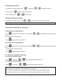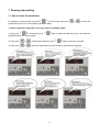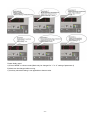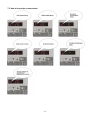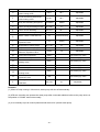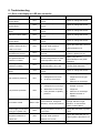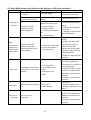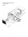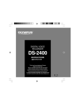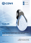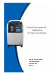
1
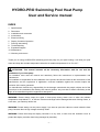
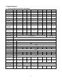
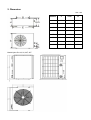
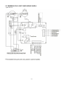
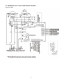
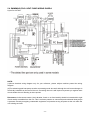
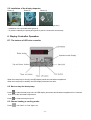
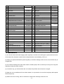
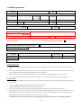
Swimming Pool Heat Pump
User and Service manual
English
●
French
●
Dutch
●
German
●
Russian
●
Polish
INDEX FOR DIFFERENT LANGUAGES
English manual………………………………........…………1~27
Manuel français………………………………..………..….28~54
Nederlandse handleiding……………………………..……55~81
Bedienungsanleitung Deutsch…………………………...82~108
инструкцию на русском……………….........................109~135
Polskiej firmy…………………….................……….......136~162
HYDRO-PRO Swimming Pool Heat Pump
User and Service manual
INDEX
1.
2.
3.
4.
5.
6.
7.
8.
9.
10.
11.
Specifications
Dimension
Installation and connection
Accessories
Electrical Wiring
Display Controller Operation
Running data setting
Troubleshooting
Exploded Diagram
Maintenance
Warranty and returns
Thank you for using HYDRO-PRO swimming pool heat pump for your pool heating, it will heat your pool
water and keep the constant temperature when the air ambient temperature is at -5 to 43℃
ATTENTION: This manual includes all the necessary information with the use and the
installation of your heat pump.
The installator must read the manual and attentively follow the instructions in implementation and
maintenance.
The installator is responsible for the installation of the product and should follow all the instructions of the
manufacturer and the regulations in application. Incorrect installation against the manual implies the
exclusion of the entire guarantee.
The manufacturer declines any responsibility for the damage caused with the people, objects and of the
errors due to the installation that disobey the manual guidline. Any use that is without conformity at the
origin of its manufacturing will be regarded as dangerous.
WARNING: Please always empty the water in heat pump during winter time or when the ambient
temperature drops below 0℃, or else the Titanium exchanger will be damaged because of being frozen, in
such case, your warranty will be lost.
WARNING: Please always cut the power supply if you want to open the cabinet to reach inside the heat
pump, because there is high voltage electricity inside.
WARNING: Please well keep the display controller in a dry area, or well close the insulation cover to
protect the display controller from being damaged by humidility.
-1-
1. Specifications
1.1 Technical data Hydro-Pro heat pumps
Unit Hydro-Pro
Part number
Heating capacity
A27/W27
Heating capacity
A15/W26
Cooling capacity
A35/W27
Power input
Maximum
volume(good
insulation)
Running current
Model
5
7008324
7
10
7008317 7008318
13
18
22
22T
26T
7008319
7008320
7008321
7008322
7008323
kW
5
7
10
13
18
22
22
26
BTU/h
17000
23500
34000
44300
61000
75000
75000
88700
kW
3,7
4,3
6,5
8,2
10,8
14,5
14,5
16,5
BTU/h
12500
14500
22000
28000
36000
49500
49500
56000
kW
2,8
3,5
5
7
9
11
11
15
BTU/h
9500
12000
17000
24000
30500
37500
37500
51000
kW
0,93
1,02
1,48
1,86
2,51
3,45
3,45
3,93
m³
20
30
45
60
85
120
120
140
A
4,1
4,7
7
9,1
11,4
15
6,6
7,7
Maximum
current
A
4,9
5,6
8,4
11
13,7
18
8,4
10
COP at A27/W27
W/W
5,8
5,9
6,2
6
6,1
5,9
5,9
5,8
COP at A15/W26
W/W
V/Ph/H
z
4
4,2
4,4
4,4
4,3
4,2
4,2
4,2
Power supply
220-240/1/50
380/3/50
Controller
Electronic
Condenser
Compressor
quantity
Compressor type
Titanium heat exchanger
1
Rotary
Scroll
Refrigerant
R410a
Fan quantity
1
Fan power input
W
Fan speed
RPM
68
80
80
120
200
400
400
400
830~870
Air Flow
Horizontal
Vertical
Noise level (10m)
dB(A)
39
40
40
43
44
47
47
50
Noise level (1m)
Water
connection
Nominal water
flow
dB(A)
48
49
49
52
53
56
56
59
mm
50
m³/h
2,5
2,5
2,8
3,5
4,6
6,2
6,2
7,1
kPa
12
12
12
15
16
18
18
18
Net dimensions
Shipping
dimensions
L/W/H
750*290*500
930*350*550
1000*360*620
865*685*910
L/W/H
850*330*540
1060*380*590
1120*380*660
885*740*1050
Net/gross weight
Kg
36/38
Maximum
pressure loss
44/47
49/52
63/67
* Above data are subjects to modification without notice.
-2-
100/110
125/135
125/135
150/160
2. Dimension
Unit : mm
Model Hydro Pro 18, 22, 22T, 26T
-3-
Models
5
7&10
13
A
273
330
330
B
423
680
655
C
260
280
300
D
293
360
360
E
747
930
1000
F
210
230
340
G
83
83
83
H
470
520
590
3. Installation and connection
3.1 Notes
The factory supplies only the heat pump. All other components, including a bypass if necessary, must be
provided by the user or the installer.
Attention:
Please observe the following rules when installing the heat pump:
1. Any addition of chemicals must take place in the piping located downstream from the heat pump.
2. Install a bypass if the water flow from the swimming pool pump is more than 20% greater than the
allowable flow through the heat exchanger of the heat pump.
3. Install the heat pump above the water level of the swimming pool.
4. Always place the heat pump on a solid foundation and use the included rubber mounts to avoid
vibration and noise.
5. Always hold the heat pump upright. If the unit has been held at an angle, wait at least 24 hours
before starting the heat pump.
3.2 Heat pump location
The unit will work properly in any desired location as long as the following three items are present:
1. Fresh air
–
2. Electricity
–
3. Swimming pool filters
The unit may be installed in virtually any outdoor location as long as the specified minimum distances to
other objects are maintained (see drawing below). Please consult your installer for installation with an
indoor pool. Installation in a windy location does not present any problem at all, unlike the situation with a
gas heater (including pilot flame problems).
ATTENTION: Never install the unit in a closed room with a limited air volume in which the air expelled from
the unit will be reused, or close to shrubbery that could block the air inlet. Such locations impair the
continuous supply of fresh air, resulting in reduced efficiency and possibly preventing sufficient heat output.
See the drawing below for minimum dimensions.
-4-
3.3 Distance from your swimming pool
The heat pump is normally installed within a perimeter area extending 7.5 m from the swimming pool. The
greater the distance from the pool, the greater the heat loss in the pipes. As the pipes are mostly
underground, the heat loss is low for distances up to 30 m (15 m from and to the pump; 30 m in total)
unless the ground is wet or the groundwater level is high. A rough estimate of the heat loss per 30 m is
0.6 kWh (2,000 BTU) for every 5 ºC difference between the water temperature in the pool and the
temperature of the soil surrounding the pipe. This increases the operating time by 3% to 5%.
3.4 Check-valve installation
Note: If automatic dosing equipment for chlorine and acidity (pH) is used, it is essential to protect the heat
pump against excessively high chemical concentrations which may corrode the heat exchanger. For this
reason, equipment of this sort must always be fitted in the piping on the downstream side of the heat
pump, and it is recommended to install a check-valve to prevent reverse flow in the absence of water
circulation.
Damage to the heat pump caused by failure to observe this instruction is not covered by the warranty.
-5-
3.5 Typical arrangement
Note: This arrangement is only an illustrative example.
3.6 Adjusting the bypass
Use the following procedure to adjust
the bypass:
To pool
•
fully open all three valves
•
slowly close valve 1 until the
water pressure is increased by
From pool
approximately 100 to 200 g
•
Close valve 3 approximately
half-way to adjust the gas
pressure in the cooling system
•
If the display shows "ON" or
error code EE3, close step by
Out
In
step the valve 2, to increase
water flow and stop when the
Heat Pump
code disappear.
Optimal operation of the heat pump occurs when the cooling gas pressure is 22 ±2 bar.
This pressure can be read on the pressure gauge next to the control heat pump panel. Under these
conditions the water flow through the unit is also optimal.
Note: Operation without a bypass or with improper bypass adjustment may result in sub-optimal
heat pump operation and possibly damage to the heat pump, which renders the warranty null and
void.
-6-
3.7 Electrical connection
Note: Although the heat pump is electrically isolated from the rest of the swimming pool system,
this only prevents the flow of electrical current to or from the water in the pool. Earthing is still
required for protection against short-circuits inside the unit. Always provide a good earth
connection.
Before connecting the unit, verify that the supply voltage matches the operating voltage of the heat pump.
It is recommended to connect the heat pump to a circuit with its own fuse or circuit breaker (slow type;
curve D) and to use adequate wiring (see table below).
For horizontal models (Hydro Pro7, 10, 13 and 18): remove the panel to the right of the fan opening.
(Hydro Pro 5: remove the top panel).
For vertical models (Hydro-Pro22, 22T and 26T): remove the corner panel with the electronic control panel.
Connect the electrical wires to the terminal block marked ‘ POWER SUPPLY ’.
A second terminal block marked ‘WATER PUMP ’ is located next to the first one. The filter pump (max. 5 A /
240 V) can be connected to the second terminal block here. This allows the filter pump operation to be
controlled by the heat pump.
Note: In the case of three-phase models, swapping two phases may cause the electric motors to run in the
reverse direction, which can lead to damage. For this reason, the unit has a built-in protective device that
breaks the circuit if the connection is not correct. If the red LED above this safety device lights up, you
must swap the connections of two of the phase wires.
Model
Voltage (V)
Fuse or
circuit
breaker (A)
Rated current (A)
Wire diameter mm2
(with max. 15 m length)
HYDRO PRO7
220–240
16
6.6
2x 1.5 + 1.5
HYDRO PRO10
220–240
16
9.2
2x 2.5 + 2.5
HYDRO PRO13
220–240
20
12.1
2x 2.5 + 2.5
HYDRO PRO18
220–240
25
16.5
2x 6 + 6
HYDRO PRO22
220–240
32
20.9
2x 6 + 6
HYDRO PRO22T
3x 380
20
7.9
4x 2.5 + 2.5
HYDRO PRO26T
3x 380
20
8.9
4x 2.5 + 2.5
-7-
3.8 Initial operation
Note: In order to heat the water in the pool (or hot tub), the filter pump must be running to cause the
water to circulate through the heat pump. The heat pump will not start up if the water is not
circulating.
After all connections have been made and checked, carry out the following procedure:
1. Switch on the filter pump. Check for leaks and verify that water is flowing from and to the swimming
pool.
2. Connect power to the heat pump and press the On/Off button
on the electronic control panel. The
unit will start up after the time delay expires (see below).
3. After a few minutes, check whether the air blowing out of the unit is cooler.
4. When turn off the filter pump , the unit should also turn off automatically , if not, then adjust the flow
switch.
5. Allow the heat pump and the filter pump to run 24 hours a day until the desired water temperature is
reached. The heat pump will stop running at this point. After this, it will restart automatically (as long as
the filter pump is running) whenever the swimming pool water temperature drops 2 degree below the
set temperature.
Depending on the initial temperature of the water in the swimming pool and the air temperature, it may take
several days to heat the water to the desired temperature. A good swimming pool cover can dramatically
reduce the required length of time.
Water Flow Switch:
It is equipped with a flow switch for protecting the HP unit running with adequate water flow rate .It will turn
on when the pool pump runs and shut it off when the pump shuts off. If the pool water level higher than 1
m above or below the heat pump’s automatic adjustment knob, your dealer may need to adjust its initial
startup.
Time delay - The heat pump has a built-in 3-minute start-up delay to protect the circuitry and avoid
excessive contact wear. The unit will restart automatically after this time delay expires. Even a brief power
interruption will trigger this time delay and prevent the unit from restarting immediately. Additional power
interruptions during this delay period do not affect the 3-minute duration of the delay.
3.9 Condensation
The air drawn into the heat pump is strongly cooled by the operation of the heat pump for heating the pool
water, which may cause condensation on the fins of the evaporator. The amount of condensation may be
as much as several litres per hour at high relative humidity. This is sometimes mistakenly regarded as a
water leak.
-8-
4. Accessories
4.1 Accessories list
Anti-vibration base, 4 pcs
Draining jet, 2 pcs
Waterproof box, 1 pc
10M Signal wire, 1 pc
Water drainage pipes, 2 pcs
4.2 Accessories Installation
Anti-vibration bases
1. Take out 4 Anti-vibration bases
2. Put them one by one on the bottom
of machine like the picture.
Draining jet
1. Install the draining jet under the
bottom panel
2. Connect with a water pipe to drain
out the water.
Note: Lift the heat pump to install the
jet. Never overturn the heat pump, it
could damage the compressor.
-9-
Water Inlet & outlet junction
1. Use the pipe tape to connect the
water Inlet & outlet junction onto the
heat pump
2. Install the two joints like the picture
shows
3. Screw them onto the water Inlet &
outlet junction
10M Signal wiring
1. Take one side of the 10M Signal
wire, to connect with the controller.
2. The other side needs to be pulled
through the hole, like the third picture
shows.
3. Then connect to the PC board
inside the machine : the brown one --first joint; the blue one --- second joint;
the yellow one --- third joint.
Cable wiring
1. Connect the power supply wire
through the white hole like the picture
shows.
2. Fix the other side on joints inside
the electric box.
Water pump wiring
1. Connect the water pump wire
through the white hole marked
2. Fix the other side on joints inside
the electric box.
- 10 -
5. Electrical Wiring
5.1 SWIMMING POOL HEAT PUMP WIRING DIADRA
Hydro Pro 5/7/10
- 11 -
5.2 SWIMMING POOL HEAT PUMP WIRING DIADRA
Hydro Pro 13
- 12 -
5.3 SWIMMING POOL HEAT PUMP WIRING DIADRA
Hydro Pro 18/22
- 13 -
5.4 SWIMMING POOL HEAT PUMP WIRING DIADRA
Hydro Pro 22T/26T
NOTE:
(1)Above electrical wiring diagram only for your reference, please subject machine posted the wiring
diagram.
(2)The swimming pool heat pump must be connected ground wire well, although the unit heat exchanger is
electrically isolated from the rest of the unit .Grounding the unit is still required to protect you against short
circuits inside the unit .Bonding is also required.
Disconnect: A disconnect means (circuit breaker, fused or un-fused switch) should be located within sight
of and readily accessible from the unit .This is common practice on commercial and residential heat pumps.
It prevents remotely-energizing unattended equipment and permits turning off power at the unit while the
unit is being serviced.
- 14 -
5.5 Installation of the display deportee
Photo (1)
Photo (2)
Photo (3)
- Disassembling of and degrafage control board of the connector (photo1)
- Installation of the provided cable (photo 2)
- To pass the cable by the press pack (photo 3) and to connect the sons directly
6. Display Controller Operation
6.1 The buttons of LED wire controller
When the heat pump is running, the LED display shows the inlet water temperature.
When the heat pump is standby, the LED display shows the real time.
6.2 Start or stop the heat pump.
Press
to start the heat pump unit, the LED display shows the desired water temperature for 5 seconds,
then shows the inlet water temperature.
Press
to stop the heat pump unit.
6.3 Choose heating or cooling mode:
Press
until “heat” or “Cool” light is on.
- 15 -
6.4 Setting the real time
On standby or running mode, press
Then press the
When setting the time,
, then press
or
to adjust hour/minute.
again to store the new data.
and
cannot work.
6.5 Water temperature setting:
On standby or running mode, press
and
to adjust the desired water temperature
Note : the heat pump can running only if the water circle/filtration system is running.
6.6 Automatic start/stop the heat pump
To set the time to start the unit
Press
to set the time to start the unit, then press
or
to adjust the time (set the time for
or
to adjust the time (set the time for
start
5 minutes after the water pump).
Press
again to store the new data.
To set the time to stop the unit
Press
to set the time to stop running, then press
stop
5 minutes before the water pump).
Press
again to store the new data.
6.7 Concell the automatic start/stop
To concell the automatic starter
Press
, then press
,
To concell the automatic starter
Press
, then press
light off and the automatic start is off.
,
light off and the automatic stop is off.
Note : If the water filtration system is stop before the heat pump, the unit will shut down (security
condition) and the code EE3 or ON advertise on the controller.
It is important to program the heat pump link the time program of the water filtration system.
For restart the heat pump, turn off and turn on the electrical power supply to restart the unit.
- 16 -
7. Running data setting
7.1 How to check the parameters
On standby or running mode, long press
for 10 seconds, then press
parameters (from 0 to H, see operation parameter table).
or
to check the
7.2 How to adjust the parameters (Can only adjust on standby mode)
1) Long press
for 10 seconds, press
parameter table) you want to adjust.
again to select the data (from 0 to L, see operation
2) Then press
or
to adjust the parameter, press
3) Then press
or
select the other datas you want to adjust, repeat above operation.
- 17 -
again to store the new data.
Please kindly noted:
A) Press “MODE” to choose mode (Mode only be changed for “1” or “2” setting of parameter 6)
B) Mode can be changed while running
C) Auxiliary electrical heating is not applicable to these modes.
- 18 -
7.3 How to know the current status
- 19 -
Parameter
0
1
Meaning
To set the entering water temp.
under cooling mode
To set the entering water temp.
under heating mode
Range
Default
Remarks
8-35℃
28℃
Adjustable
15-40℃
28℃
Adjustable
2
Entry into defrosting time period
30-90MIN
40MIN
Adjustable
3
Terms of Entry defrosting function
-30℃to0℃
-7℃
Adjustable
4
5
Terms of Exit defrosting
2 to 30℃
20℃
Adjustable
1 to 12MIN
12MIN
Adjustable
6
Mode: 0 Heat 1 Heat and Cool
0-1
1(Heat and Cool)
Adjustable
0-1
1(auto)
Adjustable
Superheat for heating target
-15℃-15℃
3℃
Adjustable
Superheat for cooling target
-15℃-15℃
-2 ℃
Adjustable
18-94
70
Adjustable
7
8
9
A
B
C
D
E
F
G
H
L
Time of Exit defrosting
Mode selection of Electronic
expansion valve
Manual adjustment steps of
electronic expansion valve
Inlet water temperature
-9-99℃
Exact testing by value
Outlet water temperature
-9-99℃
Exact testing by value
-9-99℃
Exact testing by value
Gas return temperature
-9-99℃
Exact testing by value
Ambient temperature
-9-99℃
Exact testing by value
-9-99℃
Exact testing by value
N*5
Exact testing by value
Condenser temperature under
heating mode
Condenser temperature under
Cooling mode
Actual steps of electronic
expansion valve
Entering water temperature
calibration
-9.9-9.9℃
0℃
Adjustable
Remarks:
(1) When HP stop running in 30 seconds, water pump will shut off automatically
(2) LED wire controller can operate the water pump after connected additional cable to the pump device in
the position of “PUMP” terminal accurately.
(3) It is necessary to put an extra 3-phase transfer device for 3 phase water pump.
- 20 -
8. Troubleshooting
8.1 Error code display on LED wire controller
Malfunction
Inlet water temperature
sensor failure
Outlet water temperature
sensor failure
Heating condenser sensor
failure
Gas return sensor failure
Ambient temperature
sensor failure
Error code
PP1
PP2
PP3
PP4
PP5
Temperature difference
between water inlet and
temperature is too low
First grade antifreeze
protection in Winter
Second grade antifreeze
protection in Winter
Cooling condenser sensor
failure
Solution
The sensor in open or short
circuit
The sensor in open or short
circuit
The sensor in open or short
circuit
The sensor in open or short
circuit
The sensor in open or short
circuit
Water flow volume not
PP6
outlet is too much
Cooling outlet water
Reason
enough ,water pressure
difference is too low
PP7
PP7
PP7
PP8
Check or change the sensor
Check or change the sensor
Check or change the sensor
Check or change the sensor
Check or change the sensor
Check the water flow volume or
water jammed or not
Water flow volume is not
Check the water flow or water
enough
system is jammed or not
Ambient temperature or water
inlet temperature is too low
Water pump will run
automatically for first grade
antifreeze
Ambient temperature or water
Heat pump will start heating for
inlet temperature is too low
second grade antifreeze
The sensor in open or short
circuit
Check or change the sensor
1. Discharge redundant
High pressure protection
EE1
1. Refrigerant is too much
refrigerant from HP gas
2. Air flow is not enough
system
2. Clean the air exchanger
1. Check if there is any gas
Low pressure protection
EE2
1. Refrigerant is not enough
leakage ,re-fill the
2. Water flow is not enough
refrigerant
3. Filter jammed or capillary
jammed
2. Clean the air exchanger
3. Replace the filter or
capillary
Check if the water flow is
Flow switch closed
EE3 or "ON"
Low water flow, wrong flow
enough and flow in right
direction, or flow switch failure.
direction, or else the flow
switch could be failed.
Power supply connections
wrong (for 3 phase unit)
EE4
Inlet and outlet water
temperature difference
Check the connection of power
connection
cable
Water flow volume is not
EE5
malfunction
Communication failure
Wrong connection or lack of
enough ,water pressure
difference is too low
EE8
Wire connection is not good
- 21 -
Check the water flow rate ,or
water system is jammed or not
Check the wire connection
8.2 Other Malfunctions and Solutions (No display on LED wire controller)
Malfunctions
Observing
LED wire controller
no display.
No power supply
LED wire controller.
Heat pump under standby
displays the actual time.
status
1. Water temperature is
Heat pump is
not running
Reasons
reaching to setting value,
LED wire controller
HP under constant
displays the actual
temperature status.
water temperature.
2. Heat pump just starts to
run.
3. Under defrosting.
Solution
Check cable and circuit
breaker if it is connected
Startup heat pump to run.
1. Verify water temperature
setting.
2. Startup heat pump after a
few minutes.
3. LED wire controller should
display "Defrosting".
1. Adjust the mode to proper
running
Water
temperature is
cooling when
HP runs under
heating mode
2. Replace the defect LED
LED wire controller
displays actual water
temperature and no error
code displays.
1. Choose the wrong mode.
2. Figures show defects.
3. Controller defect.
wire controller, and then
check the status after
changing the running mode,
verifying the water inlet and
outlet temperature.
3. Replace or repair the heat
pump unit
1. Check the cable
connections between the
1. Fan NO running.
Short running
LED displays actual water
2. Air ventilation is not
temperature, no error code
enough.
displays.
3. Refrigerant is not
enough.
motor and fan, if necessary, it
should be replaced.
2. Check the location of heat
pump unit, and eliminate all
obstacles to make good air
ventilation.
3 Replace or repair the heat
pump unit.
1. No action.
water stains
Water stains on heat pump
1. Concreting.
2. Check the titanium heat
unit.
2. Water leakage.
exchanger carefully if it is any
defect.
1. Check the location of heat
pump unit, and eliminate all
Too much ice
Too much ice on
obstacles to make good air
on evaporator
evaporator.
ventilation.
2. Replace or repair the heat
pump unit.
- 22 -
9. Exploded Diagram and Maintenance
9. 1 Exploded Diagram
Model 5 kw
- 23 -
NO
Part Name
1
Front grill
2
Front panel
3
Fan blade
4
Fan motor
5
ERP code
NO
Part Name
ERP code
28
Pipes temperature sensor collet
111900004
29
Pipes temperature sensor
111900004
113600017
30
Back grill
11140053
31
Ambient temperature sensor
112200141
Fan motor bracket
1110130030
32
Ambient temperature sensor clip
113715001
6
maintain board
1110210031
33
Top cover
7
Base tray
1110160102
34
Compressor wiring clip
110100038
8
Compressor
110100038
35
Water flow switch
112100021
9
Temperature sensor of water-in
112200133
36
isolation panel
1110110027
10
Titanium heat exchanger
113900077
37
controller box
11
Panel on the side
1110021029
38
Cable fixing clamp-up
12
Drainage hole plug
113700077
39
Cable fixing clamp-down
13
Suction valve
112500019
40
Terminal blocks
14
Cable joints
114000184
41
controller box cover
15
Pressure guage
110800001
42
PC board
16
Controller
112200149
43
Capacitance clamp
17
Waterproof box
113712001
44
Capacitance
111300014
18
Panel on the side
1110021029
45
Transformator
112200064
19
Water inlet/outlet bolt
114000015
46
Fan motor capacitance
111300002
20
Suction pipe
1117991662
47
Pillar
1110070043
21
Exhaust pipe
1117991662
48
Grill on the side
1110090019
22
Pipe (4 way valve to evaporator)
1117991662
49
4 way valve
23
Pipe (4 way valve to heat
exchanger)
1117991662
50
Pipe (heat exchanger to capillary)
1117991644
24
Water inlet/outlet screw cap
113900052
51
Liquid separator
1117991644
25
Capillary
1117991662
52
low pressure protection switch
112100003
26
Collection pipes
1117991662
53
high pressure protection switch
112100011
27
Evaporator
1110040024
1110080042
1110030042
1110120146
113500007
112000008
1110150036
11220183
1110220010
112600001
Z1Z08Y313
10. Maintenance
(1) You should check the water supply system regularly to avoid the air entering the system and occurrence
of low water flow, because it would reduce the performance and reliability of HP unit.
(2) Clean your pools and filtration system regularly to avoid the damage of the unit as a result of the dirty of
clogged filter.
(3) You should discharge the water from bottom of water pump if HP unit will stop running for a long time
(specially during the winter season).
(4) In another way, you should check the unit is water fully before the unit start to run again.
(5) After the unit is conditioned for the winter season, he is preconize to cover the heat pump with special
winter heat pump.
(6) When the unit is running, there is all the time a little water discharge under the unit.
- 24 -
11. Warranty and returns
11.1 Warranty
LIMITED WARRANTY
Thank you for purchasing a heat pump from us.
This warranty covers manufacturing and material defects in all components for a period of two years after the
date of purchase.
This warranty is limited to the original purchaser in the retail sector. It is not transferable, and it is not applicable
to products that have been removed from their original installation location. The liability of the manufacturer is
limited to the repair or replacement of defective components and does not include the cost of labour for
removing and replacing the defective component(s), the cost of transporting component(s) from or to the
factory, or costs associated with other materials necessary for carrying out repairs. This warranty does not cover
any defects attributable to the following causes:
1.
Installation, operation or maintenance of the product other than in accordance with the guidelines
and/or instructions in the Installation and Operation Manual supplied with the product.
2.
Faulty or deficient work performed on the product by an installer.
3.
Failure to maintain the correct chemical balance in the swimming pool [pH between 7.0 and 7.8; total
alkalinity (TA) between 80 and 150 ppm; free chlorine concentration between 0.5 and 1.2 mg/l; total
dissolved solids (TDS) less than 1,200 ppm; maximum salt concentration 8 g/l].
4.
Improper use, modification, accident, fire, flood, lighting strike, rodents, insects, negligence, neglect, or
force majeure.
5.
Deposits, freezing, or other conditions that impair proper water flow through the product.
6.
Operating the product with a flow rate outside the published minimum and maximum specifications.
7.
Use of components or accessories not designed or made for this product.
8.
Chemical contamination of the air used by the product or improper use of decontaminating chemicals,
such as the addition of decontaminating chemicals through the skimmer or in the pipes or lines located upstream
of the heat pump and the cleaning hose.
9.
Overheating, improper electrical connections, improper power supply, secondary damage attributable to
defective O-rings, diatomaceous filters or filter cartridges, or damage caused by putting the pump into operation
in the absence of sufficient water.
LIMITATIONS ON LIABILITY
This is the sole warranty provided by the manufacturer. Nobody is authorised to grant other warranties in our
name.
THIS WARRANTY REPLACES ALL OTHER EXPLICITLY GRANTED OR IMPLICIT
WARRANTIES, INCLUDING BUT NOT LIMITED TO ANY FORM OF IMPLICIT WARRANTY OF
SUITABILITY FOR A PARTICULAR PURPOSE OR FITNESS FOR SALE. WE EXPLICITLY
DISAVOW ANY LIABILITY FOR INDIRECT, INCIDENTAL OR CONSEQUENTIAL LOSS OR
DAMAGE OF A PUNITIVE NATURE RESULTING FROM THE VIOLATION OF AN EXPLICITLY
GRANTED OR IMPLICIT WARRANTY.
This warranty gives you specific legal rights, which may vary depending on the country.
WARRANTY CLAIMS
To ensure prompt handling of your warranty claim, please contact your dealer and provide the following
information to the dealer: proof of purchase, model number, serial number and date of installation. The installer
will contact the factory to obtain instructions regarding the procedure for making warranty claims and to find
out the location of the closest service centre.
All returned components must be marked with a RMA number so that it can be determined whether they are
covered by the warranty.
- 25 -
11.2 RMA request form
Date:
Company:
Street address:
City/town:
Postal
code:
Country:
Contact:
Phone:
Fax:
E-mail:
Contact:
Date:
Reserved for internal use
RMA no.:
Assigned by:
Reason for return:
Date:
Copy of customer invoice included?
RMA request accompanied by other documents?
Description of the documents:
Invoice no.:
Invoice date:
Model no.:
Serial number:
Problem:
Warranty repair policy
1.
Shipping costs for returned products must be paid in advance. All shipping costs associated with a return shipment are borne by
you.
2.
Products may be sent back to us only after prior approval by the company. Return shipments for which approval has not been given
by the company will be sent back, with all shipping costs to be borne by you.
3.
We will replace or repair the products and return them to you free of charge using the shipping service of your choice.
4.
If you choose express shipment (by a shipping service selected by you), you are responsible for paying the shipping costs.
Return procedure
1.
Before requesting an RMA number from us, please check whether you have properly observed the installation and use instructions
in the manual.
2.
Contact our RMA department by phone and ask for an RMA request form.
3.
Ensure that all fields of the RMA request form are fully completed.
4.
In the case of returns during the warranty period, please include the customer copy of your original sales invoice.
5.
Send the RMA request form, the sales invoice and any other relevant documents (photos, etc.) to us or provide them by e-mail. An
RMA number will be assigned to you within 24 hours after we receive the necessary documents. We may refuse to assign you an
RMA number if the information mentioned in points 3 and 4 above is missing.
6.
The RMA number must be marked clearly on the shipping label of the package and noted on the shipping documents.
- 26 -
7.
All products received by us that lack labels or that have incorrect, incomplete or unreadable labels will be refused, with return
shipping costs to be borne by you.
8.
All packages delivered to us with clearly visible damage will be refused immediately.
9.
Before returning products, please check that the products you intend to return to us are the same as the products for which an RMA
number was issued. If the received products do not match the products registered under the assigned RMA number, we will return
all of the products at your expense.
10. No return shipments at all will be accepted without an RMA number. Absolutely no exceptions to this rule are allowed.
11. An RMA number remains valid for just 21 calendar days after it is assigned. We reserve the right to refuse to accept
products returned to us if they are received more than 21 days after the date when the RMA number was assigned.
Products not covered or no longer covered by the warranty
The customer is responsible for paying shipping and repair costs The estimated repair costs will be advised after the
problem(s) with the returned products have been diagnosed.
The minimum charge of a diagnosis is €50.00.
MegaGroup Trade Holding BV
Doornhoek 4205 – 5465 TG Veghel – The Netherlands
P.O. Box 430 – 5460 AK Veghel
– The Netherlands
T: +31 413 747 300
www.megagrouptrade.com – [email protected]
- 27 -