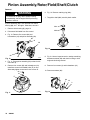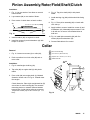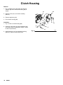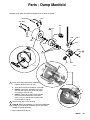
1
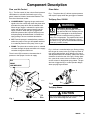
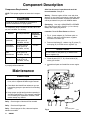
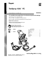
Repair
TexSpray 1030t FC
309662J
German Patent No. P 43 18 679.3--09
- For portable spray application of architectural paints and coatings 0.9 to 3.0 gpm (3.4 to 11.4 lpm) Flow Rate
750 psi (5.1 MPa, 51 bar) Maximum Working Pressure
500 psi (3.4 MPa, 34 bar) Recommended Maximum Working Pressure
Model 234113, Series A
TexSpray 1030 FC sprayer, 235490 TexSpray gun
and 50 ft (15 m) air and fluid hose set
Important Safety Instructions
Read all warnings and instructions in this
manual. Save these instructions.
CONTENTS
. . . . . . . 309663
. . . . . . . 308274
‘
Warnings . . . . . . . . . . . . . . . . . . . . . . . . . . . . . . 2
Component Description . . . . . . . . . . . . . . . . . . 5
Maintenance . . . . . . . . . . . . . . . . . . . . . . . . . . . 6
Troubleshooting . . . . . . . . . . . . . . . . . . . . . . . . 7
Repair . . . . . . . . . . . . . . . . . . . . . . . . . . . . . . . 10
Parts . . . . . . . . . . . . . . . . . . . . . . . . . . . . . . . . . 20
Accessories . . . . . . . . . . . . . . . . . . . . . . . . . . . 26
Technical Data . . . . . . . . . . . . . . . . . . . . . . . . 27
Dimensions . . . . . . . . . . . . . . . . . . . . . . . . . . . 27
Warranty . . . . . . . . . . . . . . . . . . . . . . . . . . . . . 28
ti3005b
GRACO INC. P.O. BOX 1441 MINNEAPOLIS, MN 55440- 1441
Copyright 2002, Graco Inc. is registered to I.S. EN ISO 9001
Specifications
This equipment is not intended for use with flammable or combustible materials used in places such as
cabinet shops or other “factory” or fixed locations. If you intend to use this equipment in this type of
application, you must comply with NFPA 33 and OSHA requirements for the use of flammable and
combustible materials.
Warnings
Warning Symbol
WARNING
This symbol alerts you to the possibility of serious
injury or death if you do not follow the instructions.
2
309662
Caution Symbol
CAUTION
This symbol alerts you to the possibility of damage to
or destruction of equipment if you do not follow the
instructions.
The following are general Warnings related to the safe setup, use, maintenance and repair of this equipment.
Additional, more specific warnings may be found throughout the text of this manual where applicable.
WARNING
FIRE AND EXPLOSION HAZARD
Flammable fumes, such as solvent and paint fumes, in work area can ignite or explode. To help
prevent fire and explosion:
D Use equipment only in well ventilated area.
D Eliminate all ignition sources; such as pilot lights, cigarettes, portable electric lamps, and plastic
drop clothes (potential static arc).
D Sprayer generates sparks. When flammable liquid is used in or near sprayer or for flushing or
cleaning, keep sprayer at least 20 ft (6 m) away from explosive vapors.
D Do not clean with materials having flash points lower than 70_F (21_C). Use water--based materials or mineral spirits type material only. For complete information about your fluid, request the
MSDS from the fluid distributor or retailer.
D Keep work area free of debris, including solvent, rags and gasoline.
D Do not plug or unplug power cords or turn lights on or off when flammable fumes are present.
D Ground equipment and conductive objects in work area. Read Grounding instructions.
D If there is static sparking or you feel a shock, stop operating immediately. Do not use equipment
until you identify and correct the problem.
SKIN INJECTION HAZARD
High pressure fluid from gun, hose leaks, or ruptured components will pierce skin. This may look like
just a cut, but it is a serious injury that can result in amputation. Get immediate surgical treatment.
D Do not point gun at anyone or any part of the body.
D Do not put your hand over the spray tip.
D Do not stop or deflect leaks with your hand, body, glove, or rag.
D Engage trigger lock when not spraying.
D Follow Pressure Relief Procedure in this manual, when you stop spraying and before cleaning,
checking or servicing equipment.
PRESSURIZED ALUMINUM PARTS HAZARD
Do not use 1,1,1-trichloroethane, methylene chloride, other halogenated hydrocarbon solvents or
fluids containing such solvents in this equipment. Such use could result in a serious chemical reaction,
with the possibility of explosion, which could cause death, serious injury and/or substantial property
damage.
309662
3
WARNING
EQUIPMENT MISUSE HAZARD
Misuse can cause death or serious injury.
INSTRUCTIONS
D Read all instruction manuals, tags, and labels before operating the equipment.
D Use equipment only for its intended purpose. Call your Graco distributor for information.
D Do not exceed the maximum working pressure or temperature rating of the lowest rated system
component. This gun has a 150 psi (10 bar) maximum fluid working pressure at a 125 psi (9
bar) maximum incoming air pressure. Read Technical Data in all equipment manuals.
D Do not alter or modify equipment.
D Check equipment daily. Repair or replace worn or damaged parts immediately.
D Do not lift pressurized equipment.
D Route the hoses away from the traffic areas, sharp edges, moving parts, and hot surfaces. Do not
expose Graco hoses to temperatures above 180_F (82_C) or below --40_F (--40_C).
D Do not use hoses to pull equipment.
D Keep children and animals away from work area.
D Comply with all applicable safety regulations.
D Do not use 1,1,1-trichloroethane, methylene chloride, other halogenated hydrocarbon solvents or
fluids containing such solvents in this equipment, which contains aluminum and/or zinc parts. Such
use could result in a serious chemical reaction, with the possibility of explosion, which could cause
death, serious injury and/or substantial property damage.
D Wear eye and ear protection when operating this equipment. Keep body parts away from front of
gun. See Sound Data in TECHNICAL DATA.
TOXIC FLUID HAZARD
Toxic fluid or fumes can cause serious injury or death if splashed in the eyes or on skin, inhaled, or
swallowed.
D Read MSDS’s to know the specific hazards of the fluids you are using.
D Store hazardous fluid in approved containers and dispose of it according to all applicable guidelines.
PERSONAL PROTECTIVE EQUIPMENT
You must wear appropriate protective equipment when operating, servicing, or when in the operating
area of the equipment to help protect you from serious injury, including eye injury, inhalation of toxic
fumes, burns, and hearing loss. This equipment includes, but is not limited to:
D Protective eye wear.
D Clothing and respirator as recommended by the fluid and solvent manufacturer.
D Gloves.
D Hearing protection.
4
309662
Component Description
Flow and Air Control
Prime Valve
Fig. 1. The flow control (A) has a shut off and pressure
relief feature to soft start each time the gun is triggered, instead of a blast of unatomized material. The
flow control has three modes:
Fig. 1. The prime valve (C) relieves system pressure
and stops the pump when the gun trigger is released.
D LOW/MED/HIGH: Triggering the gun sends an air
signal to the flow control that closes the prime valve
and starts the pump which fills the material hose.
When the gun trigger is released, the prime valve
opens and relieves the system pressure into the
supply container. When the gun is triggered the
automatic pressure relief, special TexSpray hoses
and pump design eliminate blasts of material and
spray pulsing to ensure consistent atomization.
D OFF: Puts the sprayer in neutral/relieve pressure -neither the pump nor the gun will operate and there
is no material pressure in the pump, hose or gun.
D PRIME: The prime valve remains open so material
circulates through the pump and back to the supply
container through the drain hose.
The air control (B) increases or decreases the air
pressure to the sprayer from the air supply.
OFF
PRIME
LOW/MED/HIGH
TexSpray Gun, 235490
WARNING
EQUIPMENT MISUSE HAZARD
The TexSpray Gun 235490 is for use
only with the GM 1030 TexSpray 234113
INSTRUCTIONS
which is designed so the fluid pressure
of the gun will not exceed the working pressure
rating of the components. The maximum fluid working pressure of the GM 1030 TexSpray is 750 psi
(5.1 MPa, 51 bar), but the recommended maximum
is 500 psi (3.4 MPa, 34 bar).
Fig. 2. Air flow is controlled at the gun. During priming,
turn the gun air control valve (D) in fully to prevent air
from mixing with the fluid, which allows you to check
and adjust the fluid flow accurately. (When this valve is
closed the air exits the rear of the gun.) During operation, open the air control valve to introduce air at the
correct volume for the desired spray pattern. The gun
also has a trigger bail (E) to reduce operator fatigue
when spraying large surfaces.
D
TI3010A
Fig. 2
B
Fig. 1
A
C
159
Black
E
01808
TexSpray Hoses
TI3101A
158
Blue
CAUTION
Use Graco hoses designed for this sprayer. Using
other hoses will damage the flow control.
309662
5
Component Description
Compressor Requirements
NOTE: This sprayer requires an external air compressor.
CAUTION
Install an air filter on external air compressor to
reduce contamination to spray system.
Air compressor range: 10 scfm to 35 scfm, 30 to 140
psi (0.2--0.97 MPa, 2 to 9.7 bar)
Material
Elastomerics
(textured)
Air Requirements*
Minimum
Compressor
Size*
30 scfm at 90 psi
(0.84 m3/min at
0.63 MPa, 6.3 bar)
15 HP
Simulated
Accoustical
20 scfm at 60 psi
(0.56 m3/min at
0.42 MPa, 4.2 bar)
5.5 HP
Splatter Coat
and
Knockdown
15 scfm at 40 psi
(0.42 m3/min at
0.28 MPa, 2.8 bar)
8 HP
Orange Peel
20 scfm at 60 psi
(0.56 m3/min at
0.42 MPa, 4.2 bar)
8 HP
* Material, temperature and volume affect cfm needed
to properly atomize material.
After first 20 hours of operation and each 100
hours thereafter: Change oil.
Weekly: Remove engine air filter cover and clean
element. In very dusty environments, check filter daily.
Replace element as needed. Replacement elements
can be purchased from your local HONDA dealer.
Spark plug: Use only a (NGK) BP6ES or BPR6ES
plug. Gap plug to 0.025 to 0.030 in. (0.7 to 0.8 mm).
Always use a spark plug wrench.
6 months: Clean Air Flow Sensor as follows:
1. Fig. 3. Loosen adapter (A). Pull down quick release (C) and swing out flow sensor regulator.
Disconnect connector (B).
2. Remove inlet fitting (D), retainer ring (E), piston (F)
and spring (G) from flow sensor regulator (H).
CAUTION
Do not scratch or nick piston (F) or inside of flow
sensor regulator (H).
3. Clean all parts (D, E, F, G). Clean inside of (H)
with a pipe cleaner.
4. Assemble all parts and install flow sensor regulator.
Maintenance
CAUTION
D For detailed engine maintenance and specifications, refer to separate HONDA engine manual.
Flow
Sensor Regulator
D Close black fuel shutoff lever whenever you are
transporting sprayer to prevent fuel from flooding
engine.
B
D Keep sprayer upright and level when operating it
and when transporting it. This prevents crankcase
oil from leaking into combustion chamber, which
makes startup very difficult.
Daily:
Check engine oil level and fill as needed.
Daily:
Check and fill gas tank.
Daily: Check sprayer air filter, clean and replace
element as needed.
6
309662
C
A
D E
Fig. 3
F
G
H
Flow
Sensor Regulator
ti4366a
Troubleshooting
WARNING
To reduce risk of injury due to sprayer starting
unexpectedly, shut off engine before performing
checks or service.
Check everything in chart before disassembling sprayer.
PROBLEM
CAUSE
SOLUTION
Engine does not start
Engine switch not ON
Turn engine switch ON
Out of gas
Fill gas tank
Spark plug cable disconnected or
spark plug damaged
Connect spark plug cable or replace
spark plug
Oil seepage into combustion
chamber
Remove spark plug. Pull starter rope 3 or
4 times. Clean and install spark plug. Try
to start. Keep sprayer upright and do not
overfill engine crankcase to avoid oil
seepage.
Oil level low
Add oil to engine crankcase
Flow control set to OFF
Set flow control to PRIME mode or LOW/
MED/HIGH while triggering gun
Air compressor not on or insufficient
air flow from compressor
Start air compressor
Increase SCFM or compressor size.
Check air passages and tips for obstructions.
Check air filter element for clogs.
Air pressure set to low
Check display for air pressure. System
requires a minimum of 40 psi (0.28 MPa,
2.8 bar) to operate. Increase pressure by
adjusting air control knob.
Sprayer engine RPM too low
Increase engine speed
Clutch connector into back of circuit
board is loose.
Check and ensure a tight connection.
Air filter dirty
Clean or replace filter element.
Air flow sensor dirty or damaged
Check air filter.
Clean air flow sensor (see page 4) or replace as needed.
Air transducer failed
Check display for correct air pressure
reading. Replace circuit board as needed.
Fluid transducer failed
Check connection at circuit board.
Replace fluid transducer.
Clutch not engaging
Worn or damaged clutch. See page 18.
Fluid transducer failure. Air transducer
failure.
Displacement pump rod seized by
dry coating
Service pump. See page 10.
Engine operates, but
displacement pump does not
309662
7
Troubleshooting (Continued)
PROBLEM
CAUSE
SOLUTION
Engine operates, but
displacement pump does not
(Continued)
Connecting rod worn or damaged
Replace connecting rod. See page 14.
Drive housing worn or damaged
Replace drive housing. See page 15.
Pinion assembly worn or damaged
Service pinion assembly. See page 16.
Flow control is set to PRIME
Set flow control to LOW/MED/HIGH while
triggering gun.
Fluid system over--pressurized
Spraying material is too thick or the material hose is too long. Use a less course
material or a shorter hose.
Gun nozzle/disk is clogged
Check and clean nozzle/disk as needed.
Switch to a larger nozzle/disk.
Material flowing out drain line
Check for air leaks to dump valve.
Check dump valve for wear, replace as
needed.
Air flow sensor dirty or damaged.
Pump is packed out
Disassemble and clean pump (see page
8), hose(s) and gun.
Siphon hose strainer is clogged.
Clean or remove strainer
Engine RPM too low
Increase engine speed. See Startup,
procedure in operator manual.
Flow control set too low
Increase flow control to MED or HIGH
Hose too long or material too
coarse
Change to a shorter hose or less coarse
material.
Material flowing out drain line
Check drain line for a constant flow of
material when sprayer is operating in
LOW/MED/HIGH mode.
Check for air leaks to prime valve.
Check dump valve for wear, replace as
needed.
Gun nozzle/disk is clogged
Check and clean nozzle/disk as needed.
Switch to a larger nozzle/disk.
Pump is packed out
Disassemble and clean pump (see page
8), hose(s) and gun.
Gun air passages clogged with
material
After releasing gun trigger, make sure
system is fully depressurized before triggering gun again. This helps prevent
material backing into gun passages.
Air filter dirty
Clean or replace element
Air flow sensor dirty or damaged
Check air filter.
Clean air flow sensor (see page 4) or replace as needed.
Piston ball (220) not seating
Clean piston area. See page 12.
Piston packings worn or damaged
Replace packings. See page 12.
Siphon hose coupling gasket (1e)
worn or missing.
Replace or install gasket
Pump cylinder o-ring (205) worn or
missing
Replace o-ring
Engine operates, displacement pump operates, but no
material pressure at gun.
gun
Low fluid delivery
Loss of air control or volume
at gun
Displacement pump output
low on upstroke
8
309662
Troubleshooting (Continued)
PROBLEM
CAUSE
SOLUTION
Displacement pump output
low on downstroke or both
strokes
Material leaks into wet-cup
Siphon hose strainer is clogged
Clean strainer
Piston packings worn or damaged
Replace packings. See page 12.
Intake valve ball (216) not seating
properly
Clean and service intake valve. See
page 12.
Clutch (9) worn or damaged
Replace clutch. See page 18.
Air leak at pump foot valve or
siphon tube elbow
Be sure foot valve is tight each day.
Be sure seal in elbow is in place and is
not worn or damaged.
Loose wet-cup (202)
Tighten wet-cup enough to stop leakage
Throat packings worn or damaged
Replace packings. See page 12.
Displacement rod (201) worn or
damaged
Replace displacement rod. See page 12.
Material supply is low or empty
Refill and prime pump. See Startup procedure in operator manual. Check material
supply often to prevent running pump dry.
Air control on gun is set too high.
Reduce the air flow through the gun by
turning the air control knob on the back of
the gun.
Hose too long or material too
coarse
Change to a shorter hose or less coarse
material.
Fluid pressure was not allowed to
fully self relieve after releasing gun
trigger
Wait longer between releasing gun trigger
and re--triggering.
Gun was not fully triggered immediately when squeezed, causing gun
air passages to clog with material.
Always squeeze trigger fully to prevent
just air from turning on, which starts pump
and pressurizes hoses. Disassemble and
clean gun.
Air valve failure
Check and replace as needed
Air flow sensor dirty or damaged
Check air filter.
Clean air flow sensor (see page 4) or replace as needed.
Air leaks in the system after the air
flow sensor
Check and tighten all connections between the air flow sensor and the gun.
Air leaks in gun
Check gun for excessive air leaks and repair.
See manual 309661
Air flow sensor dirty or damaged
Check air filter.
Clean air flow sensor (see page 4) or replace as needed.
Pump does not shut off after gun
trigger is released.
Read “Pump does not shut off after gun
trigger is released” and fix appropriate
problem.
Repair or replace Prime Valve.
See page 19.
Material leaks into wet-cup
Intermittent material flow out
of gun
Heavy or poorly atomized material when gun is first triggered
((lack of soft start))
Pump does not shut off after
gun trigger is released
Premature prime valve failures
309662
9
Displacement Pump Repair
Removal
2. Fig. 5. Start engine. Jog flow control between
PRIME and OFF until connecting rod stops near
bottom of stroke. Shut off engine.
WARNING
3. Loosen two quick disconnect screws (27).
To reduce risk of injury due to sprayer starting
unexpectedly, shut off engine before performing
checks or service.
4. Pry retaining spring (37) up on connecting
rod (128). Push pin (38) out with a screwdriver.
1. Fig. 4. Flush sprayer. Remove suction hose elbow
(150a), pump outlet hose (A) and drain hose (64).
A
63
159
158
5. Fig. 6. Remove cover (C) to control housing (54)
by removing four screws (12). Detach pressure
transducer cord (63, Fig. 4) from control board (9)
at port (D). Remove pressure transducer cord from
control box.
22
6. Fig. 4. Remove air hoses (158) and (159) from
prime valve manifold (85). Note correct air hose
connection to ports on air cylinder (22). Use 5/16
inch wrench to hold ring on hose fitting while
removing hose from fitting.
85
27
150a
7. Support weight of pump (3) and remove two quick
disconnect screws (27).
3
8. Unscrew assembled dump valve manifold (85) and
air cylinder (22) from pump (3).
TI3021B
64
D
Fig. 4
WARNING
9
MOVING PARTS HAZARD
To reduce risk of amputating fingers,
keep fingers away from connecting rod
and pin while jogging engine.
38
23
37
128
27 1
3
Fig. 5
10
38
2
54
201
128
Fig. 6
61
12
C
3
1
Torque to 20 ft--lb (27 N.m)
2
Back of pump
3
Cutaway view shows how pin (38) goes
through connecting rod
309662
ti3007b
Repair
0407
See page 12 for pump repair instructions.
Displacement Pump Repair
Installation
1. Fig. 4. Screw assembled dump valve manifold (85)
and air cylinder (22) into pump (3).
2. Fig. 5. Pull piston rod (201) out of pump (3) 2 to 3
inches (50 to 75 mm).
WARNING
MOVING PARTS HAZARD
If pin works loose, parts could break off
due to force of pumping action. Parts
could project through the air and result in
serious injury or property damage. Make sure pin
and retaining spring are properly installed.
3. Lift pump (3) into position and push in pin (38). Be
sure retaining spring (37) snaps down over end of
pin.
4. Support weight of pump (3) and fasten two quick
disconnect screws (27). Torque screws to 20 ft-lb
(27 N.m).
5. Fig. 4. Reattach air hoses (158) and (159) to prime
valve manifold (85). Ensure air hoses are attached
to the correct port on air cylinder (22).
6. Fig. 6. Route the pressure transducer cord (63,
Fig. 4) to the control box and attach to port (D) on
control board (9). Assemble cover (C) to control
housing (54) using four screws (12).
309662
11
Pump Repair
WARNING
To reduce risk of injury due to sprayer starting
unexpectedly, shut off engine before performing
checks or service.
Disassemble Pump
1. See Displacement Pump Repair on page 10 to
remove pump.
2. Use a hammer on tabs of lug nut (214) to loosen
foot valve housing.
3. Fig. 7. Disassemble pump, but do not disassemble
piston rod (201) from piston housing (206) unless
either needs to be replaced. These two parts are
joined with high-strength (red) Loctiter. Joint must
be heated to disassemble.
Clean and Inspect All Parts
1. Clean all traces of sealant from all parts with a
compatible solvent.
2. Inspect all part for nicks and scratches. Replace
worn or damaged parts as they cause packings to
wear more quickly and may result in poor pump
performance.
Repair Kit
Packing Repair Kit 235186 is available. Replace all
parts in kit for best results.
Parts included in kit are marked with an asterisk in text
and drawings. For example, 208*.
Assemble Pump
1. Fig. 7. If piston rod (201) and piston housing (206),
were disassembled, clean threads thoroughly.
Apply Loctite primer and then red Loctite to
threads and torque to 80 to 100 ft-lb (110 to
135 N.m). Allow to dry at least 1 hour.
2. Assemble onto piston seat (213): washer (212);
u-cup seal (218*) with lips toward ring; female
gland (211*) and then alternate white (210*) and
purple packings (219*), all with lips facing up; male
gland (209*).
12
309662
3. Install nut (208*) on piston seat (213). Hand tighten nut firmly.
4. Install ball (220*) in piston housing (206).
5. Apply blue Loctite to piston seat (213) threads and
screw assembly onto rod, hand tight.
TIP: Draw a line across male gland, nut and piston
housing for an alignment reference before tightening
piston and nut.
6. Place piston seat (213) in a vise. Hold packing nut
(208) steady with one wrench and use a torque
wrench to tighten rod assembly to 90--125 ft-lb
(122--170 N.m). Make sure reference line made in
step 5 is aligned.
7. Grease throat of intake housing (227). Assemble
into throat: male gland (204*), flat side first; alternate white packings (225*) and purple packings
(203*) and then female gland, all with lips facing
down. Install packing nut (202) and hand tighten,
firmly.
8. Grease piston packings and inside throat packings.
9. Grease new o-rings (205*) and install on cylinder
(221). Slide cylinder into bottom of intake housing
(227) until you hear it snap.
10. Guide piston rod assembly into cylinder so piston
rod flats are aligned with opening in front of pump.
Push down until you hear another snap. Turn
pump over and push assembly in completely.
11. Align rod hole to front of pump with a screw driver.
12. Grease o-ring (223*), install on plug (224), install
plug and screws (222) loosely. Torque screws to
50--70 in--lb (5.6--8 N.m) in a crosswise pattern.
13. Install ball (216*) and ball guide (217) into foot
valve. Place pump assembly on foot valve and
push into place.
14. Screw on lug nut (214). Tighten lug nut securely
with a hammer.
TIP: Lug nut must be tight or pump will not prime.
Draw a line between intake housing and lug nut for an
alignment reference during operation.
Pump Repair
1
1
2
3
Grease inside of throat
before installing packings
Lips of v-packings in throat
must face down
Grease inside of packings
after installing
6
Lips of v-packings on
piston must face up
7
Grease outside of packings
after installing
8
Lips of u-cup seal on
piston must face down
9
10
227
2
3
If piston seat and rod were
separated, apply Loctite primer,
then red Loctite, and torque to
80--100 ft--lb (110--135 N.m)
*226
*203
225*
2
3
*204
Torque piston housing to piston seat
(213) to 90--125 ft--lb (122--170
N.m) without changing alignment of
packing nut
5
202
201
9
205*
5
220*
206
207*
208*
*209
6
7
8
219*
*210
*211
*218
6
7
Tighten with hammer
212
214 10
217
205*
221
216*
215
TI3015A
Fig. 7
TI3015A
309662
13
Bearing Housing & Connecting Rod
Removal
WARNING
To reduce risk of injury due to sprayer starting
unexpectedly, shut off engine before performing
checks or service.
1. Fig. 8. Perform steps 1--8 of Displacement Pump,
Removal, page 10.
4. Align connecting rod with crank (A) and carefully
align locating pins (D) in drive housing (20) with
holes in bearing housing (23). Push bearing housing onto drive housing or tap it into place with a
plastic mallet.
5. Install four screws (48) and lockwashers (49) on
bearing housing (23). Torque screws evenly to 25
ft-lb (34 N.m).
6. Do steps 2 -- 5 of Displacement Pump, Installation, page 10.
2. Remove four screws (40) and front cover (21).
3. Remove four screws (48) and lockwashers (49)
from bearing housing (23).
1
23
48,49
3
22
40
5. Inspect crank (A) for excessive wear and replace
drive housing, if necessary, page 15.
21
D
Installation
E2
4
1. Evenly lubricate inside of bronze bearing (E) in
bearing housing (23) with high-quality motor oil.
Liberally pack top roller bearing (B), lower bearing
(C) inside connecting rod assembly (22) with
bearing grease.
85b
2. Assemble connecting rod (22) and bearing housing
(23).
1
3. Clean mating surfaces of bearing housing (23) and
drive housing (20).
CAUTION
Do not use bearing housing screws (48) to align or
seat bearing housing with drive housing. Align these
parts with locating pins (D), to avoid premature
bearing wear.
14
309662
A 20
C
1
4. Pull connecting rod assembly (22) and lightly tap
lower rear of bearing housing (23) with a plastic
mallet to loosen it from drive housing (20). Pull
bearing housing and connecting rod assembly off
drive housing.
B
2
Liberally pack with
bearing grease
(20d), supplied
86
1f
Lubricate with
high quality
motor oil
3
Torque to
25 ft--lb (34 N.m)
4
See page 10 to
remove pump
Fig. 8
TI3021A
Drive Housing
59
A
8g
8h
WARNING
36
To reduce risk of injury due to sprayer starting
unexpectedly, shut off engine before performing
checks or service.
58
2
91
84
92
8
84
36
2. Remove four screws (40) and lockwashers (56)
from bearing housing (39).
93
1
40
1. Fig. 9. Disconnect siphon hose elbow (150a), drain
hose (64) and material hose (not shown) from
pump outlet. Disconnect cables. Remove screws
(21) and front cover (19).
56 39
3. Lightly tap back of bearing housing (39) with a
plastic mallet. Pull pump, bearing housing and
connecting rod away from drive housing (8) as one
assembly.
19
21
64
1
Torque to
25 ft--lb
(34 N.m)
2
Apply remaining
grease to these
areas
4. Remove bearing housing screws (93) and lockwasher (36) and pinion housing screws (59) and
lockwashers (36).
5. Lightly tap around drive housing (8) to loosen drive
housing. Pull drive housing straight off pinion
housing (58). Be prepared to support combination
gear (91), which may also come out.
6. Liberally apply bearing grease (supplied with
combination gear) to combination gear (91) and to
areas called out by note 2.
150a
7. Place bronze colored washer (8g) and then silvercolored washer (8g) on shaft protruding from big
bearing of drive housing (8). Align gears and push
new drive housing straight onto pinion housing and
locating pins (A).
TI3023A
Fig. 9
8. Reassemble sprayer. Or, go to next section in this
manual if further service is needed.
309662
15
Pinion Assembly/Rotor/Field/Shaft/Clutch
Removal
6. Fig. 12. Remove retaining ring (58e).
WARNING
To reduce risk of injury due to sprayer starting
unexpectedly, shut off engine before performing
checks or service.
7. Tap pinion shaft (58d) out with plastic mallet.
If pinion assembly (58) is not removed from clutch
housing (88), do 1. through 4. Otherwise, start at 5.
58e
1. Remove drive housing (8); page 15.
58d
2. Disconnect field cable from flow control.
3. Fig. 10. Remove five screws (99) and
lockwashers (43) and pinion assembly (58).
99
43
58
8703B
Fig. 12
99
43
Fig. 10
8700A
4. Fig. 11. Place pinion assembly (58) on bench with
rotor side up.
5. Remove four screws (95) and lockwashers (43).
Install two screws in threaded holes (E) in rotor.
Alternately tighten screws until rotor comes off.
95
43
8. Fig.13. Use an impact wrench or wedge something
between armature (89) and clutch housing to hold
engine shaft during removal.
9. Remove four screws (2) and lockwashers (43).
10. Remove armature (89).
E
89
43
2
Fig. 11
16
309662
8701B
Fig. 13
8704A
Pinion Assembly/Rotor/Field/Shaft/Clutch
Installation
1. Fig. 14. Lay two stacks of two dimes on smooth
bench surface.
6. Fig. 12. Tap pinion shaft (58d) in with plastic
mallet.
2. Lay armature (89) on two stacks of dimes.
7. Install retaining ring (58e) with beveled side facing
field.
3. Press center of clutch down on bench surface.
4a
8. Fig. 11. Place pinion assembly (58) on bench with
rotor side up.
0.12 ±.01 in. (3.0 ±.25 mm)
Fig. 14
8705A
4. Install armature (89) on engine drive shaft.
5. Install four screws (2) and lockwashers (43) with
torque of 125 in-lb.
9. Apply locktite to screws. Install four screws (2) and
lockwashers (43). Alternately torque screws to 125
in-lb until rotor is secure. Use threaded holes to
hold rotor.
10. Fig. 10. Install pinion assembly (58) with five
screws (99) and lockwashers (43).
11. Connect field cable to flow control.
Collar
Removal
1
Face of clutch housing
1. Fig. 15. Loosen two screws (2) on collar (86),
2
1.812 ±.010 in. (46.02 ±.25 mm)
3
Torque to 125 ±.10 in-lb (14 ±1.1 N¡m)
4
Chamfer this side
2. Push screwdriver into slot in collar (86) and remove collar.
1
Installation
88
1. Fig.15. Install engine shaft key (90).
2
2. Tap collar (86) on engine shaft (A) with plastic
mallet.
3. Press collar (86) onto engine shaft (A). Maintain
dimension shown note 2 in Fig. 15. Chamfer must
face engine.
Check dimension: Place rigid, straight steel bar (B)
across face of clutch housing (88). Use accurate
measuring device to measure distance between
bar and face of collar. Adjust collar as necessary.
Torque two screws (16) to 125 ±10 in-lb (14 ±1.1
N¡m).
86
90
4
B
2
Fig. 15
3
03483
A
309662
17
Clutch Housing
Removal
1. Fig. 16. Remove four capscrews (42) and lockwashers (29) which hold clutch housing (88) to
engine.
90
88
2. Remove screw (101) from under mounting
plate (D).
3. Remove engine key (90).
4. Pull off clutch housing (88).
29
Installation
1. Fig. 16. Push on clutch housing (88).
2. Install four capscrews (42) and lockwashers (29)
and secure clutch housing (88) to engine. Torque
to 200 in-lb (22.6 NSm).
3. Install capscrew (101) from beneath mounting
plate (D). Torque to 26 ft-lb (35.2 NSm).
18
309662
42
D
101
Fig. 16
8708A
Engine
Removal
1. Remove Pinion Assembly/Rotor/Field/Pinion/
Clutch, Clamp and Clutch Housing, as instructed on pages 16, 17, and 18.
2. Fig. 17. Disconnect all necessary wiring.
3. Fig. 18. Remove two locknuts (18) and
screws (17) from base of engine.
Installation
1. Lift engine carefully and place on cart.
2. Fig. 18. Install two screws (17) in base of engine
and secure with locknuts (18). Torque to 200 in-lb
(22.6 NSm).
3. Fig. 17. Connect all necessary wiring.
4. Lift engine carefully and place on work bench.
NOTE: All service to the engine must be performed by
an authorized HONDA dealer.
SPRAYER WIRING DIAGRAM
4. Install Pinion Assembly/Rotor/Field/Pinion/
Clutch, Clamp and Clutch Housing, as
instructed on pages 16 and 17 and 18.
Flow control
6 Wires
Red, Yellow, Green,
Blue, White, Black
Transducer
2X Red
2X Black
Air valve
Flow sensor regulator
Fig. 17
TI3110A
70
71
Fig. 18
8710A
309662
19
Parts - Sprayer
61
13
DETAIL A
52
60
164
TI4365a
1
95
43
81
94
59
58, page 21
36
100
BOTTOM VIEW
117
104
34
24
35
32
112
Ref 8g
8, page 21
91
92
72 1
122
14
Ref 8h
123
75 1
128
38
37
99
84
43 88
17
1
90
A
43 2
25
24
89 158
36
159
93
19
21
40
39
87
43
2
C
56
62
29,
42
Page 22
86
185
101
83,
page
23
80
3, page 20
85
27
33
64
18
162
26
ti4365c
130
102
16
51
153
118
119
140
152
73
105
150
1
20
309662
Danger and warning labels, tags, and cards are free.
Parts - Sprayer
Ref No. Part No.
Description
1
2
3
4
6
7
8
9
12**
13
14
16
17
18
19
21
22
23
23
24
25
26
27
28**
29
30
31
32
33
34
35
36
37
38
39
40
41
42
43
44
45
46
47
49
50
51
52
53
54
55
56
58
59
60
61
62
63a
63b
64
66
68
69
70
72Y
73
75Y
SLEEVE, cart
SCREW, hex, socket head
PUMP, texture, 3 gpm
UNION, swivel
BUSHING, strain relief
SPACER, bolt
KIT, repair, drive housing
KIT, control board
SCREW, #8 taptite phil
WIRE, jumper
WASHER
PLUG, tube
SCREW, flange, hex
NUT, lock
COVER, drive
SCREW, self--tap, filhd
CYLINDER, air
FITTING, connector, male (for 1030fc)
FITTING, connector, male (for 1030)
CLAMP, grounding assy
SCREW, thread forming, hex hd
KIT, repair, suction, (55 gal)
SCREW, quick disc
LABEL, crtl box cover
WASHER, lock
NIPPLE, pipe, hex
UNION, swivel
ENGINE, gas, 5.5 hp, Honda
FRAME, cart
RIVET, blind
PLATE, indicator
WASHER, lock, spring
SPRING, retaining
PIN, str, hdls
HOUSING, bearing
SCREW, cap, socket hd
ADAPTER, dump valve
SCREW, cap, hex hd
WASHER, lock, spring (hi--collar)
KNOB, switch
PACKING, o--ring
FITTING, nipple, reducing
KIT, dump valve, repair
PLATE, control box
KIT, flow sensor
CAP, hub
BUTTON, snap
NUT, regulator
HOUSING, control
PANEL, control
WASHER, lock spring (hi--collar)
KIT, repair, pinion housing
SCREW, cap, sch
CONDUCTOR, ground
STRAP, tie, wire
LABEL, danger, English
TRANSDUCER, pressure, (for 1030fc)
PLUG, manifold, (for 1030)
HOSE, drain, 12 ft
SCREW, mach, phillips
SCREW, cap, skt, button hd
NUT, lock, hex
SWITCH, rotary
LABEL, warning
CLIP, spring
LABEL, caution
187604
108803
235706
157705
116354
15B560
287128
234234
116252
15B935
183350
193682
110837
110838
241308
114818
111836
114263
104172
237686
112798
224442
187111
15c004
100214
111834
157785
114530
245162
113084
192014
104008
183169
183210
287129
114666
15C088
108842
105510
117740
111457
164856
234231*
15B680
234232
104811
112827
115244
15B558
15B684
106115
245399
101864
240997
102478
194125
287130
15C238
235738
117741
111831
109466
15B671
194126
188509
290228
Qty
2
6
1
1
1
1
1
1
4
1
2
2
2
2
1
4
1
1
1
1
1
1
2
1
4
1
1
1
1
2
1
6
1
1
1
4
1
4
15
1
1
1
1
1
1
2
2
1
1
1
4
1
4
1
1
1
1
1
1
2
1
2
1
1
2
1
Ref No. Part No.
76**
15C003
Description
LABEL, display LCD
Qty
1
79
114151
FITTING, elbow, male, swivel (for 1030fc,
. . . . . . . . . . . . . . . . . . . 5/32 in. tubing)
1
79
112698
FITTING, elbow, male, swivel (for 1030,
. . . . . . . . . . . . . . . . . . . . 1/4 in. tubing)
80
15C002
LABEL, identification
81
114687
CLIP, retainer
82
111832
SCREW, cap, sch
83
287127
KIT, dump valve (see pg 23)
84
114672
WASHER, thrust
85
15B766
MANIFOLD, dump valve
86
193680
COLLAR, shaft
87
193510
HUB, armature
88
193531
HOUSING, clutch
89†
ARMATURE, clutch, 5 in
90
183401
KEY, parallel
91
241440
GEAR, combination
92
114699
WASHER, thrust
93
114686
SCREW, cap, socket hd
94†
ROTOR, clutch, 5
95
101682
SCREW, cap, sch
96
100020
WASHER, lock
99
100644
SCREW, cap, sch
100
114678
BUSHING, strain relief
101
113802
SCREW, hex hd, flanged
102
114984
SCREW, tapping, phillips pan hd
104
111483
CLAMP, cable
105
206994
FLUID, TSL 8 oz bottle
112
108795
SCREW, mach, pnh
117
245245
HANDLE, cart
118
198723
CLIP, axle
119
198720
WHEEL, semi pneumatic, 12 in.
120
114331
SCREW, mach, pnh, sems
122
111482
RIVET, snap
123
108068
PIN, spring straight
124
115522
SCREW, mach, pnh
128
241279
ROD, connecting
130
116891
WASHER
138
112774
SCREW, mach
140
235490
GUN, texture (see manual 308274)
144
15C005
LABEL, flow control
145Y 189246
LABEL, warning
146**
15B668
LABEL, instruction
148
188634
LABEL, outlet
150
235737
HOSE SET, 1/2” air x 3/4” fluid
151
15B683
VALVE, air
152
117780
FITTING, tee male branch
153
110980
CLAMP, hose
154
117781
SCREW, machine, pnh
155
C27076
NUT
156
15C190
PLATE, retaining
157
115492
SCREW, mach, slot hex wash hd
158
15C173
HOSE, 5/32” blue tubing
159
15C174
HOSE, 5/32“ black tubing
160
102040
NUT, lock. hex
162
15C040
LABEL, instruction
163**
246606
KIT, digital display
164
15C283
TUBE, nylon
185
111340
GASKET
*
Kit 234231 contains: seat, sst tip, and o--rings
**
Kit 246606 contains items:12, 28, 76 and 146
†
Kit 241113 contains items:89 and 94
Y
Danger and warning labels, tags, and cards are free.
309662
1
1
1
3
1
2
1
1
1
1
1
1
1
1
2
1
4
3
5
1
1
2
2
1
4
1
2
2
6
2
2
3
1
4
9
1
1
1
1
1
1
1
1
1
2
2
1
2
1
1
2
1
1
1
1
21
Parts - Flow Control
See page 21 for parts description and page 20 for location on sprayer.
C
171
172
170
169
168
138
174
167
160
162
145
160
1
54
46
173
176
157
Kit 248327
163
6
138
28
53
55
50
66
9
120
146
151
70
76
44
124
12
69
7
155
309662
154
4
148
144
ti4366b
1
Danger and warning labels, tags, and cards are free.
B
Ref
No.
Part No.
Description
Qty
138† 112774
SCREW, mach
9
157† 115492
SCREW, mach, slot hex wash hd
2
160† 102040
NUT, hex, 1/4--20
2
162† 15D885
LABEL, instructions
1
167† 15D864
BRACKET, 1030FC, air filter
1
168† 155494
UNION, swivel, 90 degree
1
169† 155665
UNION, adapter
1
170† 155699
ELBOW, street
1
171† C20483
NIPPLE, hex, 3/8 npt
1
172† 106148
FILTER, air, 3/8 npt
1
173† 15D863
SPACER, standoff, 1030FC, filter
2
174† 119251
SCREW, self--tap, filhd, 8--32
2
176† 106151
VALVE, drain, auto
1
180‡ 156823
UNION, swivel
1
181‡ 162453
ADAPTER
1
182‡
FLOW SWITCH
1
† Included in Kit 248327 which may be ordered separately
‡ Included in Kit 248328 which may be ordered separately
22
49
C
Flow
Sensor Regulator
ti4366a
180
A
181
182
Parts - Dump Manifold
See page 21 for parts description and page 20 for location on sprayer.
159 (black)
79n
158 (blue)
30
3 41n
23n
63a
22n
45n
68n
1
63bn
96n
82n
47n
31
TI3122A
3
2
85n
TI3008e
3
Detail A
1
Prime Valve Repair Kit 234231 Installation
1. Replace all parts shown for (47).
Detail B
TI10245e
2
Torque screw (82) to 40 to 50 in-lb.
3
Detail B. Dump valve adapter (41) must be installed with
smaller ID bore and OD orientation groove (if present)
toward air cylinder assembly.
c
b
2. Apply blue LockTite to threads of screw (68).
3. Detail A. Hold piston assembly of air cylinder (22) with 3/16 in. hex driver and torque
screw (68) to 40 to 50 in-lb.
4. Detail C. Place valve seat (b) with rounded
end out toward screw head. Place dark
color o--ring (c), carbide seat (d) either side
up, and white o--ring (e).
e
d
Detail C
TI10246e
n Parts included in kit 287127.
309662
23
Parts - Displacement Pump
Model 235166, Series A
206
202
Includes items 201227
208*
228
Ref
No.
Part No.
Description
201
202
203
204
205
206
207
208
209
210
211
212
213
214
215
216
217
218
219
220
221
225
226
227
228
232
188437
187068
188560*
187939*
188557*
187934
188559*
188434*
188432*
188561*
188433*
188627
235165
187929
235963
102973*
187064
188558*
187072*
102972*
187066
187071*
187070*
187933
183210
235962
PISTON ROD
1
PACKING NUT
1
V-PACKING, poly
2
GLAND, male
1
O-RING
2
PISTON HOUSING
1
O-RING, fluoroelastomer
1
NUT
1
GLAND, male
1
V-PACKING, poly
2
GLAND, female
1
BACKUP WASHER, nylon
1
PISTON SEAT
1
LUG NUT
1
INTAKE HOUSING
1
BALL, intake, 1.25 in. Dia.
1
BALL GUIDE
1
U-CUP SEAL, poly/fluoroelastomer1
V-PACKING, poly
3
BALL, piston; 0.875 in. Dia.
1
CYLINDER
1
V-PACKING, poly
3
GLAND, female
1
HOUSING, outlet
1
PIN
1
SEAL, foot valve
1
Qty
207*
209*
201
*226
*225
*204
227
*210
203*
219*
211*
218*
212
220*
213
217
216*
*205
221
232
215
214
*205
TI3020A
* Included in Repair Kit 235186, purchased separately. Kit
includes pressure drain valve u-cup packing, 111829.
24
309662
Parts - Pinion and Drive Housing Repair Kits
Ref No. 58 and 8
Pinion Housing Repair Kit
Ref
No.
Part No.
Ref No. 8: Drive Housing Repair Kit
Description
Qty
58
245399
KIT, repair, pinion housing
58b
105489
PIN
58d*
241114
PINION SHAFT
58e
112770
RETAINING RING, large
*Must be ordered separately.
58e
58d
1
2
1
1
Ref
No.
Part No.
Description
8
8g
8h
8p
287128
194173
116192
290228
KIT, repair, drive housing
WASHER
WASHER
LABEL, caution
Qty
1
1
1
1
58b
59 (Ref)
36 (Ref)
58
8h
8g
84 (Ref)
8
8p
17 (Ref)
81 (Ref)
1
91 (Ref)
92 (Ref)
TI0177B
1
Pinion housing assembly (58) includes clutch field and connector
309662
25
Accessories
USE ONLY GENUINE GRACO PARTS AND ACCESSORIES
Air And Material Hose Kit
Max. Working Pressure
Fluid: 750 psi (5.18 MPa, 51.7 bar)
Air: 300 psi (2.07 MPa, 20.7 bar)
235737
50 ft (15.2 m) hoses to supplement 50 ft (15.2 m) hose
kit supplied with sprayer. Use up to three more hose
kits. DO NOT use this kit at sprayer outlet as it does
not have a spring guard on material hose.
26
309662
Technical Data
Honda GX160 Engine
Power Rating @ 3600 rpm
ANSI . . . . . . . . . . . . . . . . . . . . . . . . . 5.5 Horsepower
DIN 6270/DIN 6271
NA . . . . . . . . . . . . . . . . . . . . . . . . . . . 2.9 Kw--4.0 Ps
NB . . . . . . . . . . . . . . . . . . . . . . . . . . . 3.6 Kw--4.9 Ps
Maximum Working Pressure . . . . . . . . . . . . . . 1000 psi
(7.0 MPa, 70 bar)
Cycles/gallon (liter) . . . . . . . . . . . . . . . . . . . . . . . . 42 (11)
Maximum Delivery . . . . . . . . . . . . . 3 gpm (11 liter/min)
Fuel Tank Capacity . . . . . . . . . . . . 0.95 gallon (3.7 liter)
Pump Inlet Size . . . . . . . . . . . . 2 inch quick disconnect
Fluid Outlet Size . . . . . . . . . . . . . . . . . . . . . . 3/4 npsm(f)
Wetted Parts
Displacement Pump . . . . Nickle-plated carbon steel,
Stainless steel, Chrome-plated stainless steel,
Poly, Tungsten carbide, fluoroelastomer
Sound Data
Sprayer:
Sound Pressure Level . . . . . . . . . . . . . . . . . 97dB(A)*
Sound Power Level . . . . . . . . . . . . . . . . . . 105dB(A)*
*Measured readings at 1 m, normal load.
Gun:
Sound Pressure Level . . . . . . . . . . . . . . . . 96dB(A)**
Sound Power Level . . . . . . . . . . . . . . . . . 104dB(A)**
**Measured while spraying simulated acoustical texture
under typical conditions as specified by material
manufacturer.
Dimensions
Weight (dry, without packaging) . . .
Height . . . . . . . . . . . . . . . . . . . . . . . . .
Length . . . . . . . . . . . . . . . . . . . . . . . . .
Width . . . . . . . . . . . . . . . . . . . . . . . . . .
150 pound (68 kg)
32 inch (813 mm)
30 inch (762 mm)
23 inch (584 mm)
309662
27
Graco Warranty and Disclaimers
Graco warrants all equipment referenced in this document which is manufactured by Graco and bearing its name to be free from
defects in material and workmanship on the date of sale to the original purchaser for use. With the exception of any special, extended,
or limited warranty published by Graco, Graco will, for a period of twelve months from the date of sale, repair or replace any part of the
equipment determined by Graco to be defective. This warranty applies only when the equipment is installed, operated and maintained
in accordance with Graco’s written recommendations.
This warranty does not cover, and Graco shall not be liable for general wear and tear, or any malfunction, damage or wear caused by
faulty installation, misapplication, abrasion, corrosion, inadequate or improper maintenance, negligence, accident, tampering, or substitution of non-Graco component parts. Nor shall Graco be liable for malfunction, damage or wear caused by the incompatibility of
Graco equipment with structures, accessories, equipment or materials not supplied by Graco, or the improper design, manufacture,
installation, operation or maintenance of structures, accessories, equipment or materials not supplied by Graco.
This warranty is conditioned upon the prepaid return of the equipment claimed to be defective to an authorized Graco distributor for
verification of the claimed defect. If the claimed defect is verified, Graco will repair or replace free of charge any defective parts. The
equipment will be returned to the original purchaser transportation prepaid. If inspection of the equipment does not disclose any defect
in material or workmanship, repairs will be made at a reasonable charge, which charges may include the costs of parts, labor, and
transportation.
THIS WARRANTY IS EXCLUSIVE, AND IS IN LIEU OF ANY OTHER WARRANTIES, EXPRESS OR IMPLIED, INCLUDING BUT
NOT LIMITED TO WARRANTY OF MERCHANTABILITY OR WARRANTY OF FITNESS FOR A PARTICULAR PURPOSE.
Graco’s sole obligation and buyer’s sole remedy for any breach of warranty shall be as set forth above. The buyer agrees that no other
remedy (including, but not limited to, incidental or consequential damages for lost profits, lost sales, injury to person or property, or any
other incidental or consequential loss) shall be available. Any action for breach of warranty must be brought within two (2) years of the
date of sale.
GRACO MAKES NO WARRANTY, AND DISCLAIMS ALL IMPLIED WARRANTIES OF MERCHANTABILITY AND FITNESS FOR
A PARTICULAR PURPOSE, IN CONNECTION WITH ACCESSORIES, EQUIPMENT, MATERIALS OR COMPONENTS SOLD
BUT NOT MANUFACTURED BY GRACO. These items sold, but not manufactured by Graco (such as electric motors, switches,
hose, etc.), are subject to the warranty, if any, of their manufacturer. Graco will provide purchaser with reasonable assistance in making any claim for breach of these warranties.
In no event will Graco be liable for indirect, incidental, special or consequential damages resulting from Graco supplying equipment
hereunder, or the furnishing, performance, or use of any products or other goods sold hereto, whether due to a breach of contract,
breach of warranty, the negligence of Graco, or otherwise.
FOR GRACO CANADA CUSTOMERS
The parties acknowledge that they have required that the present document, as well as all documents, notices and legal proceedings
entered into, given or instituted pursuant hereto or relating directly or indirectly hereto, be drawn up in English. Les parties reconnaissent avoir convenu que la rédaction du présente document sera en Anglais, ainsi que tous documents, avis et procédures judiciaires
exécutés, donnés ou intentés à la suite de ou en rapport, directement ou indirectement, avec les procedures concernées.
TO PLACE AN ORDER, contact your Graco distributor or call 1--800--690--2894 to identify the nearest distributor.
All written and visual data contained in this document reflects the latest product information available at the time of publication.
Graco reserves the right to make changes at any time without notice.
This manual contains English. MM309662
Graco Headquarters: Minneapolis
International Offices: Belgium, China, Japan, Korea
GRACO INC. P.O. BOX 1441
MINNEAPOLIS, MN
www.graco.com
28
309662
Written in USA 12/2002, Rev 01/2008
55440- 1441