1
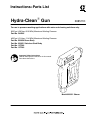
Instructions--Parts List
Hydra-CleanR Gun
308511K
For use in pressure washing applications with water and cleaning solutions only.
5000 psi (280 bar, 28.0 MPa) Maximum Working Pressure
Part No. 24X295
4500 psi (314 bar, 13.4 MPa) Maximum Working Pressure
Part No. 803350 Brass Body
Part No. 803351 Stainless Steel Body
Part No. 15T282
Part No. 15T283
Important Safety Instructions
Read all warnings and instructions in this manual.
Save these instructions.
Model 803351 Shown
Table of Contents
Warnings . . . . . . . . . . . . . . . . . . . . . . . . . . . . . . . . . . . . . . 2
Service . . . . . . . . . . . . . . . . . . . . . . . . . . . . . . . . . . . . . . . 5
Parts . . . . . . . . . . . . . . . . . . . . . . . . . . . . . . . . . . . . . . . . . 6
Technical Data . . . . . . . . . . . . . . . . . . . . . . . . . . . . . . . . . 9
Warranty . . . . . . . . . . . . . . . . . . . . . . . . . . . . . . . . . . . . . 10
Graco Information . . . . . . . . . . . . . . . . . . . . . . . . . . . . . 10
Symbols
Warning Symbol
Caution Symbol
WARNING
CAUTION
This symbol alerts you to the possibility of serious
injury or death if you do not follow the instructions.
This symbol alerts you to the possibility of damage to
or destruction of equipment if you do not follow the
instructions.
WARNING
EQUIPMENT MISUSE HAZARD
Equipment misuse can cause the equipment to rupture or malfunction and result in serious injury.
D This equipment is for professional use only.
D Read all instruction manuals, tags, and labels before operating the equipment.
D Use the equipment only for its intended purpose. If you are not sure, call your Graco distributor.
D Do not alter or modify this equipment.
D Check equipment daily. Repair or replace worn or damaged parts immediately.
D Do not exceed the maximum working pressure stated on the equipment or in the Technical Data
for your equipment. Do not exceed the maximum working pressure of the lowest rated component
in your system.
D Use fluids and solvents which are compatible with the equipment wetted parts. Refer to the Technical Data section of all equipment manuals. Read the fluid and solvent manufacturer’s warnings.
D Handle hoses carefully. Do not pull on hoses to move equipment.
D Route hoses away from traffic areas, sharp edges, moving parts, and hot surfaces. Do not expose
Graco hoses to temperatures above 66_C (150_F) or below --40_C (--40_F).
D Wear hearing protection when operating this equipment.
D Do not move or lift pressurized equipment.
D Comply with all applicable local, state, and national fire, electrical, and safety regulations.
2
308511
WARNING
SKIN INJECTION HAZARD
Spray from the gun/valve, leaks or ruptured components can inject fluid into your body and cause extremely serious injury, including the need for amputation. Fluid splashed in the eyes or on the skin can
also cause serious injury.
D Fluid injected into the skin might look like just a cut, but it is a serious injury. Get immediate
surgical treatment.
D Do not point the gun at anyone or at any part of the body.
D Do not put your hand or fingers over the spray tip/valve nozzle.
D Do not stop or deflect leaks with your hand, body, glove or rag.
D Do not “blow back” fluid; this is not an air spray system.
D Always have the tip guard and the trigger guard on the gun/valve when spraying/dispensing.
D Be sure the gun trigger safety operates before spraying.
D Lock the gun trigger safety when you stop spraying.
D Follow the Pressure Relief Procedure on page 4 if the spray tip clogs and before cleaning,
checking or servicing the equipment.
D Tighten all fluid connections before operating the equipment.
D Check the hoses, tubes, and couplings daily. Replace worn, damaged, or loose parts immediately.
Permanently coupled hoses cannot be repaired; replace the entire hose.
FIRE AND EXPLOSION HAZARD
Improper grounding, poor ventilation, open flames or sparks can cause a hazardous condition and result in a fire or explosion and serious injury.
D If there is any static sparking or you feel an electric shock while using this equipment, stop spraying/dispensing immediately. Do not use the equipment until you identify and correct the problem.
D Provide fresh air ventilation to avoid the buildup of flammable fumes from solvents or the fluid
being sprayed/dispensed.
D Keep the spray/dispense area free of debris, including solvent, rags, and gasoline.
D Before operating this equipment, electrically disconnect all equipment in the spray/dispense area.
D Before operating this equipment, extinguish all open flames or pilot lights in the spray/dispense
area.
D Do not smoke in the spray/dispense area.
D Do not turn on or off any light switch in the spray/dispense area while spraying/dispensing or while
operating if fumes are present.
D Do not operate a gasoline engine in the spray/dispense area.
TOXIC FLUID HAZARD
Hazardous fluid or toxic fumes can cause serious injury or death if splashed in the eyes or on the skin,
inhaled, or swallowed.
D Know the specific hazards of the fluid you are using.
D Store hazardous fluid in an approved container. Dispose of hazardous fluid according to all local,
state and national guidelines.
D Always wear protective eyewear, gloves, clothing and respirator as recommended by the fluid and
solvent manufacturer.
308511
3
Operation
Pressure Relief Procedure
WARNING
SKIN INJECTION HAZARD
The system pressure must be manually
relieved to prevent the system from
starting or spraying accidentally. Fluid
under high pressure can be injected through the
skin and cause serious injury. To reduce the risk of
an injury from injection, splashing fluid, or moving
parts, follow the Pressure Relief Procedure
whenever you:
D
D
D
D
Trigger Safety Latch
Always engage the gun safety latch whenever you
stop cleaning, even for a moment. The latch must be
pulled fully up to make the gun inoperative. Failure to
properly set the safety latch can result in accidental
triggering of the gun. See Fig. 1.
are instructed to relieve the pressure,
stop spraying,
check or service any of the system equipment,
or install or clean the spray tip.
1. Engage the gun trigger safety latch.
2. Turn the gas engine or electric motor off.
TRIGGER SAFETY LATCH SHOWN ENGAGED
3. On a gas engine, remove the ignition cable from
the spark plug. On electric powered equipment,
disconnect the power supply. On air powered
equipment, disconnect the air supply.
4. Shut off the water supply.
5. Disengage the gun trigger safety latch and trigger
the gun to relieve pressure. Then, engage the
safety latch again.
6. If you are not going to use a gasoline powered
pressure washer again before storing it (even
overnight) or transporting it, close the fuel shutoff
valve.
4
308511
04612
TRIGGER SAFETY LATCH SHOWN DISENGAGED
Fig. 1
Service
WARNING
To reduce the risk of serious injury whenever you
are instructed to relieve pressure, always follow the
Pressure Relief Procedure on page 4.
NOTE: The number in parentheses in the text correspond to those on the Parts Drawings on pages 6
through 9.
Valve Replacement
Models 803350, 803351, 15T282, and 15T283
b. Drop the ball (19) into the valve body (on top
of the previously installed seat). Drop the
spring (18) on top of the ball.
c.
Install a new washer (17) on the plug (16).
Screw the plug into the valve body and tighten
securely.
d. Install an o-ring (9) into the valve body and
backup ring (8) on the retaining nut (7).
Grease the o-ring. Grease the outside of the
rod (10) and install through the center of the
retaining nut. The rod must be installed with
the rounded end out toward the trigger.
e. Screw the actuator nut into the valve body and
tighten securely.
1. Remove the screws that hold the left hand sideplate (1) and the right hand sideplate (23) together.
Separate the two sideplates. Remove the assembled parts from the inside of the gun.
7. Reinstall the trigger.
2. Press the trigger pin out of the valve body (14) and
remove the trigger (3).
8. Reassemble the left hand sideplate and right hand
sideplate with the seven screws.
3. Clamp the valve body in a vise.
Valve Body Replacement
4. Unscrew the plug (16), and the retaining nut (7)
from the valve body (14).
5. Remove the washer (17), spring (18), ball (19),
o-ring (21), seat (20), rod (10), backup ring (8),
and o-ring (9) from the valve body.
6. To install the new valve:
a. Install the o-ring (21) on the seat (20). Grease
the o-ring. Push the seat (and o-ring) into the
valve body (14) from the back side. (The seat
must be installed with the chamfered seat
being put into the valve body facing the ball.)
1. Follow steps 1--5 under Valve Replacement.
2. Remove the outlet (4) and inlet (13) from the valve
body (14). Remove the plug (15) from the valve
body.
3. Install the plug (15) into the valve body using pipe
thread sealant on the threads. Tighten the plug
securely.
4. Install an outlet (4) and inlet (13) into the valve
body using pipe thread sealant on the threads.
TIghten both securely.
5. Follow steps 6--8 under Valve Replacement.
308511
5
Parts
Models 803350 and 15T283
4
23
14
15
1
6
7
8
9
17
16
10
11
21 20 19
18
13
22
12
3
Ref.
No.
1
3
4
6
7
8*
9*
10*
11
12
13
14
6
Part No.
Description
803355
803357
803358
803359
803360
SIDEPLATE, left
TRIGGER
TUBE, outlet
STRIKER
NUT, retaining, actuator
RING, backup
O-RING
ROD
PIN
LATCH, trigger
TUBE, inlet
HOUSING
803354
803361
803362
803363
308511
Qty.
1
1
1
1
1
1
1
1
1
1
1
1
Ref.
No.
15
16
17*
18
19*
20*
21*
22
23
*
8042A
Part No.
Description
803364
803365
PLUG
PLUG
WASHER
SPRING
BALL, SST
SEAT
O-RING
SCREW, m3.5 x 18
SIDEPLATE, right
803353
803369
Theses parts are available in Repair Kit 803352.
Qty.
1
1
1
1
1
1
1
7
1
Parts
Models 803351 and 15T282
23
22
15
4
14
21
6
7
8
17
16
9 10
11
1
20
19 18
13
25
3
24
12
8044A
Ref.
No.
1
3
4
5
6
7
8*
9*
10*
12
13
14
15
Part No.
Description
803384
803357
803379
803354
803359
803374
SIDEPLATE, left
TRIGGER
TUBE, outlet
PIN
STRIKER
NUT, retaining, actuator
RING, backup
O-RING
ROD
LATCH, trigger
TUBE, inlet
HOUSING
PLUG
803361
803377
803380
803381
Qty.
1
1
1
1
1
1
1
1
1
1
1
1
1
Ref.
No.
16
17*
18
19*
20*
21*
22
23
24
25
*
Part No.
Description
803382
PLUG
WASHER
SPRING
BALL, SST
SEAT
O-RING
FITTING, outlet
SIDEPLATE, right
SCREW, m3.5 x 18
FITTING, inlet
803353
803372
803369
803378
Qty.
1
1
1
1
1
1
1
1
7
1
Theses parts are available in Repair Kit 803352.
308511
7
Parts
Models 247879 and 17B529
1
2
2
4
3
5
9
6
NOTES:
1
Apply sealant prior to assembly
2
Apply PTFE tape to all threaded parts
1
2
7
1
Ref.
No.
2*
3
4
5
6
Part No.
Description
15R579
15T279
COUPLER, 1/4--18 to 1/4 QD SST
GUN, wand, SST, 32 in.
SLEEVE, safety, 18 in.
HANDLE, wand
GUN, spray
(for Model 247879)
(for Model 17B529)
15T283
24X295
8
308511
Qty.
1
1
1
1
1
Ref.
No.
Part No.
7*
8*
C20483
15R397
9
*
2
8
Description
FITTING, nipple, hex
FITTING, quick release,
SST 3/8--18 NPT
SLEEVE, safety, 9 in.
These parts are available in Stainless Steel
Connection Kit 247880.
1
2
Qty.
1
1
1
Parts
Model 24X295
9147A
Ref.
No.
Part No.
Description
*
24X295
GUN, spray
sold complete
Qty.
1
Technical Data
Models 803350 and
15T283
Model 247879
Models 803351
and 15T282
Model 24X295
17B529
1.7 lb (0.8 kg)
4.35 lb (2.0 kg)
1.9 lb (0.9 kg)
1.2 lb (0.5 kg)
3.85 lb. (1.7 kg)
Dimensions
8.0 x 7.3 x 1.3 in.
(203 x 185 x 33 mm)
42.5 x 9.3 x 2.5 in.
(1080 x 236 x 64
mm)
8.9 x 5.8 x 1.3 in.
(226 x 147 x 33
mm)
8.0 x 7.3 x 1.3 in.
(203 x 185 x 33
mm)
42.5 x 9.3 x 2.5 in.
(1080 x 236 x 64
mm)
Fluid Outlet
1/4 npt
1/4 QD
1/4 npt
1/4 npt
1/4 QD
Fluid Inlet
3/8 npt
3/8 QD
3/8 npt
3/8 npt
3/8 QD
Wetted
Parts
Buna-N, PTFE,
Brass, Stainless
Steel
Buna-N, PTFE,
Brass, Stainless
Steel
Buna-N, PTFE,
Stainless Steel
Buna-N, PTFE,
Brass, Stainless
Steel
Buna-N, PTFE,
Brass, Stainless
Steel
Weight
308511
9
Graco Standard Warranty
Graco warrants all equipment manufactured by Graco and bearing its name to be free from defects in material and workmanship on the
date of sale to the original purchaser for use. With the exception of any special, extended, or limited warranty published by Graco,
Graco will, for a period of twelve months from the date of sale, repair or replace any part of the equipment determined by Graco to be
defective. This warranty applies only when the equipment is installed, operated and maintained in accordance with Graco’s written
recommendations.
This warranty does not cover, and Graco shall not be liable for general wear and tear, or any malfunction, damage or wear caused by
faulty installation, misapplication, abrasion, corrosion, inadequate or improper maintenance, negligence, accident, tampering, or substitution of non--Graco component parts. Nor shall Graco be liable for malfunction, damage or wear caused by the incompatibility of
Graco equipment with structures, accessories, equipment or materials not supplied by Graco, or the improper design, manufacture,
installation, operation or maintenance of structures, accessories, equipment or materials not supplied by Graco.
This warranty is conditioned upon the prepaid return of the equipment claimed to be defective to an authorized Graco distributor for
verification of the claimed defect. If the claimed defect is verified, Graco will repair or replace free of charge any defective parts. The
equipment will be returned to the original purchaser transportation prepaid. If inspection of the equipment does not disclose any defect
in material or workmanship, repairs will be made at a reasonable charge, which charges may include the costs of parts, labor, and
transportation.
THIS WARRANTY IS EXCLUSIVE, AND IS IN LIEU OF ANY OTHER WARRANTIES, EXPRESS OR IMPLIED, INCLUDING BUT
NOT LIMITED TO WARRANTY OF MERCHANTABILITY OR WARRANTY OF FITNESS FOR A PARTICULAR PURPOSE.
Graco’s sole obligation and buyer’s sole remedy for any breach of warranty shall be as set forth above. The buyer agrees that no other
remedy (including, but not limited to, incidental or consequential damages for lost profits, lost sales, injury to person or property, or any
other incidental or consequential loss) shall be available. Any action for breach of warranty must be brought within two (2) years of the
date of sale.
Graco makes no warranty, and disclaims all implied warranties of merchantability and fitness for a particular purpose in connection
with accessories, equipment, materials or components sold but not manufactured by Graco. These items sold, but not manufactured
by Graco (such as electric motors, switches, hose, etc.), are subject to the warranty, if any, of their manufacturer. Graco will provide
purchaser with reasonable assistance in making any claim for breach of these warranties.
In no event will Graco be liable for indirect, incidental, special or consequential damages resulting from Graco supplying equipment
hereunder, or the furnishing, performance, or use of any products or other goods sold hereto, whether due to a breach of contract,
breach of warranty, the negligence of Graco, or otherwise.
FOR GRACO CANADA CUSTOMERS
The parties acknowledge that they have required that the present document, as well as all documents, notices and legal proceedings
entered into, given or instituted pursuant hereto or relating directly or indirectly hereto, be drawn up in English. Les parties reconnaissent avoir convenu que la rédaction du présente document sera en Anglais, ainsi que tous documents, avis et procédures judiciaires
exécutés, donnés ou intentés à la suite de ou en rapport, directement ou indirectement, avec les procedures concernées.
Graco Information
For the latest information about Graco products, visit www.graco.com.
For patent information, see www. graco.com/patents.
TO PLACE AN ORDER, contact your Graco distributor or call to identify the distributor closest to you:
Toll Free: 1--800--690--2894
All written and visual data contained in this document reflects the latest product information available at the time of publication.
Graco reserves the right to make changes at any time without notice.
Original instructions. This manual contains English. MM 308511
Graco Headquarters: Minneapolis
International Offices: Belgium, China, Japan, Korea
GRACO INC. P.O. BOX 1441
10
MINNEAPOLIS, MN
55440--1441
Copyright 1994, Graco Inc. All Graco manufacturing locations are registered to ISO 9001
www.graco.com
Revision K, February 2015
308511