1
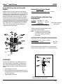
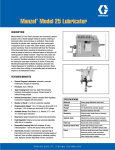
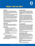
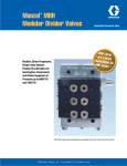
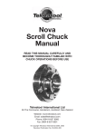
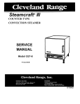
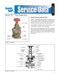
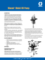
Manzel Model 88 Pump
®
DESCRIPTION
The Model 88 Pump is a heavy-duty precision metering pump
capable of accurately pumping small flows of either mineral or
synthetic oil to machinery injection points. The single-piston
pump is mechanically driven from a camshaft in the reservoir
and is adjustable from 1 to 27 drops per stroke, depending on
the piston size. The pump can develop pressures up to 7500
psi, depending on the piston size. All working parts are totally
enclosed away from dirt, water, and impurities and self-lubricated
at all times by the fluid in the reservoir.
Model 88 Pumps are designed for use in Manzel® Model 55 and
76 Box Lubricators, and in Mega, Lincoln and Premier Model 55
Box Lubricators. The output ranges vary slightly depending on the
lubricator.
Model 88 Pumps are rugged, heavy duty units. Each pump
includes a precision machined steel sleeve fitted with an alloy
steel piston.
The pump is actuated by a hardened steel roller - rocker following
a cam for low wear and longer life. The visual sight well is onepiece injection molded material that is impervious to ultra-violet
rays, and mineral and synthetic oils.
Three (3) piston sizes are available to produce outputs up to 27
drops per stroke in Manzel Box Lubricators and up to 20 drops per
stroke in Mega, Lincoln and Premier Model 55 Box Lubricators.
FEATURES/BENEFITS
•
•
•
•
•
Rugged construction for high performance and durability
Suction and gravity/pressure feed models for application
flexibility
Pump output is easily adjustable
Hardened cam roller adds to pump and cam life
One piece sight glass means fewer leak path and seal
points
OPERATION
Pumps With Vacuum Feed
(Sight Glass Type)
Rotation of the lubricator cam actuates the pump rocker arm
assembly to operate the pump piston. On the piston downstroke,
spring force is exerted on the piston causing it to follow the cam. As
it moves down, a pressure reduction is created in the area between
the piston and the discharge check valve. The supply inlet shutoff
ball is concurrently unseated and lubricant is drawn into the piston
cylinder from the sight well. This action creates a pressure reduction
(vacuum) in the air- tight sight well, causing lubricant from the
reservoir to be drawn into the well until pressure is equalized. On
the piston upstroke, the oil in the piston cylinder reseats the inlet
shutoff ball and is forced out through the discharge check valve to the
machine injection point.
The number of drops seen falling in the sight well equals the amount
of oil discharged by the pump. Pump volume can be adjusted by
means of an external screw. This changes the length of the piston
stroke which changes the pump discharge volume.
L51025
Manzel ® Model 88 Pump
Pumps With Gravity Feed and Pressurized
Supplies
Rotation of the lubricator cam actuates the pump rocker arm
assembly to operate the pump piston. On the piston downstroke,
spring force is exerted on the piston causing it to follow the cam.
As it moves down, a pressure reduction is created in the area
between the piston and the discharge check valve. The gravity
feed or pressurized supply unseats the supply inlet shutoff ball
and fills the piston bore with lubricant. On the piston upstroke, the
oil in the piston cylinder reseats the inlet shutoff ball and is forced
out through the discharge check valve to the machine injection
point. Pump volume can be adjusted by means of an external
screw. This changes the length of the piston stroke which
changes the pump discharge volume.
Calculate Pints Per Day As Follows:
Number of Drops/Min. X 1440 (Minutes in a Day) = Pints/Day
14115 (Number of drops in a Pint)
Calculate Minimum or Maximum Pump
Output Capacity
Input Speed X Pump Output X 1440
Gear Ratio (Min. or Max.
(Min./day)
drops/stroke*)
14115 (Number of Drops in a Pint)
=
Min. or Max. Pump Output
(Pints Per Day)
* Minimum and Maximum Drops Per Stroke Listed in Specifications on the next page.
NOTE: For proper sizing select the appropriate
lubricator brand. Brand as well as piston
size will effect minimum and maximum
pump capacity.
The following example is a Manzel lubricator, electric motor driven,
300:1 internal ratio, 1/4" pump model 88. Solve for maximum flow:
1725 Motor Speed X Max. 12 drops X 1440 Min.
300:1 Gear Ratio
per stroke
14115 (Number of Drops in a Pint)
=
Max. 7.04
Pints/day
To Calculate Minimum: Replace the maximum 12 drops per stroke
with the minimum 2 drops per stroke: (1.17 minimum pints per day)
ADJUSTMENT
Pump discharge (output flow) can be adjusted within the min./
max. ranges as shown in the illustration. The adjustment is
linear. Therefore, positioning the screw midway will produce
one-half of the pump capacity. To adjust the flow, proceed as
follows:
1. Loosen adjusting screw locknut.
2. Turn the adjusting screw to the desired position and, with
the pump operating, count the drops falling in the sight well
for a one-minute interval.
3. Tighten adjusting screw locknut.
*Should not reciprocate up and down as pump operates, on
pumps built beginning in January 1997.
Page 2
L51025
Manzel ® Model 88 Pump
Specifications
Piston Dia
(inches)
Max
Pressure 3
(psi)
Max
Min
Max
Min
Max
Min
Max
Min
In Manzel
Lubricator
(55 and 76)
88B, F, J
3/16
7500
6
1
0.013
0.002
0.213
0.033
50
3
88C, G, K
1/4
6000
12
2
0.024
0.004
0.393
0.066
50
3
88E, H, L
3/8
2500
27
4
0.055
0.004
0.901
0.131
50
3
In Mega,
Lincoln or
Premier
Lubricators
88B, F, J
3/16
7500
5
1
0.009
0.002
0.148
0.033
50
3
88C, G, K
1/4
6000
9
2
0.018
0.004
0.295
0.066
50
3
88E, H, L
3/8
2500
20
4
0.041
0.004
0.672
0.131
50
3
Pump Model 4
1.
2.
3.
4.
5.
Drops/Stroke 1&2
Cu.In./Stroke
Cu.Cm/Stroke
Stroke/Minute
Stroke
Length
(inches)
1/2
3/8
Based on 500 SUS oil at 700F ambient. Heavier oil will produce fewer but larger drops.
When approaching maximum outputs, some oils will stream rather than form drops in sight glass.
For operating pressures over 50% of the rated maximum , consult the factory.
Allowable viscosity range independent of temperature: 80-5000 SUS.
Maximum allowable inlet pressure: Pressurized pump, 100 PSI; Pressurized pump with sight glass, 10 PSI.
NOTE: Any static positive pressure applied to the pump inlet has the potential to cause leakage flow through a pump at rest or adjusted for zero stroke unless offset by a check valve
of comparable pressure rating located at the pump outlet. The "discharge check valve" pictured has no spring and is rated at zero PSI. The "outlet check valve" pictured in
phantom in view at bottom of next page is rated at 35 PSI.
Ordering Information
Vacuum Feed Pump
Gravity Feed Pump & Pressurized Pump5
Gravity Feed Pump w/Sight Glass5
Pump
Piston Size
Model
Part No.
Old Part No.
Model
Part No.
Old Part No.
Model
Part No.
Old Part No.
3/16 in
88B
562954
376-000-001
88F
562962
376-000-121
88J
564011
376-000-530
1/4 in
88C
562956
376-000-011
88G
562964
376-000-131
88K
562967
376-000-540
3/8 in
88E
562958
376-000-031
88H
562966
376-000-151
88L
562968
376-000-560
Model 88 Pumps Configured for Mega, Lincoln and Premier Box Lubricator, and for Manzel Model 55
Lubricator
Model 88 Pumps are interchangeable with Mega, Lincoln and Premier Model 55 Pumps. Use the following table to determine the appropriate part
number.
Ordering Information
Description
Pump Size
Part No.
Old Part No.
Mega Part No.
Premier Part No.
Lincoln Part No.
*Vacuum Pumps (B)
3/16
562954
**376-000-001
–
–
–
*Vacuum Pumps (C)
1/4
562956
**376-000-011
039315
91200/91220
880187/880550
*Vacuum Pumps (E)
3/8
562958
**376-000-031
039308
91201/91221
880330/880560
Press Supply (F)
3/16
562962
376-000-121
–
–
–
Press Supply (G)
1/4
562964
376-000-131
039488
91202
880453/880552
Press Supply (H)
3/8
562966
376-000-151
039489
91203
880454
Press Supply w/Sight Glass (J)
3/16
564011
376-000-530
–
–
–
Press Supply w/Sight Glass (K)
1/4
562967
376-000-540
–
–
–
Press Supply w/Sight Glass (L)
3/8
562968
376-000-560
–
–
–
Press Supply to Front
3/16
562962
†376-000-121
–
–
–
Press Supply to Front
1/4
562964
†376-000-131
038704
91208
880087-X
Press Supply to Front
3/8
562966
† 376-000-151
038705
91209
880402-X
Press Supply to Rear
3/16
562962
†376-000-121
–
–
–
Press Supply to Rear
1/4
562964
†376-000-131
038702
91206
880087-CL
Press Supply to Rear
3/8
562966
† 376-000-151
038703
91207
880402-CL
Press Supply w/Shutoff
3/16
562962
†376-000-121
–
–
–
Press Supply w/Shutoff
1/4
562964
†376-000-131
039425
91204
880087
Press Supply w/Shutoff
3/8
562966
† 376-000-151
038153
91205
880402
*When configured from the factory to fit into Model 55, Mega, Lincoln or Premier Box Lubricators, the vacuum pump has a 0.875 in shortened suction tube.
**Model 88B, C and E pumps can be field modified to fit Mega, Lincoln and Premier Box Lubricators. Remove the strainer, break off the suction tube at the V-groove, and
replace the strainer.
†Graco will provide pump replacement only, customer to supply tubing and fittings for rear, front and shutoff pumps.
Page 3
MANZEL MODEL 88 PUMP OPERATING INSTRUCTIONS
1.
Fill the box lubricator reservoir, to the top of the sight level gauge,
with oil, filtered through a 25 micron nominal strainer. (Machine
requirements may dictate a higher oil cleanliness level.)
2.
Expel all air from the pump. NOTE: Do not connect the oil line to the
pump outlet or lube point until all air has been expelled. To Expel Air
From The Pump:
a.
Remove the sight well plug.
b.
Fill the sight well to the top with filtered oil.
c.
Operate the hand priming assembly until the oil level
drops below the end of the drip tube.
d.
Replace the sight well plug.
e.
Continue to hand prime until oil from the drip tube is free
of air.
9.
Connect the tubing to the pump outlet.
5.
Hand prime the pump until clean, air-free oil is flowing through the
lube line.
6.
Connect the tubing to the lube point.
7.
The lubricator is now ready to operate. After start-up, the lubricator
may require adjustment of the individual pumps to meet required
flow rates.
8.
To adjust The Pump:
Repeat (7-c) to assure that the pump is adjusted to the proper
specification.
f.
Once the pump has been adjusted to the proper specification,
tighten the adjusting screw locknut.
The recommended minimum flow rate is 2 drops per stroke. Operators
are cautioned against decreasing the oil flow below this rate, as a pump
malfunction may occur.
10. The minimum recommended strokes per minute is 3. The maximum
recommended strokes per minute is 50. NOTE: To maximize pump life,
it is recommended that the pump not exceed 20 strokes per minute.
11. Oil level in the sight well will stabilize promptly, then rise and fall slightly
during pump operation. Should oil level in the sight well rise above the
drip tube: f.If all oil is evacuated from sight well, repeat steps (a) through
(e) as often as necessary, until all air has been expelled.
4.
e.
a.
Remove the sight well plug.
b.
Allow the pump to continue to operate until the oil level has
dropped below the drip tube.
c.
Replace the sight well plug. NOTE: This condition is not
uncommon for a vacuum type pump. However it could be an
indication of a problem with the supply inlet shutoff ball/seat.
If this condition persists, check the ball and seat. If there are
no apparent problems there, the piston and bore are worn
and the pump should be replaced.
12. Should oil level in the sight well fall below the pump body surface:
a.
Remove the sight well plug.
a.
Loosen the adjusting screw lock nut.
b.
b.
Turn the adjusting screw clockwise or counterclockwise
to decrease or increase flow.
Allow the pump to continue to operate, and manually fill the
sight well with filtered oil to below the end of the drip tube.
c.
c.
With the lubricator operating, count the drops falling into
the sight well for one minute.
d.
If any further adjustment is necessary, turn the
adjustment screw; 1) counterclockwise to increase flow
(drops per minute); or 2) clockwise to decrease flow
(drops per minute).
Replace the sight well plug. NOTE: This condition could be an
indication of a problem with the seal between the sight glass
and pump body surface, or with the sight well plug. Check
parts for nicks, cuts and sealing capability. Replace parts
using Repair Kit Part No. 564437 (560-001-860) if needed.
PUMP DIMENSIONS
13. The MANZEL MODEL 88 PUMP will operate in a Manzel, Mega, Lincoln,
or Premier lubricator. For more information about the Manzel Force Feed
Box Lubricator, refer to Manzel Bulletin L51020 and/or L51040.
PUMP REPAIR KITS
`
DIMENSION A
B1 B2
C
D
E
F
G1 G2 H1 H2 J
K
INCHES 2.31 4.625 4.406
5.375
0.75 1.50 3.00 8.53 7.75 5.53 4.75 2.625 1.00
MILLIMETERS
58.7
117.5
111.9
136.5
19.1
38.1
76.2
216.7
196.8
140.5
120.6 66.7 25.4
B1/G1/H1 - in Manzel "76" Lubricator; B2/G2/H2 - in Manzel "55"
Mega, Lincoln and Premier Lubricator.
•
Pump repair kits are the same for both vacuum feed and gravity
feed with sight glass pumps in all pump sizes. Repair kits may
be ordered by part number 564437 (560-001-860) and contain
only parts necessary to replace the pump sight glass.
•
Body/sleeve and piston subassembly is not sold separately.
Fluid Measurement Conversion Data
1 Drop
approx 0.002 cu.in.
14,115 Drops
1 pint
28.89 cu.in.
1 pint
490 Drops
1 cu.in.
10 Drops/Min
1 pint/24 hours
30 Drops
1cc
All written and visual data contained in this document are based on the latest product information available at the time of publication. Graco reserves the right to make changes at any time without notice.
Contact us today!
To receive product information or talk with a Graco representative,
call 800-533-9655 or visit us online at www.graco.com.
©2006-2009 Graco Inc. Form No. L51025 Rev. B 4/09 Printed in U.S.A. All other brand names or marks are used for identification purposes and are trademarks of their respective owners. All written and
visual data contained in this document are based on the latest product information available at the time of publication. Graco reserves the right to make changes at any time without notice.