1
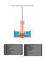
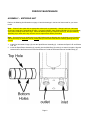
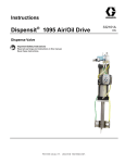
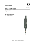
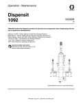
Instructions Dispensit 332090A 1095 Dispense Valve Important Safety Instructions Read all warnings and instructions in this manual. Save these instructions. EN MODEL 1095-10 POSITIVE DISPLACING METERING UNIT OPERATING AND MAINTENANCE MANUAL Table of Contents GENERAL INFORMATION ......................................................................................page 1 DESCRIPTION .......................................................................................................page 1 SAFETY INFORMATION .........................................................................................page 1 DESCRIPTION OF OPERATION .............................................................................page 2 SETUP PROCEDURE ..............................................................................................page 2 MOUNTING ............................................................................................................page 2 DISPENSE HEAD ..................................................................................................page 2 AIR CONTROLLER................................................................................................page 2 OIL ..........................................................................................................................page 2 DRY SYSTEM CHECKOUT .....................................................................................page 3 WET SYSTEM CHECKOUT ....................................................................................page 3 MATERIAL LOADING............................................................................................page 3 Periodic Maintenance .............................................................................................page 4 TROUBLESHOOTING .............................................................................................page 8 Recommended Spare Parts ..................................................................................page 8 WARRANTY AND LIABILITY ..................................................................................page 9 GENERAL INFORMATION DESCRIPTION The Model 1095-10 Positive Displacing Metering Unit provides precise metering and volumetric consistency over a wide range of viscosities, extending from viscous materials to ultrahigh silicones and epoxies with material inlet pressures up to a maximum of 1200 psi. The Model 1095-10 ships complete with the following: • Model 1095-10 Positive Displacing Metering Unit • Operating Manual SAFETY INFORMATION Only properly trained employees with a knowledge of the operations and safety warnings as set forth in this manual should use this product. Read all applicable manuals completely before operating. WARNING: Do not exceed 100 psi (690 kPa) pressure on the operating system. Do not exceed 1200 psi (82.7 bar) material inlet pressure for valves with steel spools. Do not exceed 400 psi (27.6 bar) for valves with plastic spools. Higher pressures may cause damage to equipment and/or personal injury. Note: The recommended pneumatic operating system pressure is 70 psi (clean/dry air). Toxicity and flammability hazards depend upon the product being dispensed by this unit, and the user should take appropriate safety precautions as shown on the MSDS of the product. Always wear safety glasses. page 1 DESCRIPTION OF OPERATION The 1095-10 Positive displacing Metering Unit’s sequencing is as follows. In the normal “ready” state: The material enters the unit through the material inlet port located on the bottom of the body (stamped “IN”) to fill the spool and dispense cavities. The spool shifts to the dispense position, internally blocking the material inlet port and opening the dispense outlet. The dispense cycle begins. The metering rod cycles, pushing material from the dispense cavity through the outlet port (stamped “OUT”) to an ON/OFF dispense valve (not part of the 1095-10). To refill the dispense cavity, the spool shifts again, blocking the material outlet port, opening the material inlet port. At the same time the metering rod rises and the cavity fills. The system is now in the normal “ready” state. SETUP PROCEDURE MOUNTING Mount the 1095-10 base plate perpendicular to a smooth surface using the mounting holes provided. DISPENSE HEAD Connect the 1095-10 to a high pressure ON/OFF dispense head using a flexible hose having a very low volumetric expansion ratio within the specified pressure ranges. Note: We recommend Stainless Steel braided PTFE line. AIR CONTROLLER Operation of the 1095-10 Positive Displacing Metering Unit requires a controller that can provide the following: 3 • A minimum of 0.5 SCFM (2.3 cm ) of dry, unlubricated air at a minimum pressure of 70 psi (483 kPa). • Time delay capability to allow the unit to cycle. page 2 DRY SYSTEM CHECKOUT This is an initial checkout to decide the completion of the system setup. Conduct the dry checkout without material in the system. Attach the pneumatic pressure lines from the supply to the push-in connectors on the end caps. Turn on the electric and air supply. Set the air pressure to 70 psi (48.3 kPa) on the system pressure gauge. Momentarily activate the controllers dispense cycling control switch. The 1095-10 Positive Displacing Metering Unit should go through a complete cycle and cause a slight fluctuation in the system pressure gauge. When this happens, the system installation is correct. WET SYSTEM CHECKOUT MATERIAL LOADING Attach the material line from the reservoir to the material inlet port (stamped "IN") on the bottom of the 1095-10 Positive Displacing Metering Unit. Attach the regulated air line to the 1055-10 Positive Displacing Metering Unit and set the air pressure control to 70 psi. Note: The dispense head, reservoir, delivery tubing, and fittings, must be compatible with the material being dispensed. These must also be capable of withstanding the dispensing pressure. • Make certain that all screws, air connections, and the reservoir connections are tight before applying operating or reservoir air pressure. • Do not exceed 100 psi (690 kPa) pressure on the operating system. • Do not exceed 1,200 psi (8,274 kPa) material pressure. Do not exceed 400 psi (27.6 bar) for valves with plastic spools. Cycle the 1095-10 Positive Displacing Metering Unit several times until a smooth material flow emerges. page 3 PERIODIC MAINTENANCE Refer to the 1095 Metering Unit Illustration on the next page. 1. At the top of the valve, remove the two Screws (1) and remove the Top Cap (2). Remove the Metering Rod (8) if it was not previously removed. 2. Remove the Posipak Seal (7) from the Top Cap (2). Remove the O-ring (21). 3. Remove the four Screws (14) and the End Cap (5) on each side of the valve. 4. Remove the two Spool Shift Pistons (16) from the End Caps (5). They should come out easily but if not use low pressure (less than 2 psi or .1 bar) air at the Push-In Connector (13) to move them. Remove the U-cup seals (17) from the Spool Shift Pistons (16). 5. Remove the Dispense Sleeve (3) from the Main Body (4). If the sleeve is plastic and does not slide out readily then you can thread an appropriately sized tap into it a turn or two and pull it out. A few turns of threads in the plastic will do no harm but wear or cracking will mean that you must replace it. Keep track of which end of the sleeve you tapped into as you will want it at the top again upon reassembly. 6. Remove the Screws (19) that hold the Oil Cup Seal Plates (9) to each side of the Main Body (4). The Seal Retainer Washers (11), and the Posipak Seals (10 and 7) will come off with the Oil Cup Seal Plates. Remove those seals and the O-rings (20). 7. Push the Spool/Sleeve Assembly (6) out with a finger. If it does not slide out, tap it gently using a wood or plastic dowel. A worn spool and sleeve assembly must be replaced with a new (matched) assembly. If you are rebuilding multiple valves be sure to keep the spools and sleeves matched. 8. Remove the O-rings (18) from the Spool/Sleeve Assembly (6). 9. Check the contents of the seal kit versus what you removed then discard the old items. Page 4 MODEL 1095 METERING UNIT ILLUSTRATION 1 SCREW,SHC,#10-32 X 7/8 11 SEAL RETAINER WASHER 2 TOP CAP 12 POSIPAK SEAL 3 DISPENSE SLEEVE 13 PUSH-IN CONNECTOR 4 MAIN BODY 14 SCREW, SHC 10-32 x 2.50 SS 5 END CAP 15 PLUG,SOCKET,1/8 NPT 6 SPOOL/SLEEVE ASSEMBLY 16 SPOOL SHIFT PISTON 7 POSIPAK SEAL 17 U-CUP SEAL 8 METERING ROD 18 O-RING 9 OIL CUP SEAL PLATE 19 SCREW,SHC,#10-32 X 1-1/4 10 POSIPAK SEAL 20 O-RING 21 O-RING Page 5 PERIODIC MAINTENANCE ASSEMBLY – METERING UNIT Refer to the Metering Unit Illustration on page 12 and the drawings in the back of this manual for your exact model. Note: Clean all valve parts with an appropriate solvent prior to reassembly. Always install new, lubricated O-rings and seals when assembling the valve. Use Krytox 203GPL (part number 84/0200-K3/11) for lubricating valve parts including seals and o-rings. Check the Metering Rod (8), Dispense Sleeve (3), and Spool/Sleeve Assembly (6) for wear and if they are worn secure replacements before proceeding. Note: Use caution as you install new U-cup and Posipak seals so that they are not pinched or torn. Do this by making sure they are lubricated, and by tucking the lips of the seal inward before uniformly pushing them into position. 1. Install four lubricated O-rings (18) onto the Spool/Sleeve Assembly (6). Lubricate the Spool O.D. and Sleeve O.D. too. 2. Insert the Spool/Sleeve Assembly (6) carefully into the Main Body (4) rocking it to ease it into place. Align the bottom holes of the Sleeve piece of the Spool/Sleeve (6) with the inlet/outlet holes of the Main Body (4). Page 6 PERIODIC MAINTENANCE ASSEMBLY – METERING UNIT Install the Seal Plate Cups on the Main Body 3. Install a lubricated O-ring (20) on the left side of the Main Body (4) next to the sleeve part of the Spool/Sleeve Assembly (6). 4. Install lubricated Posipak Seals (7 and 10) in the left Seal Plate Cup (9) so that the O-ring side of both Posipaks will be facing the Main Body (4). Be sure to tuck the lip of the Posipak into its cavity to avoid tearing it. 5. Position the left Seal Cup Plate (9) with the oil cup upwards and slide it over the Spool part of the Spool/Sleeve Assembly (6) with the counterbore for the Seal Retainer Washer (11) facing out. Slide the Seal Retainer Washer (11) over the Spool and install two Screws (19). 6. Repeat steps 3, 4 and 5 for the right side Seal Plate Cups. Mount the Valve End Caps to the Seal Plate Cups 7. Install a lubricated U-cup Seal (17) onto the left Spool Shift Piston (16) with lip side out as shown. Lubricate the bore in the End Cap (5). Slide the piston into the left End Cap (5) tucking the lip of the seal into the End Cap carefully. 8. Install the Piston/End Cap onto the left Oil Cup Seal Plate (9) using four Screws (14). Tighten the screws in a cross pattern gradually to prevent binding due to misalignment (like you would tighten lug nuts on a car tire). 9. Push the Spool into the left side until it contacts the piston. 10. Repeat steps 7 and 8 for the right side. Install the Dispense Sleeve, Top Cap and Metering Rod 11. Lubricate the dispense sleeve bore in the Main Body (4). Insert the Dispense Sleeve (3) into the Main Body (4). Check for threads that may be in the inside of the sleeve due to tapping during removal and make sure these are at the top. 12. Install the lubricated O-ring (21) around the Dispense Sleeve (3). 13. Install the lubricated Posipak Seal (12) into the Top Cap (2). Be sure to tuck the lip of the Posipak into its cavity to avoid tearing it. 14. Insert the Metering Rod (8) through the Top Cap (2) and Posipak Seal (12) carefully. 15. Using the projecting Metering Rod (8) as a guide into the Dispense Sleeve (3), position the Top Cap (2) on the Main Body (4). 16. Install the two Screws (1) through the Top Cap (2) and into the Main Body (4). Tighten the screws in a cross pattern gradually to prevent binding due to misalignment (like you would tighten lug nuts on a car tire). Page 7 TROUBLESHOOTING Review the symptoms below for operating difficulties. With each problem there are one or more possible causes to investigate. NOTHING HAPPENS - If absolutely nothing happens when trying to cycle the 1095-10, check the electric and pneumatic power. VALVE CYCLES, NOTHING DISPENSED - First, make sure the ON/OFF Dispense Valve is sequencing properly with the metering unit. Try to purge the dispense head; this should fix most situations. Then, if nothing dispenses, check to see that there is enough air pressure to the reservoir. Perhaps material has “set up” in the reservoir or supply hoses; examine and clear or replace as necessary. Refer to Wet Checkout and Cleanup sections of the appropriate manuals. IRREGULAR VOLUME DISPENSED - Faulty material will cause irregular dispensing. The material must be a smooth (homogeneous) mixture, without any air trapped in it. A second cause could possibly be that the material is not filling the metering rod chamber fully and in time. Check the reservoir pressure as it may be too low for the type of material being dispensed and/or the cycle time may be too fast. Cycle time is a function of (1) adequate air supply pressure, (2) the duration of supply signal, and (3) the stroke speed. To adjust, follow the directions found in the Operation Adjustments section of this manual. SLOW OR SLUGGISH CYCLE - This may be due to inadequate lubrication of the piston walls. Apply a very thin film of a compatible lubricant to the outside diameter surfaces of the pistons and the U-seals and reassemble. This should restore smooth and consistent operation. Another cause may be misalignment between the Metering Rod and the Metering Body. Loosen the two retaining nuts that hold the body to the mounting bracket assembly. Power the metering rod to its full down position and tighten the Retaining Nuts. The unit is now realigned. ON/OFF DISPENSE VALVE DROOLS OR OOZES - This can result from air trapped in the material being dispensed, wear on the valve seat, or a worn seal in the 1095-10 as well as the ON/OFF valve, or the ON/OFF Valve is out of sequence. Check the sequence and then refer to the Dispense Head Manual. MODEL 1095 RECOMMENDED SPARE PARTS Note: These parts are routine supply items or wear parts not covered by warranty for normal wear. Quantity 1 1 1 1 A/R Description SEAL KIT,1095 DISPENSE SLEEVE METERING ROD SPOOL/SLEEVE ASSEMBLY KRYTOX 203GPL ASSEMBLY LUBRICANT Page 8 Part Number see assembly drawing for part number see assembly drawing for part number see assembly drawing for part number see assembly drawing for part number 84/0200-K3/11 Graco warrants all equipment referenced in this document which is manufactured by Graco and bearing its name to be free from defects in material and workmanship on the date of sale to the original purchaser for use. With the exception of any special, extended, or limited warranty published by Graco, Graco will, for a period of twelve months from the date of sale, repair or replace any part of the equipment determined by Graco to be defective. This warranty applies only when the equipment is installed, operated and maintained in accordance with Graco’s written recommendations. This warranty does not cover, and Graco shall not be liable for general wear and tear, or any malfunction, damage or wear caused by faulty installation, misapplication, abrasion, corrosion, inadequate or improper maintenance, negligence, accident, tampering, or substitution of non-Graco component parts. Nor shall Graco be liable for malfunction, damage or wear caused by the incompatibility of Graco equipment with structures, accessories, equipment or materials not supplied by Graco, or the improper design, manufacture, installation, operation or maintenance of structures, accessories, equipment or materials not supplied by Graco. This warranty is conditioned upon the prepaid return of the equipment claimed to be defective to an authorized Graco distributor for verification of the claimed defect. If the claimed defect is verified, Graco will repair or replace free of charge any defective parts. The equipment will be returned to the original purchaser transportation prepaid. If inspection of the equipment does not disclose any defect in material or workmanship, repairs will be made at a reasonable charge, which charges may include the costs of parts, labor, and transportation. . Graco’s sole obligation and buyer’s sole remedy for any breach of warranty shall be as set forth above. The buyer agrees that no other remedy (including, but not limited to, incidental or consequential damages for lost profits, lost sales, injury to person or property, or any other incidental or consequential loss) shall be available. Any action for breach of warranty must be brought within two (2) years of the date of sale. . These items sold, but not manufactured by Graco (such as electric motors, switches, hose, etc.), are subject to the warranty, if any, of their manufacturer. Graco will provide purchaser with reasonable assistance in making any claim for breach of these warranties. In no event will Graco be liable for indirect, incidental, special or consequential damages resulting from Graco supplying equipment hereunder, or the furnishing, performance, or use of any products or other goods sold hereto, whether due to a breach of contract, breach of warranty, the negligence of Graco, or otherwise. The Parties acknowledge that they have required that the present document, as well as all documents, notices and legal proceedings entered into, given or instituted pursuant hereto or relating directly or indirectly hereto, be drawn up in English. Les parties reconnaissent avoir convenu que la rédaction du présente document sera en Anglais, ainsi que tous documents, avis et procédures judiciaires exécutés, donnés ou intentés, à la suite de ou en rapport, directement ou indirectement, avec les procédures concernées. For the latest information about Graco products, visit www.graco.com. 612-623-6921 contact your Graco distributor or call to identify the nearest distributor. 1-800-746-1334 330-966-3006 • Minneapolis Belgium, China, Japan, Korea • www.graco.com •