1
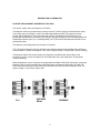
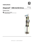
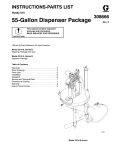
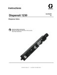
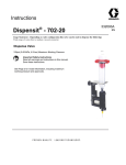
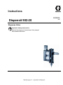
Instructions
332097A
Dispensit 902-20
Dispense Valve
Important Safety Instructions
Read all warnings and instructions in this manual.
Save these instructions.
EN
TABLE OF CONTENTS
GENERAL INFORMATION .................................................................................... page 3
DESCRIPTION ....................................................................................................... page 3
SAFETY INFORMATION ....................................................................................... page 3
DESCRIPTION OF OPERATION ........................................................................... page 4
POSITIVE DISPLACEMENT SEQUENTIAL FUNCTION ...................................... page 4
SET-UP PROCEDURE .......................................................................................... page 5
MOUNTING DISPENSE VALVE ............................................................................ page 5
AIR CONTROLLER ................................................................................................ page 5
DRY SYSTEM CHECKOUT ................................................................................... page 6
MATERIAL LOADING ............................................................................................ page 6
WET SYSTEM CHECKOUT ................................................................................... page 7
CLEANUP ............................................................................................................... page 7
DISPENSING NEEDLE .......................................................................................... page 7
DISPENSE TUBE ................................................................................................... page 7
VALVE DISASSEMBLY .......................................................................................... page 8
CLEANING ............................................................................................................. page 8
VALVE REASSEMBLY ........................................................................................... page 9
TROUBLESHOOTING ......................................................................................... page 10
WARRANTY AND LIABILITY ............................................................................... page 11
2
GENERAL INFORMATION
DESCRIPTION
The Model 902-20 Positive Displacement Pinch Action Dispense Valve with micrometer adjustment is
designed for applications that require dot-to-dot volumetric consistency. It has material viscosity
dispensing capability from water type material to high viscosity epoxies and metal filled pastes. This
valve also has a fail-safe design to prevent material dumping in ease of power failure. All wetted parts
are disposable for easy maintenance and cleaning. It comes complete with the following:
•
Model 902-20 Dispense Valve
•
•
Two 3 foot (1 m) sections of Pneumatic Air Line
One package of Replacement Dispense Tubes (type as ordered)
•
Micrometer-Faceplate Assembly mounted on Dispense Valve
•
Syringe (size as ordered)
•
•
•
Optional Syringe Clamp (comes with syringe option)
Receiver Cap with air line (comes with syringe option)
Operating Manual
SAFETY INFORMATION
This product should be used only by employees who have been given appropriate training and safety
warnings as set forth in this manual. Read completely before operating.
Warning: Do not exceed 100 psi (690 kPa) pressure on the operating system or 60 psi (414 kPa)
pressure on the syringe reservoir. Higher pressures are not required and may cause a serious hazard.
Toxicity and flammability hazards depend upon the product being dispensed by this unit, and the user
should take appropriate safety precautions as indicated on the MSDS of the product.
Always wear safety glasses.
3
DESCRIPTION OF OPERATION
POSITIVE DISPLACEMENT SEQUENTIAL FUNCTION
The normal "ready" state of the system is as follows:
The dispense valve may operate with a (remote) reservoir or with a syringe (mounted with the valve).
In the ready state, the syringe or reservoir contains dispensable material. The system has been
purged, filling the Dispense Tube and needle with material. The Bottom Pinch-Off Piston is not
pressurized (forward) but is held back by the springs, closing the Dispense Tube and holding back the
dispensable material. (See "Fill" on drawing below.) The Top Pinch-Off and Dispense Pistons are not
pressurized (back).
The dispense cycle begins when the controller is activated.
The Top Pinch-Off Piston first moves forward to stop material supply and the Bottom Pinch-Off Piston
moves forward to release the Dispense Tube. (See "Dispense Delay" on Sequential Function drawing.)
The Dispense Piston then moves forward until stopped by the Micrometer Stroke Adjust. This
squeezes a precise amount of material out of the Dispense Tube. (See "Dispense" on Sequential
Function drawing.)
When the dispense cycle is complete, the spring pushes the Bottom Pinch-Off Piston back, sealing the
Dispense Tube to prevent material drip. Immediately after, the Dispense Piston and Top Pinch-Off
Piston withdraw allowing the material from the pressurized reservoir to refill the Dispense Tube. The
system is again, in the normal "ready" state.
FILL
DISPENSE
DELAY
DISPENSE
4
SET-UP PROCEDURE
MOUNTING DISPENSE VALVE
For optimum operation, the Dispense Valve must be mounted on a 1/2 inch (12.7 mm) support rod
post or frame. When mounting, firmly affix the valve in place by tightening the Black Socket Head Cap
Screw with a 5/32 inch Allen Wrench. The valve may be tilted to a maximum of ±60° from the vertical
depending on the application.
AIR CONTROLLER
Operation of the 902-20 Dispense Valve requires a controller that can provide the following:
• A minimum of 0.5 SCFM (2.3 cm3/s) of dry, unlubricated air at a minimum pressure of 70 psi (483
kPa).
• Time delay capability to allow the valve to cycle.
• Independent air pressure regulators for material reservoir and valve operation.
• "Purge capability" which is the ability to pass or not pass air to the Lower Pinch-Off Piston on the
Dispense Valve.
• For semi-automatic or automatic applications, a foot switch or another automatic control to cycle the
valve.
•Connection for .16” ID X .25” OD (6.35mm) pressure tubing for use between the Dispense Valve and
controller. (Note: Two 3 foot (1 m) sections of pneumatic air line are provided.)
5
DRY SYSTEM CHECKOUT
This is an initial checkout to determine if the setup has been properly completed. The dry checkout is
conducted without any material in the system.
Attach the pressure lines from the Dispensing Valve to the air outlets on the air supply controller.
Turn on the electric and air supply.
Set the air pressure to 70 psi (483 kPa) on the system pressure gauge.
In the normal rest position, the spring holds the Lower Pitch-Off Piston back, sealing the Dispense
Tube. (See "Fill" on Sequential Function drawing.)
Momentarily press the Dispense Valve Cycling Control Switch.
The Upper Pinch-Off Piston is pressurized, sealing the Dispense Tube while the Lower Pinch-Off
Piston is pressurized to release the Dispense Tube. (See "Dispense Delay" on Sequential Function
drawing.) The Integral Dispense Piston moves to the Micrometer Stop.
The Dispense Valve air solenoid valve should cycle and show a slight fluctuation in the system
pressure gauge. (See "Dispense" on Sequential Function drawing.)
When this happens, the system is correctly installed.
MATERIAL LOADING
1
Place the filled syringe of material through the syringe clamp, mating the syringe to the Dispense
Tube. Then tighten the syringe clamp using the adjustment knob until snug. Install the Receiver cap
Assembly to the top of the syringe.
1
NOTE: These instructions assume the material is supplied from a valve-mounted syringe, if the
material supply is remote mounted, connect the material supply hose to the valve's luer lock fitting
instead.
6
WARNING: Do not apply either operating or reservoir air pressure to the product unless all screws are
in place and properly tightened, and the receiver cap and/or the reservoir are properly in place and
tightened. All air connections should be fastened securely.
Attach the air line to the regulator and set the air pressure control to 15 psi (103 kPa) or to the setting
required for the application. (Note: When using a remote reservoir, the delivery tubing and fittings must
be compatible with the material being dispensed and capable of withstanding the dispensing pressure.)
WARNING: Do not exceed 100 psi (690 kPa) pressure on the operating system or 60 psi (414 kPa)
pressure on the syringe reservoir. Higher pressures are not required and may cause a serious hazard.
WET SYSTEM CHECKOUT
Using the purge cycle on the air supply controller, run the material through the Dispense Line until a
smooth material flow comes through the Dispensing Needle.
After the purge cycle has been completed, set the air supply controller to the manual cycle mode and
cycle the Dispense Valve several times.
CLEANUP
The model 902-20 PDP Dispense Valve has been engineered for easy cleanup with needle and a
Disposable Dispense Tube.
DISPENSING NEEDLE
Remove the luer lock type dispensing needles by grasping at the base and twisting one-quarter turn
counter-clockwise. Other needles may bc held in place with a nut, which must be fully unscrewed.
Clean with water or solvent depending on the material dispensed. A fine wire, used cautiously, will
help open clogged needles. Replace if damaged or severely clogged.
WARNING: Do not try to disassemble or clean the unit while it is under pressure.
DISPENSE TUBE
Tube life is difficult to predict due to its dependence on the cycles, speed, downtime and material
dispensed.
A reduction in shot volume is a common sign of a worn Dispense Tube. Periodic inspection of the
Dispensing Tube is recommended. Replace if necessary.
To change the Dispense Tube, DO NOT disassemble the valve.
1. Depressurize the syringe or reservoir, and remove or disconnect it.
2. Pressurize the bottom Piston this is the Purge mode and remove pressure from the Top Piston. (It
may be necessary to push back the Top Piston with a small pointed tool.) The Dispense Tube will now
be completely free of compression.
3. Loosen the Upper and Lower Screw Knobs enough to allow the Dispense Tube to pass out the side
of the valve. Note: Different models have different dispense tube configurations. Removal and
replacement of the tube assembly will vary.
4. Replacement: Replace tubes only with same or equivalent tubing -tubing with different I.D. or O.D.
will change the dispense amount; tubing with different wall thickness will leak, dribble, or have
seriously shortened operating life; tubing with inferior mechanical properties will not last. Pay dose
attention to the way the old tube is installed and use this information to get the new one in properly.
• Some tubes may have luer lock fittings or mechanically similar fittings and it may be necessary to
disassemble them (removing the needle) to replace the tube.
7
• Frequently the new tube comes cut at an angle so the tip is tapered; the allows you to pull it through
luer lock or other fittings which hold the ends. After the tubing is pulled through, cut of the excess
smoothly and squarely.
• Others may use the material delivery tube - pull this tube farther through luer the pinched portion can
be cut off. When the tube becomes too short it will be necessary to replace it.
5. Gently tighten the upper and lower screw knobs after the new tube and needle are replaced.
6. Return air controllers to normal operating modes.
7. Reinstall the syringe or reservoir and purge the valve.
One package of replacement dispense tubes is supplied with some models. If this dispensing system
is new and there is no similar device in your shop, it may be necessary to contact Dispensit to verify
what replacement material/part number you need; once you know what you need, write down the part
number and description here. Remember not to change the tube's
wall thickness.
VALVE DISASSEMBLY
Reference numbers are provided to help identify each part of the 902-20. Refer to the drawing at the
back of this manual.
Note: In addition to the seal kit, these are the parts most likely to require replacement: dispense tube
(15), needle, and needle block.
1. Turn off the material inlet pressure to the valve.
2. Turn off the air intake pressure to the valve.
3. Remove the air pressure lines into (8 & 8). Do not remove the fittings themselves.
4. Remove the material inlet line.
5. At this point you can conveniently remove the dispense valve from its mounting.
6. Disconnect the needle, needle block, and dispense tube fittings.
7. Remove the faceplate assembly (14); loosen and remove three caphead screws (22) holding it in
place. There will be three standoffs released by those screws.
There is a spring behind the backplate. In the next step, hold the backplate with a thumb by the lower
(pinch-off) piston, while removing the screws.
8. Loosen and remove two caphead screws (20) holding the backplate (16) in place. The backplate,
the bottom piston (9), and its springs (11), will come loose from the rest of the valve. You may need to
push on the dispense piston (4) slightly to help with the removal.
9. Remove the compression spring (5) from the top piston (6).
10. Remove the top piston/pinch off (6) and dispense piston (4).
11. Separate the dispense piston (4) and the top/pinch off (6) piston
12. It is not necessary to separate the base (1) and its spacer rods (2).
13. Separate back plate (16) from bottom piston (9) and two compression springs (11). You may use a
tool to hold the compression springs in place while you move the pack plate.
CLEANING
1. Remove all O-rings and U-seals
2. Use the correct solvent on all parts of the valve until it is clean.
3. Lubricate the cylinder bores, the valve sleeve bores and seals with a very light coating of the
lubricant that comes in the seal kit.
The Valve is now ready for reassembly.
8
VALVE REASSEMBLY
Note: Use the new parts that are in your seal kit where possible.
Note: Use caution as you install the new U-seals into the sleeve assembly so you don't pinch or tear
them. Do this by making sure they are lubricated, and by tucking the lips of the U-seal inward before
uniformly pushing it down into the valve sleeve.
Lightly lubricate parts to facilitate reassembly.
Note what direction the old seals face, as you remove them; make sure the new seals face in the
proper direction when you install them.
1. Replace the U-seal (10) on the bottom piston (9)
2. Replace the U-seal (also 10) on the top piston (6).
3. Replace the U-seal (7) on the dispense piston (4).
4. Make sure that you have lubricated cylinders and pistons so you can reassemble them.
5. Reassemble the bottom piston (9) and the compression springs (11) with the back plate (16). You
will need a tool to pry the springs down so that they fit under the back plate. Position the springs
properly.
6. Reassemble the dispense piston (4) and the top pinch off piston (6). This is easiest if you tilt the
dispense piston to slide it in place. Use care (and a blunt instrument if needed) to make sure the Useal fits in properly.
7. Return this (4 & 6) assembly into the upper cylinder in the base (1). Add lubrication if needed. Again,
use care (and a blunt instrument if needed) to make sure the U-seal fits in properly. Position the upper
ridge on the piston towards the top (mounting end) of the base.
8. Place the compression spring (5) over the dispense piston (4).
9. Reinstall the bottom piston (9) and backplate (i6) assembly. Add lubrication if needed. Again, use
care (and a blunt instrument if needed) to make sure the U-seal fits in properly. Align the backplate
holes and the top piston pinch-off to make the parts fit properly.
10. Hold the plate in place with a thumb and install the two 3/g-inch caphead screws (20) in the
recessed holes in the backplate to hold it in place. Turn the screws down, but not tight, so that
movement is possible to align the rest of the parts. Holding all the parts in place for the next step can
be a little difficult; here are two ways to approach the task. (1) Position the valve so the backplate is
level, then stand the spacer rods in place on it and lower the faceplate and screws into them. (2) Hold
the faceplate so three fingers hold the screws in place, put the spacers on the screws, then bring the
valve into place on the faceplate.
11. Reinstall the faceplate/micrometer (14) using the remaining three caphead screws, and three
spacer rods (18). Tighten the screws.
12. Complete the job by remounting the valve and installing the dispense tube.
9
TROUBLESHOOTING
If operating difficulties occur, review the symptoms below. With each problem there are one or more
possible causes which should be investigated to resolve the situation.
Nothing HAPPENS - If absolutely nothing happens when trying to cycle the Dispense Valve, check the
electric/pneumatic power. Check the foot-switch or cycle start switch to be sure it is plugged in,
VALVE CYCLES, NOTHING DISPENSED - First, try to purge the unit; this should fix most situations.
If it doesn't, check to see that there is enough pressure to the reservoir. Perhaps the
Reservoir/Tube/Needle path is clogged; examine and clear or replace as necessary. Consider whether
the material could have "set up" in the system (Refer to Wet Checkout and Cleanup sections).
IRREGULAR VOLUME DISPENSED - Irregular dispensing can usually be attributed to faulty material.
The material must be a smooth (homogeneous) mixture, without any air trapped in it. A second cause
could possibly be that the material is not filling the Dispense Tube fully and in time.
Check the reservoir pressure as it may be too low for the type of material being dispensed and/or the
cycle time may be too fast. Cycle time is a function of the air supply controller. To adjust, follow the
directions found in the controller operating manual.
REDUCED VOLUMES DISPENSED - Check to see if Dispense Tube requires replacement or whether
needle is partially clogged (Refer to Cleanup Section). Wrong pinch tube installed (smaller I.D. will
give smaller dispense).
TUBING LIFE VERY SHORT - Incorrect pinch tube (tube wall thickness is too large).
VALVE DRIPS - Pinch tube needs replacing; wrong pinch tube used (wall thickness too small).
SLOW OR SLUGGISH CYCLE TIME - This may be due to inadequate lubrication of the piston walls.
Remove the upper and Lower Pinch-Off Pistons and the Dispense Piston. Apply a very thin film of
compatible light lubricating oil to the outside diameter surfaces of the pistons and the U-seals and
reassemble. This will restore smooth and consistent operation.
10
11
Graco warrants all equipment referenced in this document which is manufactured by Graco and bearing its name to be free from defects in
material and workmanship on the date of sale to the original purchaser for use. With the exception of any special, extended, or limited warranty
published by Graco, Graco will, for a period of twelve months from the date of sale, repair or replace any part of the equipment determined by
Graco to be defective. This warranty applies only when the equipment is installed, operated and maintained in accordance with Graco’s written
recommendations.
This warranty does not cover, and Graco shall not be liable for general wear and tear, or any malfunction, damage or wear caused by faulty
installation, misapplication, abrasion, corrosion, inadequate or improper maintenance, negligence, accident, tampering, or substitution of nonGraco component parts. Nor shall Graco be liable for malfunction, damage or wear caused by the incompatibility of Graco equipment with
structures, accessories, equipment or materials not supplied by Graco, or the improper design, manufacture, installation, operation or
maintenance of structures, accessories, equipment or materials not supplied by Graco.
This warranty is conditioned upon the prepaid return of the equipment claimed to be defective to an authorized Graco distributor for verification of
the claimed defect. If the claimed defect is verified, Graco will repair or replace free of charge any defective parts. The equipment will be returned
to the original purchaser transportation prepaid. If inspection of the equipment does not disclose any defect in material or workmanship, repairs
will be made at a reasonable charge, which charges may include the costs of parts, labor, and transportation.
.
Graco’s sole obligation and buyer’s sole remedy for any breach of warranty shall be as set forth above. The buyer agrees that no other remedy
(including, but not limited to, incidental or consequential damages for lost profits, lost sales, injury to person or property, or any other incidental or
consequential loss) shall be available. Any action for breach of warranty must be brought within two (2) years of the date of sale.
. These items sold, but not manufactured by Graco (such as electric motors, switches, hose, etc.), are subject to
the warranty, if any, of their manufacturer. Graco will provide purchaser with reasonable assistance in making any claim for breach of these
warranties.
In no event will Graco be liable for indirect, incidental, special or consequential damages resulting from Graco supplying equipment hereunder, or
the furnishing, performance, or use of any products or other goods sold hereto, whether due to a breach of contract, breach of warranty, the
negligence of Graco, or otherwise.
The Parties acknowledge that they have required that the present document, as well as all documents, notices and legal proceedings entered
into, given or instituted pursuant hereto or relating directly or indirectly hereto, be drawn up in English. Les parties reconnaissent avoir convenu
que la rédaction du présente document sera en Anglais, ainsi que tous documents, avis et procédures judiciaires exécutés, donnés ou intentés, à
la suite de ou en rapport, directement ou indirectement, avec les procédures concernées.
For the latest information about Graco products, visit www.graco.com.
612-623-6921
contact your Graco distributor or call to identify the nearest distributor.
1-800-746-1334
330-966-3006
•
Minneapolis
Belgium, China, Japan, Korea
•
www.graco.com
•