1
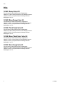
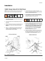
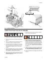
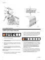
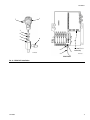
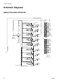
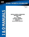
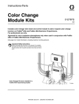
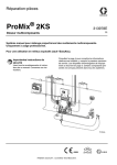
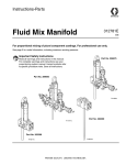
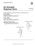
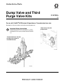
Instructions-Parts
Dump Valve and Third
Purge Valve Kits
312786G
EN
For use with ProMix® 2KS Electronic Proportioners. For professional use only.
See page 2 for kit part numbers and maximum working pressure.
Important Safety Instructions
Read all warnings and instructions in this manual. For complete
warnings and instructions see your proportioning system manual.
Hazard symbols refer to specific procedure risks. Save all instructions.
15V821 Dump Valve Kit
for Wall Panel
15V354 Third Flush Valve Kit
for Wall Panel, shown on
Fluid Mix Manifold
TI12743a
TI12954a
Kits
Kits
15V821 Dump Valve Kit
For wall mount ProMix 2KS Electronic Proportioners
3000 psi (21 MPa, 210 bar) Maximum Fluid Working Pressure
100 psi (0.7 MPa, 7 bar) Maximum Air Working Pressure
See pages 3 and 14
15V822 Robo Dump Valve Kit
For robo mount ProMix 2KS Electronic Proportioners
300 psi (2.1 MPa, 21 bar) Maximum Fluid Working Pressure
100 psi (0.7 MPa, 7 bar) Maximum Air Working Pressure
See pages 6 and 16
15V354 Third Flush Valve Kit
For wall mount ProMix 2KS Electronic Proportioners
4000 psi (28 MPa, 280 bar) Maximum Fluid Working Pressure
100 psi (0.7 MPa, 7 bar) Maximum Air Working Pressure
See pages 5 and 15
15V202 Robo Third Flush Valve Kit
For robo mount ProMix 2KS Electronic Proportioners
300 psi (2.1 MPa, 21 bar) Maximum Fluid Working Pressure
100 psi (0.7 MPa, 7 bar) Maximum Air Working Pressure
See pages 7 and 17
15X247 Auto Dump Valve Kit
For wall mount ProMix 2KS Electronic Proportioners
3000 psi (21 MPa, 210 bar) Maximum Fluid Working Pressure
100 psi (0.7 MPa, 7 bar) Maximum Air Working Pressure
See pages 8 and 18
2
312786G
Installation
Installation
15V821 Dump Valve Kit for Wall Panel
NOTE: These instructions show this kit being installed
on the A side. It may also be installed on the B side.
5. Install the dump valve assembly (includes 1, 2, 4,
and 11) in a slot of the flange (F) at the back of the
wall panel. Secure with the nut (8).
6. Install the elbow (6) in the open port of the dump
valve adapter (2). Connect a 1/4 npsm(f) hose (12)
between the elbow (6) and nipple (19).
1. Shut off the fluid supply to the dose valve (V) at the
front of the wall panel.
2. Actuate the dose valve to relieve fluid pressure in
the valve.
3. Relieve fluid pressure upstream and downstream of
the dose valve. See your ProMix 2KS Operation
Manual.
4. See FIG. 1. Remove the plug from the dose valve
adapter. Install the street elbow (18) in this port.
Install the nipple (19) in the elbow.
7. Shut off all power to the fluid panel. Open the fluid
panel. See the Wall Panel detail in FIG. 2. Install the
solenoid (9) at the correct position (Dump Valve A
or Dump Valve B) on the solenoid manifold. Connect the solenoid wires to the fluid panel control
board as shown in FIG. 3. Also see the System
Electrical Schematic on page 13.
8. Connect the tubing (7) between the solenoid manifold and the tube fitting (T) on the dump valve (1).
See System Pneumatic Schematic, page 10.
At Front of Wall Panel
A SIDE
At Back of Wall Panel
B SIDE
1
12
V
12
T
18
19
TI12744a
6
F
8
2
TI12743a
FIG. 1: 15V821 Kit Installation
312786G
3
Installation
Wall Panel
RoboMix Panel
Dump
Valve B
Dump
Valve A
3rd Flush
Valve
TI12655a
Dump
Valve B
Dump
Valve A
GFB2
3rd Flush
Valve
GFB1
TI13116a
FIG. 2: Solenoid Manifolds
J15-1
J15-2
J15-5
J15-6
J8-1
J8-2 J8-3
J8-4
J8-5
J8-6
3rd Purge Valve
Dump Valve A
Dump Valve B
Auto Dump
Valve A (GFB1)
Auto Dump
Valve B (GFB2)
Wire Color
J15-1
J15-5
J8-5
J8-3
J8-1
Red
J15-2
J15-6
J8-6
J8-4
J8-2
Black
FIG. 3: 255765 Fluid Panel Control Board, Detail View of Solenoid Connections
4
312786G
Installation
15V354 Third Flush Valve Kit for Wall Panel
7. Connect the tubing (13, 14) between the solenoid
manifold and the tube fittings (T) on the flush valve
(2). See System Pneumatic Schematic, page 10.
1. Shut off the air and fluid supply to the ProMix 2KS.
2. Relieve pressure. See your ProMix 2KS Operation
Manual.
3. See FIG. 4. Remove the air flush valve (AFV) from
the fluid mix manifold (FM) and set it aside.
6
1
8
FM
TI12956a
FIG. 5: Install Double Valve Mounting Block
AFV
1
TI12955a
FIG. 4: Disconnect Air Flush Valve
AFV
7
4. See FIG. 5. Install the o-ring (6), double valve
mounting block (1), and screws (8).
2
5. See FIG. 6. Install the air flush valve (AFV) on the
double valve block (1). Assemble the third flush
valve kit parts (2, 3, 4, 6, 9, 10, 11) as shown on
page 15. Install on the mounting block using the
screws (7). See FIG. 6.
TI12957a
FIG. 6: Install Third Flush Valve
6. Shut off all power to the fluid panel. Open the fluid
panel. See the Wall Panel detail in FIG. 2. Install the
solenoid (12) and two tube connectors (15) at the
correct position (3rd Flush Valve) on the solenoid
manifold. Connect the solenoid wires to the fluid
panel control board as shown in FIG. 3.
312786G
5
Installation
15V822 Dump Valve Kit for RoboMix
NOTE: These instructions show this kit being installed
on the B side. It may also be installed on the A side.
1. See FIG. 7. Shut off the fluid supply to the dose
valve (V) in the RoboMix.
2. Actuate the dose valve to relieve fluid pressure in
the valve.
3. Relieve fluid pressure upstream and downstream of
the dose valve. See your ProMix 2KS Operation
Manual.
4. Remove the plug from the dose valve adapter.
Apply thread sealant and install the elbow (8) in this
port.
5. Install the valve adapter (3) in the RoboMix. Secure
with four screws (11). Apply thread sealant and
install the nipple (9) through the back of the RoboMix and into the adapter. Install the swivel (6) in the
opposite side of the adapter.
6. Install the seat (2), o-ring (10), and dump valve (1)
in the adapter (3).
7. Connect the hose (5) between the swivel (6) and
elbow (8).
8. Shut off all power to the fluid panel. Open the fluid
panel. See the RoboMix Panel detail in FIG. 2.
Install the solenoid (4) at the correct position (Dump
Valve A or Dump Valve B) on the solenoid manifold.
Connect the solenoid wires to the fluid panel control
board as shown in FIG. 3. Also see the System
Electrical Schematic on page 13.
9. Connect the tubing (13) between the solenoid manifold and the tube fitting (T) on the dump valve (1).
See System Pneumatic Schematic, page 10.
6
312786G
Installation
1
T
10
2
3
6
TI12655a
Dump
Valve B
5
V
Dump
Valve A
8
4
11
9
TI13047a
TI13045a
FIG. 7: 15V822 Kit Installation
15V202 Third Flush Valve Kit for RoboMix
7. Install the o-ring (2), seat (1), o-ring (6), and third
flush valve (5) in the adapter (3).
1. Shut off the air and fluid supply to the ProMix 2KS.
2. Relieve pressure. See your ProMix 2KS Operation
Manual.
3. See FIG. 8. Remove the plug (A) from the air flush
valve (AFV). Install an o-ring (6) in this port.
4. Install the third flush valve adapter (3) in the RoboMix. Ensure that the o-ring (6) remains in place to
seal between the adapter and the air flush valve
adapter.
5. Secure the adapter (3) to the air flush valve adapter
with four screws (10) inserted through the side wall
of the RoboMix. Torque to 70 in-lb (8 N•m).
6. Apply thread sealant and install the check valve (4)
through the back of the RoboMix and into the third
flush valve adapter (3).
312786G
8. See FIG. 8. Shut off all power to the fluid panel.
Open the fluid panel. Install the solenoid (8) in the
third flush valve position on the solenoid manifold.
Install the tube connector (9). Connect the solenoid
wires to the fluid panel control board as shown in
FIG. 3. Also see the System Electrical Schematic
on page 13.
9. Connect the tubing (13) between the solenoid manifold and the tube fitting (T) on the third flush valve
(5). See System Pneumatic Schematic, page 10.
10. Connect the third flush fluid supply line to the check
valve (4).
7
Installation
9
5
T
6
1
3
6
TI12655a
2
8
4
10
TI13046a
TI13047a
FIG. 8: 15V202 Kit Installation
15X247 Auto Dump Valve Kit
6. Connect a 1/4 npsm(f) dump hose (not supplied) to
the 1/4 npsm(m) threaded stud at the bottom of the
adapter (2). When the gun closes, the dump valve
opens and fluid is dumped through the stud.
1. Close the component A and component B shutoff
valves on the fluid manifold.
2. Trigger the gun to relieve fluid pressure downstream
of the fluid manifold.
3. See FIG. 9. Install the small o-ring (3), seat retainer
(6), large o-ring (7), and dump valve (1) in the valve
adapter (2).
4. Install the valve adapter (2) in the mixed material
line, downstream of the static mixer and as close to
the gun as possible.
NOTE: Connect the static mixer to one 1/4 npt port of
the valve adapter.
5. Install the nipple (8) in the other port of the adapter
(2). Connect the gun line to this nipple.
8
7. Shut off all power to the fluid panel. Open the fluid
panel. See the Wall Panel detail in FIG. 9. Install the
solenoid (5) at the correct position (GFB1 or GFB2)
on the solenoid manifold. Connect the solenoid
wires to J8 on the fluid panel control board as
shown in FIG. 3. Also see the System Electrical
Schematic on page 13.
8. Install the tube connector (9) in the solenoid manifold. Connect the tubing (4) between the connector
and the tube fitting (T) on the dump valve (1). See
System Pneumatic Schematic, page 10.
312786G
Installation
1
T
7
6
3
8
GFB1
GFB2
2
J8 (see FIG. 3
for details)
9
5
TI14283b
4
TI13116a
Wall Panel
FIG. 9: 15X247 Kit Installation
312786G
9
Schematic Diagrams
Schematic Diagrams
System Pneumatic Schematic
COLOR
CHANGE
CONTROL
A B
E
BE
OS
CL 2 TU
/
53 N
E
OP
DOSE A
VALVE
12 VDC
4-WAY SOLENOID
A B
E
BE
OS
CL 2 TU
5/3 N
E
OP
A B
E
BE
OS
CL 2 TU
5/3 N
E
OP
DOSE B
VALVE
12 VDC
05
AIR INPUT
4-WAY SOLENOID
CONTROL AIR
3/8 AIR FILTER
MANUAL DRAIN
5 MICRON
WALL MOUNT ONLY
4-WAY SOLENOID
A B
12 VDC
A B
AIR EXHAUST MUFFLER
PURGE AIR
PURGE A
VALVE
E
BE
OS
CL 2 TU
5/3 N
E
OP
PURGE B
VALVE
E
BE
OS
CL 2 TU
/
53 N
E
OP
PURGE C
VALVE
(OPTIONAL)
E
DUMP A
VALVE
(OPTIONAL)
BE
DUMP B
VALVE
(OPTIONAL)
12 VDC
3-WAY SOLENOID
A
UB
2T
5/3 N
E
OP
A
U
2T
5/3 N
E
P
O
AIR INPUT
12 VDC
3-WAY SOLENOID
3-WAY SOLENOID
E
GFB 1
VALVE
(OPTIONAL)
E
GFB 2
VALVE
(OPTIONAL)
A
UB
2T
5/3 N
E
P
O
A
UB
2T
5/3 N
E
P
O
12 VDC
3-WAY SOLENOID
COLOR 13
COLOR 14
COLOR 15
COLOR 16
COLOR 17
COLOR 18
COLOR 19
COLOR 20
COLOR 21
COLOR 22
COLOR 23
COLOR 24
COLOR 25
COLOR 26
COLOR 27
COLOR 28
COLOR 29
COLOR 30
MAC
36 SERIES SOLENOID VALVES
12 VDC
10
COLOR 1
COLOR 2
COLOR 3
COLOR 4
COLOR 5
COLOR 6
COLOR 7
COLOR 8
COLOR SOLVENT
COLOR 9
COLOR 10
COLOR 11
COLOR 12
CATALYST 1
CATALYST 2
CATALYST 3
CATALYST 4
CATALYST SOLVENT
12 VDC
4-WAY SOLENOID
MANIFOLD
1/4 TUBE
12 VDC
4-WAY SOLENOID
TO MANIFOLD
MANIFOLD
FLUSH AIR TO FLUID INLET
1/4 TUBE
AIR EXHAUST MUFFLER
COLOR
VALVE
STACKS
312786G
Schematic Diagrams
Tubing Schematic
B3
13
B1
13
GFB1-P
A2
GFB2-P
A6
B7
B5
DB
AT
A4
DA
A8
TI13857a
B1
B3
B5
B7
GFB1-C
TI13858a
GFB2-C
GFB1-A
GFB2-A
TI13862a
A2
A4
A6
A8
DA
DB
GFB1-P
GFB1-A
ATOM-1
GFB1
GFB2
GFB1-C
GFB1-S
GFB2-P
GFB2-A
GFB2-C
GFB2-S
TI13863a
312786G
GFB1-S
GFB2-S
ATOM-1
TI13861a
ATOM-2
ATOM-2
TI13860a
11
Schematic Diagrams
Table 1: Tubing Chart
Color
Description
Starting Point
Ending
Point
Tube OD
in. (mm)
Tube Ref. No.
Green
Dose A On
A2
A2
5/32 (4)
336
Green
Dose B On
A4
A4
5/32 (4)
336
Green
Purge A On
A6
A6
5/32 (4)
336
Green
Purge B On
A8
A8
5/32 (4)
336
Green
Dump A
DA
DA
5/32 (4)
Green
Dump B
DB
DB
5/32 (4)
Included in optional
Dump Valve Kit
15V821
Red
Dose A Off
B1
B1
5/32 (4)
337
Red
Dose B Off
B3
B3
5/32 (4)
337
Red
Purge A Off
B5
B5
5/32 (4)
337
Red
Purge B Off
B7
B7
5/32 (4)
337
Natural
Solenoid Air Supply
13
13
1/4 (6)
334
Natural
Gun Flush Box 1 Pressure GFB1-A
Switch Signal
GFB1-A
5/32 (4)
Natural
Gun Flush Box 2 Pressure GFB2-A
Switch Air
GFB2-A
5/32 (4)
Natural
Gun Flush Box 1 Trigger
Air
GFB1-C
GFB1-C
5/32 (4)
Natural
Gun Flush Box 2 Trigger
Air
GFB2-C
GFB2-C
5/32 (4)
Natural
Gun Flush Box 1 Supply
Air
GFB1-P
GFB1-P
5/32 (4)
Natural
Gun Flush Box 2 Supply
Air
GFB2-P
GFB2-P
5/32 (4)
Natural
Gun Flush Box 1 Safety
Interlock
GFB1-S
GFB1-S
5/32 (4)
Natural
Gun Flush Box 2 Safety
Interlock
GFB2-S
GFB2-S
5/32 (4)
Natural
Gun 1 Atomizing Air
ATOM-1
ATOM-1
1/4 (6)
Natural
Gun 2 Atomizing Air
ATOM-2
ATOM-2
1/4 (6)
User supplied. Connects air flow switch to
gun air shutoff valve.
Natural
Purge Air Supply
AT
Use as a separate line
connected directly to the
main shop air line. Do
not connect to the unit’s
main air supply or to the
air manifold (335).
1/4 (6)
338
12
Included in optional
Gun Flush Box Kit
15V826
312786G
Schematic Diagrams
System Electrical Schematic
Hazardous Area
HAZARDOUS AREA
FLUID PANEL CONTROL BOX
FLUID
PANEL
CONTROL
BOARD
J3
J12
J10
1 +12VDC I/S
2 COM
3 SHIELD
J13
J5
MH2
J11
3X CABLE
1
2
3
4
5
6
PWR (RED)
COM (BLACK)
SIG (WHITE)
SHIELD/GRN
PWR (RED)
COM (BLACK)
SIG (WHITE)
SHIELD/GRN
PWR (RED)
COM (BLACK)
SIG (WHITE)
SHIELD/GRN
1
2
3
4
5
6
UNUSED
UNUSED
UNUSED
UNUSED
UNUSED
UNUSED
1
2
3
4
5
6
FLOW METER A
FLOW METER SOLVENT
V/P ANALOG OUT (WHT)
PRESS. (GRN)
+12 V (RED)
GND (BLK)
CHASSIS (BARE)
GROUND
TERMINAL
(10')/
(40')
3
2
5
4
1
6' STD.
(3'-100' OPTIONS)
GRD (BLK)
+12VDC (RED)
SHIELD (BARE)
CAN H (WHT)
CAN L (BLU)
3
2
5
4
1
CLR 8
MANIFOLD
CLR 7
3
2
5
4
1
GRD (BLK)
+12VDC (RED)
SHIELD (BARE)
CAN H (WHT)
CAN L (BLU)
CLR 6
BOOTH
CONTROL
BOARD
CLR 5
CLR 4
CLR 3
J14
J9
312786G
FO OUT
(BLU)
J4
FO IN
(BLK)
J6
J1
BLACK
RED
BLACK
RED
BLACK
RED
BLACK
RED
BLACK
RED
BLACK
RED
6
5
4
3
2
1
6
5
4
3
2
1
BLACK
RED
BLACK
RED
BLACK
RED
BLACK
RED
BLACK
RED
BLACK
RED
1
2
3
4
5
6
7
8
9
10
SIG
COM
SIG
COM
SIG
COM
SIG
COM
SIG
COM
MANIFOLD
CLR 1
DUMP B
GFB #1
GFB #2
DUMP A
MANIFOLD
NOT USED
SOL CLR
1
2
3
4
5
6
+12VDC
COM
+12VDC
COM
+12VDC
COM
1
2
3
4
5
6
+12VDC
COM
+12VDC
COM
+12VDC
COM
1
2
3
4
5
6
J7/J11
PURGE A
NOT USED
NOT USED
DOSE B
DOSE A
AIR FLOW SWITCH 1
AIR FLOW SWITCH 2
1
2
3
4
5
J2
J4
SIG (RED)
COM (BLK)
TECNO
V/P
+ PRESSURE (GRN)
COM (RED)
EX+ (WHT)
- PRESSURE (BLK)
SHIELD (BARE)
FLUID
PRESS.
SENS.
J8
J15
J14
J9
J16
J10
MANIFOLD
6
5
4
3
2
1
COM
+12VDC
COM
+12VDC
COM
+12VDC
6
5
4
3
2
1
COM
+12VDC
COM
+12VDC
COM
+12VDC
CLR 12
6
5
4
3
2
1
COM
+12VDC
COM
+12VDC
COM
+12VDC
CAT 2
CLR 9
CLR 10
CLR 11
CAT 4
CAT 3
CAT 1
SOL CAT
1 4 5 2 3
6' STD.
J7/J11
PURGE C
PURGE B
1
2
1 4 5 2 3
COLOR
BOARD 1
(COLORS
1 THRU 12,
CATALYST
1 THRU 4)
+12VDC
COM
+12VDC
COM
+12VDC
COM
12 VDC
3-WAY SOLENOID
6
5
4
3
2
1
6
5
4
3
2
1
12 VDC
4-WAY SOLENOID
J15
1 FLOW
2 CONTROL
3 BOARD
4
5
J7/J11
CLR 2
J8
J1
1
2
3
4
5
6
50' STD.
J7
I.S. METERS
FLOW METER B
CLR 21
CLR 20
CLR 19
CLR 18
CLR 17
CLR 16
CLR 15
CLR 14
CLR 13
MANIFOLD
1 4 5 2 3
COLOR
BOARD 2
(COLORS
13 THRU 30)
+12VDC
COM
+12VDC
COM
+12VDC
COM
1
2
3
4
5
6
J8
+12VDC
COM
+12VDC
COM
+12VDC
COM
1
2
3
4
5
6
J15
+12VDC
COM
+12VDC
COM
+12VDC
COM
1
2
3
4
5
6
J14
J9
J16
J10
MANIFOLD
6
5
4
3
2
1
COM
+12VDC
COM
+12VDC
COM
+12VDC
6
5
4
3
2
1
COM
+12VDC
COM
+12VDC
COM
+12VDC
CLR 25
6
5
4
3
2
1
COM
+12VDC
COM
+12VDC
COM
+12VDC
CLR 28
CLR 22
CLR 23
CLR 24
CLR 26
CLR 27
CLR 29
CLR 30
SOLVENT FLOW SWITCH
GFB 1 PRESSURE SWITCH
GFB 2 PRESSURE SWITCH
13
Parts
Parts
15V821 Dump Valve Kit for Wall Panel
18
1*
19
*14
*11
*4
*2
15
A B
12
6
13
8
7
TI12742b
Ref.
No.
1*
Part No. Description
Qty
24W310 VALVE, dispense; includes 14; see
1
manual 312782
2*
15T717 ADAPTER, dump valve
1
4*†
111457 O-RING; ptfe
1
6
114342 ELBOW; 1/4 npt (mbe)
1
7
n/a
TUBE; nylon; 5/32 in. (4 mm) OD;
1
2 ft (0.61 m)
8*
n/a
NUT, hex; 9/16-18
1
9
121324 VALVE, solenoid, dump valve
1
11*† n/a
SEAT, dump valve; sst
1
9
TI13116a
Ref.
No.
12
13
Part No. Description
Qty
206966 HOSE; 1-1/2 ft (0.46 m)
1
111328 CONNECTOR; 10-32 x 5/32 in. (4
1
mm) OD tube
14*† n/a
O-RING; ptfe
1
15
101970 PLUG
1
18
166866 ELBOW, street; 1/4 npt (m x f)
1
19
C20482 NIPPLE; 1/4 npt
1
*
Parts included in 16A079 Dump Valve Replacement
Kit (purchase separately).
† Order Kit 16A560 to replace a single seat. The kit
includes a seat (11) and o-rings (4 and 14).
NOTE: The standard valve seat (11) is SST. To install a
carbide seat, order Kit 24U054. The kit includes a single
carbide seat and o-rings 4 and 14.
Parts labeled n/a are not available separately.
14
312786G
Parts
15V354 Third Flush Valve Kit for Wall Panel
6
8
‡11
3
7
5
1
2
‡4
TI12953a
‡6
10
9
12
Ref.
No.
1
2
3
4‡
5
6‡
7
8
9
10
Part No. Description
Qty
15U673 BLOCK, double valve mount
1
15X303 VALVE, dispense; includes item 4;
1
see manual 312782
15T600 ADAPTER, valve
1
n/a
O-RING; ptfe
2
101970 PLUG, pipe; 1/4 npt
3
109450 O-RING; ptfe
5
n/a
SCREW, cap, socket-hd; 5/16-24 x
2
3/4 in. (19 mm)
109031 SCREW, cap, socket-hd; 5/16-24 x
2
1 in. (25 mm)
166866 ELBOW, street; 1/4 npt (m x f)
1
501867 VALVE, check
1
312786G
Ref.
No.
11‡
12
13
14
15
15
TI12652a
Part No.
n/a
121374
n/a
Description
Qty
SEAT, valve
1
VALVE, solenoid, 4-way
1
TUBE; nylon; 5/32 in. (4 mm) OD; 3
1
ft (0.9 m); green
n/a
TUBE; nylon; 5/32 in. (4 mm) OD; 3
1
ft (0.9 m); red
114263 CONNECTOR; 1/8 npt(m) x 5/32 in.
2
(4 mm) OD tube
‡ Parts included in Valve Seat Kit 24A861 (purchase
separately).
Parts labeled n/a are not available separately.
15
Parts
15V822 Dump Valve Kit for RoboMix
1
TI12655a
10
2
Dump
Valve B
3
Dump
Valve A
6
5
4
8
11
TI13047a
9
TI13045a
Ref.
No.
1
2
3
4
5
6
8
9
10
16
Part No. Description
Qty
15X304 VALVE, dispense; includes item 10;
1
see manual 312782
15V888 RETAINER, seat, RoboMix
1
15U713 VALVE, adapter; RoboMix
1
121795 VALVE, solenoid, 4-way
1
15U720 HOSE; 1/4 npt (mbe); 15-1/2 in.
1
(394 mm); ptfe
114339 UNION, swivel; 1/4 npt
1
114446 ELBOW; 1/4 npt(m) x 1/4 npsm(f)
1
166421 NIPPLE; 1/4 npt
1
n/a
O-RING; ptfe
1
Ref.
No.
11
12
13
14
15
16
Part No. Description
Qty
C19979 SCREW, cap, socket-hd; 10-24 x
4
3/8 in. (10 mm)
111328 CONNECTOR; 10-32 x 5/32 in. (4
1
mm) OD tube
n/a
TUBE; nylon; 5/32 in. (4 mm) OD; 3
1
ft (0.9 m); green
114342 ELBOW; 1/4 npt (mbe)
1
104644 PLUG, screw
1
104640 GASKET; buna-N
1
Parts labeled n/a are not available separately.
312786G
Parts
15V202 Third Flush Valve Kit for RoboMix
9
5
6
1
3
2
TI12655a
8
4
10
TI13046a
Ref.
No.
1
2
3
4
5
6
8
9
10
13
TI13047a
Part No.
15V888
109450
15U715
501867
15X304
Description
Qty
RETAINER, seat, RoboMix
1
O-RING; ptfe
1
VALVE, adapter; RoboMix
1
VALVE, check
1
VALVE, dispense; includes item 6;
1
see manual 312782
n/a
O-RING; ptfe
2
121795 VALVE, solenoid, 4-way
1
111328 CONNECTOR; 10-32 x 5/32 in. (4
1
mm) OD tube
110420 SCREW, cap, socket-hd; 10-24 x
4
1-1/2 in. (38 mm)
n/a
TUBE; nylon; 5/32 in. (4 mm) OD; 2
1
ft (0.61 m); green
Parts labeled n/a are not available separately.
312786G
17
Parts
15X247 Auto Dump Valve Kit
1
7
6
3
8
GFB1
GFB2
2
9
5
4
TI14283a
Ref.
No.
1
2
3†
4
5
6†
7†
8
9
Part No.
24W310
15T717
111457
n/a
121324
n/a
n/a
C20482
111328
Description
VALVE, dispense; includes 7 ; see manual 312782
ADAPTER, dump valve
O-RING; ptfe
TUBE; nylon; 5/32 in. (4 mm) OD; 5 ft (1.52 m)
VALVE, solenoid, dump valve
SEAT, dump valve; sst
O-RING; ptfe
NIPPLE; 1/4 npt
CONNECTOR; 10-32 x 5/32 in. (4 mm) OD tube
TI13116a
Qty
1
1
1
1
1
1
1
1
1
† Order Kit 16A560 to replace a single seat. The kit
includes a seat (6) and o-rings (3 and 7).
NOTE: The standard valve seat (6) is SST. To install a
carbide seat, order Kit 24U054. The kit includes a single
carbide seat and o-rings 3 and 7.
Parts labeled n/a are not available separately.
18
312786G
Notes
Notes
312786G
19
Graco Standard Warranty
Graco warrants all equipment referenced in this document which is manufactured by Graco and bearing its name to be free from defects in
material and workmanship on the date of sale to the original purchaser for use. With the exception of any special, extended, or limited warranty
published by Graco, Graco will, for a period of twelve months from the date of sale, repair or replace any part of the equipment determined by
Graco to be defective. This warranty applies only when the equipment is installed, operated and maintained in accordance with Graco’s written
recommendations.
This warranty does not cover, and Graco shall not be liable for general wear and tear, or any malfunction, damage or wear caused by faulty
installation, misapplication, abrasion, corrosion, inadequate or improper maintenance, negligence, accident, tampering, or substitution of
non-Graco component parts. Nor shall Graco be liable for malfunction, damage or wear caused by the incompatibility of Graco equipment with
structures, accessories, equipment or materials not supplied by Graco, or the improper design, manufacture, installation, operation or
maintenance of structures, accessories, equipment or materials not supplied by Graco.
This warranty is conditioned upon the prepaid return of the equipment claimed to be defective to an authorized Graco distributor for verification of
the claimed defect. If the claimed defect is verified, Graco will repair or replace free of charge any defective parts. The equipment will be returned
to the original purchaser transportation prepaid. If inspection of the equipment does not disclose any defect in material or workmanship, repairs
will be made at a reasonable charge, which charges may include the costs of parts, labor, and transportation.
THIS WARRANTY IS EXCLUSIVE, AND IS IN LIEU OF ANY OTHER WARRANTIES, EXPRESS OR IMPLIED, INCLUDING BUT NOT
LIMITED TO WARRANTY OF MERCHANTABILITY OR WARRANTY OF FITNESS FOR A PARTICULAR PURPOSE.
Graco’s sole obligation and buyer’s sole remedy for any breach of warranty shall be as set forth above. The buyer agrees that no other remedy
(including, but not limited to, incidental or consequential damages for lost profits, lost sales, injury to person or property, or any other incidental or
consequential loss) shall be available. Any action for breach of warranty must be brought within two (2) years of the date of sale.
GRACO MAKES NO WARRANTY, AND DISCLAIMS ALL IMPLIED WARRANTIES OF MERCHANTABILITY AND FITNESS FOR A
PARTICULAR PURPOSE, IN CONNECTION WITH ACCESSORIES, EQUIPMENT, MATERIALS OR COMPONENTS SOLD BUT NOT
MANUFACTURED BY GRACO. These items sold, but not manufactured by Graco (such as electric motors, switches, hose, etc.), are subject to
the warranty, if any, of their manufacturer. Graco will provide purchaser with reasonable assistance in making any claim for breach of these
warranties.
In no event will Graco be liable for indirect, incidental, special or consequential damages resulting from Graco supplying equipment hereunder, or
the furnishing, performance, or use of any products or other goods sold hereto, whether due to a breach of contract, breach of warranty, the
negligence of Graco, or otherwise.
FOR GRACO CANADA CUSTOMERS
The Parties acknowledge that they have required that the present document, as well as all documents, notices and legal proceedings entered into,
given or instituted pursuant hereto or relating directly or indirectly hereto, be drawn up in English. Les parties reconnaissent avoir convenu que la
rédaction du présente document sera en Anglais, ainsi que tous documents, avis et procédures judiciaires exécutés, donnés ou intentés, à la suite
de ou en rapport, directement ou indirectement, avec les procédures concernées.
Graco Information
For the latest information about Graco products, visit www.graco.com.
For patent information, see www.graco.com/patents.
TO PLACE AN ORDER, contact your Graco distributor or call to identify the nearest distributor.
Phone: 612-623-6921 or Toll Free: 1-800-328-0211 Fax: 612-378-3505
All written and visual data contained in this document reflects the latest product information available at the time of publication.
Graco reserves the right to make changes at any time without notice.
Original instructions. This manual contains English. MM 312786
Graco Headquarters: Minneapolis
International Offices: Belgium, China, Japan, Korea
GRACO INC. AND SUBSIDIARIES • P.O. BOX 1441 • MINNEAPOLIS, MN 55440-1441 • USA
Copyright 2008, Graco Inc. All Graco manufacturing locations are registered to ISO 9001.
www.graco.com
Revision G, August 2014