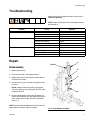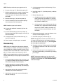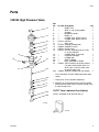
1
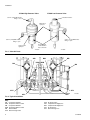
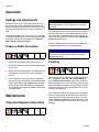
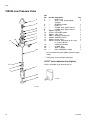
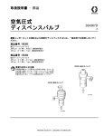
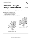
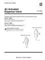
Instructions-Parts
Air Actuated
Dispense Valve
312782D
EN
To dispense plural component fluids and solvents. For professional use only.
Part No. 15X303
High Pressure Dispense Valve
3000 psi (21 MPa, 207 bar) Maximum Fluid Working Pressure
100 psi (0.7 MPa, 7 bar) Maximum Air Working Pressure
Part No. 15X304
Low Pressure Dispense Valve
300 psi (2.1 MPa, 21.0 bar) Maximum Fluid Working Pressure
100 psi (0.7 MPa, 7 bar) Maximum Air Working Pressure
15X304 Low Pressure Valve
Important Safety Instructions
Read all warnings and instructions in this manual. For complete
warnings and instructions see your proportioning system manual.
Hazard symbols refer to specific procedure risks. Save all instructions.
15X303 High Pressure Valve
TI11663A
TI11581A
Related Manuals
Contents
Related Manuals . . . . . . . . . . . . . . . . . . . . . . . . . . . 2
Installation . . . . . . . . . . . . . . . . . . . . . . . . . . . . . . . . 3
Connect the Air Lines . . . . . . . . . . . . . . . . . . . . . 3
Connect the Fluid Lines . . . . . . . . . . . . . . . . . . . 3
Accessories . . . . . . . . . . . . . . . . . . . . . . . . . . . . . 3
Grounding . . . . . . . . . . . . . . . . . . . . . . . . . . . . . . 3
System Pneumatic Schematic (used with
ProMix 2KS) . . . . . . . . . . . . . . . . . . . . . . . . . 5
Operation . . . . . . . . . . . . . . . . . . . . . . . . . . . . . . . . . 6
Settings and Adjustments . . . . . . . . . . . . . . . . . . 6
Pressure Relief Procedure . . . . . . . . . . . . . . . . . 6
Maintenance . . . . . . . . . . . . . . . . . . . . . . . . . . . . . . . 6
Clean the Dispense Valve Daily . . . . . . . . . . . . . 6
Flushing . . . . . . . . . . . . . . . . . . . . . . . . . . . . . . . 6
Troubleshooting . . . . . . . . . . . . . . . . . . . . . . . . . . . 7
Repair . . . . . . . . . . . . . . . . . . . . . . . . . . . . . . . . . . . . 7
Disassembly . . . . . . . . . . . . . . . . . . . . . . . . . . . . 7
Reassembly . . . . . . . . . . . . . . . . . . . . . . . . . . . . 8
Parts . . . . . . . . . . . . . . . . . . . . . . . . . . . . . . . . . . . . . 9
15X303 High Pressure Valve . . . . . . . . . . . . . . . 9
15X304 Low Pressure Valve . . . . . . . . . . . . . . . 10
Technical Data . . . . . . . . . . . . . . . . . . . . . . . . . . . . 11
Graco Standard Warranty . . . . . . . . . . . . . . . . . . . 12
Graco Information . . . . . . . . . . . . . . . . . . . . . . . . 12
2
Related Manuals
See the following manuals for additional information on
the dispense valves.
Manual
Description
312775
312776
312777
312778
312779
312780
ProMix 2KS Manual System Installation
ProMix 2KS Manual System Operation
ProMix 2KS Manual System Repair-Parts
ProMix 2KS Automatic System Installation
ProMix 2KS Automatic System Operation
ProMix 2KS Automatic System
Repair-Parts
Fluid Mix Manifold
Dispense Valve
Color and Catalyst Change Valve Stacks
Color Change Module Kit
312781
312782
312783
312787
312782D
Installation
Installation
FIG. 2 shows the dispense valves installed in an electronic 2-component proportioning system. In this example, the dispense valves are used as dose valves for
components A and B (DVA, DVB), an air purge valve
(APV), and a solvent purge valve (SPV).
FIG. 3 shows a pneumatic schematic of a complete
2-component proportioning system, in which the dispense valves are also used as A and B dump valves,
and color change valves.
Connect the Air Lines
Clean all lines and connections of dirt, burrs, etc., and
blow them out with clean air before connecting them to
the system. The air supply line should contain an air filter to remove harmful dirt and moisture from the compressed air.
Accessories
Two accessories are required in your system: a
bleed-type master air valve and a fluid drain valve.
These accessories help reduce the risk of serious injury
including fluid injection, splashing in the eyes or on the
skin, and injury from moving parts if you are adjusting or
repairing the pump.
The bleed-type master air valve is required only with
air-powered pumps. It relieves air trapped between this
valve and the pump after the air regulator is shut off.
Trapped air can cause the pump to cycle unexpectedly.
Locate the valve close to the pump.
Use a normally closed 4-way air solenoid valve to control the dispense valve. Attach 5/32 in. (4 mm) OD air
supply lines from the 4-way valve to the air inlets of the
dispense valve.
The fluid drain valve helps relieve fluid pressure in the
displacement pump, hose, and dispense valve; triggering the valve to relieve pressure may not be sufficient.
Connect the Fluid Lines
Grounding
Connect a grounded fluid line from the pump or meter to
the 1/4 npt fluid inlet of the dispense valve adapter.
If fluid is supplied by a pump, install a fluid pressure regulator upstream of the dispense valve. A fluid regulator
enables you to control fluid pressure more accurately
than by regulating air pressure to the pump.
Install a fluid filter to remove particles and sediment
which may clog the nozzle.
To reduce the risk of static sparking, ground the pump
and all other components used or located in the dispensing area. Check your local electrical code for
detailed instructions for your area and type of equipment
and be sure to ground all of these components.
•
•
312782D
Fluid hoses: use only electrically conductive hoses
with a maximum of 500 feet (150 m) combined hose
length to ensure grounding continuity.
Dispense valve: obtain grounding through connection to a properly grounded fluid hose and pump.
3
Installation
15X304 Low Pressure Valve
15X303 High Pressure Valve
Actuation indicator
5/32 in. (4 mm) OD air tube
fitting, to close
Optional air
open port
5/32 in. (4 mm) OD air tube
fitting, to open
5/32 in. (4 mm) OD air tube
fitting, to open
Seal weep port
and Lubrication
Cup connection
Valve position
sight port
TI11663A
TI11581A
FIG. 1. Valve Air Ports
ASL
BSL
DVA
MA
MB
DVB
MS
SPV
APV
APL
SPL
TI12556a
FIG. 2: Typical Installation
Key:
MA
DVA
MB
DVB
MS
SPV
4
Component A Meter
Component A Dose Valve
Component B Meter
Component B Dose Valve
Solvent Meter
Solvent Purge Valve
APV
ASL
BSL
APL
SPL
Air Purge Valve
Component A Supply Line
Component B Supply Line
Air Purge Line
Solvent Purge Line
312782D
Installation
System Pneumatic Schematic (used with ProMix 2KS)
COLOR
CHANGE
CONTROL
A B
E
E
OS
CL 2 TUB
5/3 N
E
OP
DOSE A
VALVE
12 VDC
4-WAY SOLENOID
A B
E
E
OS
CL 2 TUB
5/3 N
E
OP
DOSE B
VALVE
12 VDC
05
4-WAY SOLENOID
3/8 AIR FILTER
MANUAL DRAIN
5 MICRON
WALL MOUNT ONLY
A B
E
E
OS
CL 2 TUB
5/3 N
E
OP
PURGE A
VALVE
COLOR 1
COLOR 2
COLOR 3
COLOR 4
COLOR 5
COLOR 6
COLOR 7
COLOR 8
COLOR SOLVENT
COLOR 9
COLOR 10
COLOR 11
COLOR 12
CATALYST 1
CATALYST 2
CATALYST 3
CATALYST 4
CATALYST SOLVENT
12 VDC
4-WAY SOLENOID
A B
E
E
OS
CL 2 TUB
5/3 N
E
OP
PURGE B
VALVE
A B
E
E
OS
CL 2 TUB
5/3 N
E
OP
PURGE C
VALVE
(OPTIONAL)
12 VDC
CONTROL AIR
4-WAY SOLENOID
PURGE AIR
1/4 TUBE
12 VDC
4-WAY SOLENOID
TO MANIFOLD
MANIFOLD
FLUSH AIR TO FLUID INLET
1/4 TUBE
AIR EXHAUST MUFFLER
COLOR
VALVE
STACKS
AIR EXHAUST MUFFLER
12 VDC
3-WAY SOLENOID
E
DUMP A
VALVE
(OPTIONAL)
E
DUMP B
VALVE
(OPTIONAL)
A
UB
2T
5/3 N
E
P
O
A
UB
2T
5/3 N
E
OP
12 VDC
3-WAY SOLENOID
MAC
36 SERIES SOLENOID VALVES
12 VDC
3-WAY SOLENOID
E
GFB 1
VALVE
(OPTIONAL)
E
GFB 2
VALVE
(OPTIONAL)
A
UB
2T
5/3 N
E
P
O
A
UB
2T
5/3 N
E
OP
12 VDC
3-WAY SOLENOID
MANIFOLD
COLOR 13
COLOR 14
COLOR 15
COLOR 16
COLOR 17
COLOR 18
COLOR 19
COLOR 20
COLOR 21
COLOR 22
COLOR 23
COLOR 24
COLOR 25
COLOR 26
COLOR 27
COLOR 28
COLOR 29
COLOR 30
FIG. 3. System Pneumatic Schematic
312782D
5
Operation
Operation
Settings and Adjustments
Set the actuating air to at least 75 psi (0.52 MPa, 5.2
bar) and start the pump. Adjust the pump speed and
pressure to obtain the desired flow rate. Always use the
lowest pump speed necessary to get the results you
want.
To decrease needle travel, turn the cap (11, see pages
9 and 10) clockwise; to increase, turn counterclockwise.
The valve is factory set at one open turn. The maximum setting is four turns open.
Pressure Relief Procedure
NOTICE
Be sure the solvent used is compatible with the fluid
being dispensed, to avoid clogging the valve’s fluid
passages.
An important part of the care and maintenance of your
automatic dispense valve is proper flushing. Flush the
valve daily with a compatible solvent until all traces of
fluid are removed from the valve passages. Relieve the
pressure before flushing.
Clean the outside surfaces of the valve by wiping with a
soft cloth dampened with a compatible solvent.
NOTICE
Never immerse the entire dispense valve in solvent.
Immersing in solvent removes lubricants and may
damage the o-rings.
1. Shut off the fluid supply to the dispense valve.
Flushing
2. Actuate the dispense valve to relieve fluid pressure
in the valve.
3. Relieve fluid pressure upstream and downstream of
the dispense valve. See your system operation
manual.
4. If you suspect the spray tip or hose is clogged or
that pressure has not been fully relieved after following the steps above, very slowly loosen tip guard
retaining nut or hose end coupling to relieve pressure gradually, then loosen completely. Clear hose
or tip obstruction.
Maintenance
Clean the Dispense Valve Daily
6
Before flushing, be sure the entire system and flushing
pails are properly grounded. Refer to Grounding on
page 3. Relieve the pressure. Always use the lowest
possible fluid pressure, and maintain firm metal-to-metal
contact between the dispense valve and the pail during
flushing to reduce the risk of fluid injection injury, static
sparking, and splashing.
Start the pump and flush the system with a compatible
solvent as explained in the instructions for your pump.
Check the system under pressure for leaks; if any are
found, relieve the pressure and repair the leaks. Pressurize the system again and make sure the leaking has
stopped.
312782D
Troubleshooting
Troubleshooting
Before servicing this equipment always make sure to
relieve the pressure.
NOTE: Check all possible causes and solutions before
disassembling.
Problem
Valve will not close.
Valve will not open.
Valve will not dispense.
Cause
Solution
Fluid needle binding.
Clean, repair.
Piston o-rings binding.
Repair.
Obstructed or worn needle or seat.
Clean or replace.
Fluid needle binding.
Clean or repair.
Piston o-rings binding.
Repair.
No trigger or actuator pressure.
Check, clean all lines.
Worn or dry piston o-rings.
Replace.
Fluid supply source is not operating.
Check on fluid supply source.
Fluid line clogged.
Clear.
Fluid valve closed.
Open.
Clogged orifice or needle seat.
Clean.
Repair
C
ON Port
Disassembly
B
1. Relieve the pressure.
2. Flush the valve with a compatible solvent.
A
3. Relieve the pressure after flushing and disconnect
the fluid and air hoses.
4. Unscrew the cap (C) to remove spring pressure on
the valve.
NOTE: Another method of removing spring pressure is by applying air to the ON port, to lift the valve
needle off the seat.
S
5. Unscrew the dispense valve from the adapter (A).
Inspect the needle ball (B). Also inspect the seat (S)
in the adapter for damage. The seat is reversible.
See FIG. 4.
NOTE: See Fluid Mix Manifold Manual 312781 for seat
replacement instructions and part numbers.
312782D
TI12822A
FIG. 4. Valve Adapter and Seat
7
Repair
NOTE: See the parts drawings on pages 9 and 10.
5. On high pressure valves, install the o-ring (17*) on
the air body (6).
6. Unscrew valve cap (11). Remove the spring (12).
7. Hold the needle flats with a wrench to keep it from
turning. Unscrew the piston (9, high pressure
valves) or retainer (10, low pressure valves) from
the needle.
8. Remove the o-rings (7, 8) from the piston (9).
9. Push the needle (22) from the top while pulling it
from the bottom of the fluid body (3).
NOTE: Needle may be hard to remove.
10. Unscrew the needle ball assembly (23) from the
needle (22).
11. Unscrew the fluid body (3) from the air body (6).
Remove the packing (19), bearing (5), and u-cup (4)
from the fluid body.
12. On high pressure valves, remove the o-ring (17)
from the air body (6).
13. Clean, inspect, and replace parts as needed.
Reassembly
NOTE: Seal Kits 15U933 (for high pressure dispense
valve 15X303) and 15W621 (for low pressure dispense
valve 15X304) are available to replace the seals. Parts
included in the kit are marked with an asterisk, for example (4*). For best results, use all the parts in the kit.
NOTE: Use the 262028 Seal Installation Tool (supplied
with the ProMix 2KS) to ensure proper installation of the
u-cup (4).
1. Using the 262028 Installation Tool, install the u-cup
(4*) into the fluid body (3) with the lips facing down.
Install the bearing (5*) and packing (19*).
6. Install the o-rings (7*, 8*) on the piston (9). Lubricate
the o-rings.
7. Reinstall the piston (9):
a. On high pressure valves, apply thread sealant
to the top threads of the needle (22*). Holding
the needle (22) steady by its flats, screw the piston (9) onto the needle (22*).
b. On low pressure valves, slide the piston (9) onto
the needle (22*). Apply thread sealant to the top
threads of the needle. Holding the needle (22)
steady by its flats, screw the retainer (10) onto
the needle.
8. Before performing step 9, screw the dispense valve
securely into the adapter (A, FIG. 4).
9. Install the spring (12) and valve cap (11).
NOTE: On high pressure valves, screw the valve cap
(11) onto the air body (6) only until slight resistance is
felt as the cap contacts the o-ring (17*). Do not tighten
the valve cap (11) at this time.
10. Screw the valve cap (11) down onto the air body (6)
until additional resistance is felt and the cap is tight
with the body.
11. Unscrew the valve cap (11) one complete turn for
the factory needle setting, or unscrew cap to setting
prior to repair.
NOTE: To decrease needle travel, turn the cap (11)
clockwise; to increase, turn counterclockwise. The valve
is factory set at one open turn. The maximum setting
is four turns open.
2. Slide the needle (22*) into the fluid body (3) from
the top, down through the packing (19), bearing (5),
and u-cup (4).
3. Apply thread sealant and screw the needle ball
assembly (23*) onto the needle (22*).
4. Apply thread sealant and screw the fluid body (3)
onto the air body (6).
8
312782D
Parts
Parts
15X303 High Pressure Valve
15
11
12
8*
9
7*
6
13
15
14
*17
Ref.
No.
3
4*
5*
6
7*
8*
9
11
12
13
14
15
17*
19
20*
22*
23*
24
22*
25‡
*
19*
5*
Part No. Description
Qty
--BODY, fluid
1
--SEAL, u-cup, spring applied;
1
uhmwpe
--BEARING, needle
1
--BODY, air
1
--O-RING, shaft, piston; buna-N
1
--O-RING, body, piston; buna-N
1
15T413 PISTON
1
--CAP, valve
1
15T454 SPRING, compression
1
104640 GASKET; buna-N
2
104644 PLUG, screw
2
109193 ELBOW, tube fitting; 10-32 x 5/32
2
in. (4 mm) OD tube
--O-RING, body, air; buna-N
1
--PACKING; uhmwpe
1
--O-RING; ptfe
1
--SHAFT, needle
1
--BALL ASSEMBLY, needle
1
1
15V818 VENT, breather; not shown; remove
(15) and install breather vent in (11)
when valve is used as dump valve
or color change valve
17B969 SPRING, compression (not shown)
1
Parts included in Seal Kit 15U933 (purchase separately).
--- These parts are not available separately.
4*
3
‡ Remove (12) and replace with this spring (marked
with black stain) when valve is used as a dump valve
or color change valve.
23*
15V737 Valve Lubricator Cup (Option)
20*
Install in fluid body (3) to lubricate seal (4).
TI11582A
TI13019A
312782D
9
Parts
15X304 Low Pressure Valve
11
12
10
8*
9
7*
13
6
14
Ref.
No.
3
4*
5*
6
7*
8*
9
10
11
12
13
14
15
15
22*
19*
20*
22*
23*
*
Part No. Description
--BODY, fluid
--SEAL, u-cup, spring applied;
uhmwpe
--BEARING, needle
--BODY, air
--O-RING, shaft, piston; buna-N
--O-RING, body, piston; buna-N
180538 PISTON
15T452 RETAINER, piston
180612 CAP, valve
108017 SPRING, compression
104640 GASKET; buna-N
104644 PLUG, screw
109193 ELBOW, tube fitting; 10-32 x 5/32
in. (4 mm) OD tube
--PACKING; uhmwpe
--O-RING; ptfe
--SHAFT, needle
--BALL ASSEMBLY, needle
Qty
1
1
1
1
1
1
1
1
1
1
2
2
1
1
1
1
1
Parts included in Seal Kit 15W621 (purchase separately).
--- These parts are not available separately.
15V737 Valve Lubricator Cup (Option)
Install in fluid body (3) to lubricate seal (4).
*19
3
*5
*4
23*
20*
TI13019A
TI11664A
10
312782D
Technical Data
Technical Data
Air Specifications
Maximum Air Input Pressure . . . . . . . . . . . . . . . . . . .
Minimum Air Pressure . . . . . . . . . . . . . . . . . . . . . . . .
Air Inlet Fitting Size . . . . . . . . . . . . . . . . . . . . . . . . . .
Fluid Specifications
Maximum Fluid Working Pressure . . . . . . . . . . . . . . .
100 psi (0.7 MPa, 7 bar)
75 psi (0.52 MPa, 5.2 bar)
5/32 in. (4 mm) OD tube
Model 15X303: 3000 psi (21 MPa, 207 bar)
Model 15X304: 300 psi (2.1 MPa, 21 bar)
Wetted Parts . . . . . . . . . . . . . . . . . . . . . . . . . . . . . . . 303 SST, 17-4PH SST, Tungsten Carbide (with nickel
binder), UHMWPE
Weight . . . . . . . . . . . . . . . . . . . . . . . . . . . . . . . . . . . . . . . Model 15X303: 0.5 lb (0.23 kg)
Model 15X304: 0.3 lb (0.14 kg)
312782D
11
Graco Standard Warranty
Graco warrants all equipment referenced in this document which is manufactured by Graco and bearing its name to be free from defects in
material and workmanship on the date of sale to the original purchaser for use. With the exception of any special, extended, or limited warranty
published by Graco, Graco will, for a period of twelve months from the date of sale, repair or replace any part of the equipment determined by
Graco to be defective. This warranty applies only when the equipment is installed, operated and maintained in accordance with Graco’s written
recommendations.
This warranty does not cover, and Graco shall not be liable for general wear and tear, or any malfunction, damage or wear caused by faulty
installation, misapplication, abrasion, corrosion, inadequate or improper maintenance, negligence, accident, tampering, or substitution of
non-Graco component parts. Nor shall Graco be liable for malfunction, damage or wear caused by the incompatibility of Graco equipment with
structures, accessories, equipment or materials not supplied by Graco, or the improper design, manufacture, installation, operation or
maintenance of structures, accessories, equipment or materials not supplied by Graco.
This warranty is conditioned upon the prepaid return of the equipment claimed to be defective to an authorized Graco distributor for verification of
the claimed defect. If the claimed defect is verified, Graco will repair or replace free of charge any defective parts. The equipment will be returned
to the original purchaser transportation prepaid. If inspection of the equipment does not disclose any defect in material or workmanship, repairs
will be made at a reasonable charge, which charges may include the costs of parts, labor, and transportation.
THIS WARRANTY IS EXCLUSIVE, AND IS IN LIEU OF ANY OTHER WARRANTIES, EXPRESS OR IMPLIED, INCLUDING BUT NOT
LIMITED TO WARRANTY OF MERCHANTABILITY OR WARRANTY OF FITNESS FOR A PARTICULAR PURPOSE.
Graco’s sole obligation and buyer’s sole remedy for any breach of warranty shall be as set forth above. The buyer agrees that no other remedy
(including, but not limited to, incidental or consequential damages for lost profits, lost sales, injury to person or property, or any other incidental or
consequential loss) shall be available. Any action for breach of warranty must be brought within two (2) years of the date of sale.
GRACO MAKES NO WARRANTY, AND DISCLAIMS ALL IMPLIED WARRANTIES OF MERCHANTABILITY AND FITNESS FOR A
PARTICULAR PURPOSE, IN CONNECTION WITH ACCESSORIES, EQUIPMENT, MATERIALS OR COMPONENTS SOLD BUT NOT
MANUFACTURED BY GRACO. These items sold, but not manufactured by Graco (such as electric motors, switches, hose, etc.), are subject to
the warranty, if any, of their manufacturer. Graco will provide purchaser with reasonable assistance in making any claim for breach of these
warranties.
In no event will Graco be liable for indirect, incidental, special or consequential damages resulting from Graco supplying equipment hereunder, or
the furnishing, performance, or use of any products or other goods sold hereto, whether due to a breach of contract, breach of warranty, the
negligence of Graco, or otherwise.
FOR GRACO CANADA CUSTOMERS
The Parties acknowledge that they have required that the present document, as well as all documents, notices and legal proceedings entered into,
given or instituted pursuant hereto or relating directly or indirectly hereto, be drawn up in English. Les parties reconnaissent avoir convenu que la
rédaction du présente document sera en Anglais, ainsi que tous documents, avis et procédures judiciaires exécutés, donnés ou intentés, à la suite
de ou en rapport, directement ou indirectement, avec les procédures concernées.
Graco Information
For the latest information about Graco products, visit www.graco.com.
For patent information, see www.graco.com/patents.
TO PLACE AN ORDER, contact your Graco distributor or call to identify the nearest distributor.
Phone: 612-623-6921 or Toll Free: 1-800-328-0211 Fax: 612-378-3505
All written and visual data contained in this document reflects the latest product information available at the time of publication.
Graco reserves the right to make changes at any time without notice.
Original instructions. This manual contains English. MM 312782
Graco Headquarters: Minneapolis
International Offices: Belgium, China, Japan, Korea
GRACO INC. AND SUBSIDIARIES • P.O. BOX 1441 • MINNEAPOLIS MN 55440-1441 • USA
Copyright 2008, Graco Inc. All Graco manufacturing locations are registered to ISO 9001.
www.graco.com
Revision D, August 2014